- Capacitor
-
This article is about the electronic component. For the physical phenomenon, see capacitance. For an overview of various kinds of capacitors, see types of capacitor.
Capacitor 
Modern capacitors, by a cm rulerType Passive Invented Ewald Georg von Kleist (October 1745) Electronic symbol 
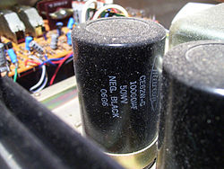
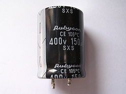 A typical electrolytic capacitor
A capacitor (formerly known as condenser) is a passive two-terminal electrical component used to store energy in an electric field. The forms of practical capacitors vary widely, but all contain at least two electrical conductors separated by a dielectric (insulator); for example, one common construction consists of metal foils separated by a thin layer of insulating film. Capacitors are widely used as parts of electrical circuits in many common electrical devices.
When there is a potential difference (voltage) across the conductors, a static electric field develops across the dielectric, causing positive charge to collect on one plate and negative charge on the other plate. Energy is stored in the electrostatic field. An ideal capacitor is characterized by a single constant value, capacitance, measured in farads. This is the ratio of the electric charge on each conductor to the potential difference between them.
The capacitance is greatest when there is a narrow separation between large areas of conductor, hence capacitor conductors are often called "plates," referring to an early means of construction. In practice, the dielectric between the plates passes a small amount of leakage current and also has an electric field strength limit, resulting in a breakdown voltage, while the conductors and leads introduce an undesired inductance and resistance.
Capacitors are widely used in electronic circuits for blocking direct current while allowing alternating current to pass, in filter networks, for smoothing the output of power supplies, in the resonant circuits that tune radios to particular frequencies and for many other purposes.
Contents
History
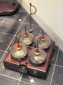
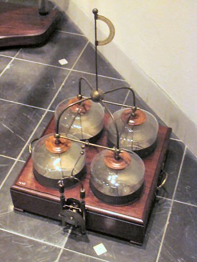
In October 1745, Ewald Georg von Kleist of Pomerania in Germany found that charge could be stored by connecting a high-voltage electrostatic generator by a wire to a volume of water in a hand-held glass jar.[1] Von Kleist's hand and the water acted as conductors, and the jar as a dielectric (although details of the mechanism were incorrectly identified at the time). Von Kleist found, after removing the generator, that touching the wire resulted in a painful spark. In a letter describing the experiment, he said "I would not take a second shock for the kingdom of France."[2] The following year, the Dutch physicist Pieter van Musschenbroek invented a similar capacitor, which was named the Leyden jar, after the University of Leiden where he worked.[3]
Daniel Gralath was the first to combine several jars in parallel into a "battery" to increase the charge storage capacity. Benjamin Franklin investigated the Leyden jar and "proved" that the charge was stored on the glass, not in the water as others had assumed. He also adopted the term "battery",[4][5] (denoting the increasing of power with a row of similar units as in a battery of cannon), subsequently applied to clusters of electrochemical cells.[6] Leyden jars were later made by coating the inside and outside of jars with metal foil, leaving a space at the mouth to prevent arcing between the foils.[citation needed] The earliest unit of capacitance was the 'jar', equivalent to about 1 nanofarad.[citation needed]
Leyden jars or more powerful devices employing flat glass plates alternating with foil conductors were used exclusively up until about 1900, when the invention of wireless (radio) created a demand for standard capacitors, and the steady move to higher frequencies required capacitors with lower inductance. A more compact construction began to be used of a flexible dielectric sheet such as oiled paper sandwiched between sheets of metal foil, rolled or folded into a small package.
Early capacitors were also known as condensers, a term that is still occasionally used today. The term was first used for this purpose by Alessandro Volta in 1782, with reference to the device's ability to store a higher density of electric charge than a normal isolated conductor.[7]
Theory of operation
Main article: Capacitance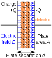 Charge separation in a parallel-plate capacitor causes an internal electric field. A dielectric (orange) reduces the field and increases the capacitance.
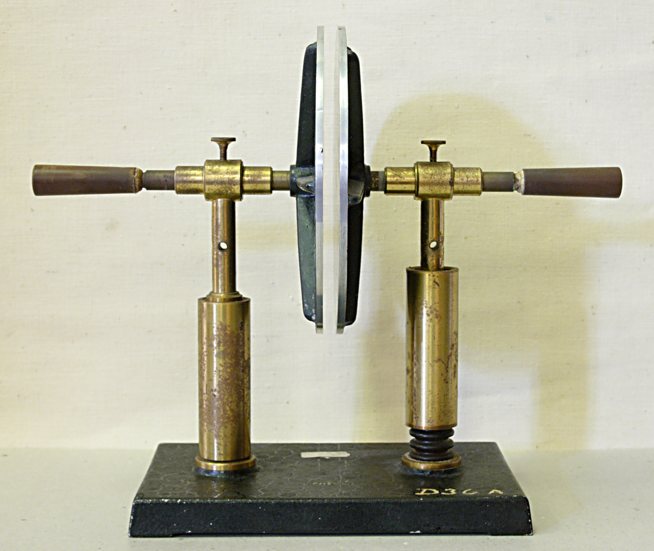
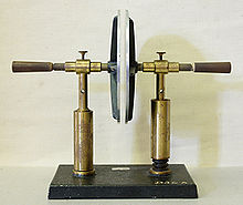 A simple demonstration of a parallel-plate capacitor
A capacitor consists of two conductors separated by a non-conductive region.[8] The non-conductive region is called the dielectric. In simpler terms, the dielectric is just an electrical insulator. Examples of dielectric mediums are glass, air, paper, vacuum, and even a semiconductor depletion region chemically identical to the conductors. A capacitor is assumed to be self-contained and isolated, with no net electric charge and no influence from any external electric field. The conductors thus hold equal and opposite charges on their facing surfaces,[9] and the dielectric develops an electric field. In SI units, a capacitance of one farad means that one coulomb of charge on each conductor causes a voltage of one volt across the device.[10]
The capacitor is a reasonably general model for electric fields within electric circuits. An ideal capacitor is wholly characterized by a constant capacitance C, defined as the ratio of charge ±Q on each conductor to the voltage V between them:[8]
Sometimes charge build-up affects the capacitor mechanically, causing its capacitance to vary. In this case, capacitance is defined in terms of incremental changes:
Energy storage
Work must be done by an external influence to "move" charge between the conductors in a capacitor. When the external influence is removed the charge separation persists in the electric field and energy is stored to be released when the charge is allowed to return to its equilibrium position. The work done in establishing the electric field, and hence the amount of energy stored, is given by:[11]
Current-voltage relation
The current i(t) through any component in an electric circuit is defined as the rate of flow of a charge q(t) passing through it, but actual charges, electrons, cannot pass through the dielectric layer of a capacitor, rather an electron accumulates on the negative plate for each one that leaves the positive plate, resulting in an electron depletion and consequent positive charge on one electrode that is equal and opposite to the accumulated negative charge on the other. Thus the charge on the electrodes is equal to the integral of the current as well as proportional to the voltage as discussed above. As with any antiderivative, a constant of integration is added to represent the initial voltage v (t0). This is the integral form of the capacitor equation,[12]
 .
.
Taking the derivative of this, and multiplying by C, yields the derivative form,[13]
 .
.
The dual of the capacitor is the inductor, which stores energy in the magnetic field rather than the electric field. Its current-voltage relation is obtained by exchanging current and voltage in the capacitor equations and replacing C with the inductance L.
DC circuits
See also: RC circuit A simple resistor-capacitor circuit demonstrates charging of a capacitor.
A series circuit containing only a resistor, a capacitor, a switch and a constant DC source of voltage V0 is known as a charging circuit.[14] If the capacitor is initially uncharged while the switch is open, and the switch is closed at t = 0, it follows from Kirchhoff's voltage law that
Taking the derivative and multiplying by C, gives a first-order differential equation,
At t = 0, the voltage across the capacitor is zero and the voltage across the resistor is V0. The initial current is then i (0) =V0 /R. With this assumption, the differential equation yields
where τ0 = RC is the time constant of the system.
As the capacitor reaches equilibrium with the source voltage, the voltage across the resistor and the current through the entire circuit decay exponentially. The case of discharging a charged capacitor likewise demonstrates exponential decay, but with the initial capacitor voltage replacing V0 and the final voltage being zero.
AC circuits
Impedance, the vector sum of reactance and resistance, describes the phase difference and the ratio of amplitudes between sinusoidally varying voltage and sinusoidally varying current at a given frequency. Fourier analysis allows any signal to be constructed from a spectrum of frequencies, whence the circuit's reaction to the various frequencies may be found. The reactance and impedance of a capacitor are respectively
where j is the imaginary unit and ω is the angular frequency of the sinusoidal signal. The - j phase indicates that the AC voltage V = Z I lags the AC current by 90°: the positive current phase corresponds to increasing voltage as the capacitor charges; zero current corresponds to instantaneous constant voltage, etc.
Impedance decreases with increasing capacitance and increasing frequency. This implies that a higher-frequency signal or a larger capacitor results in a lower voltage amplitude per current amplitude—an AC "short circuit" or AC coupling. Conversely, for very low frequencies, the reactance will be high, so that a capacitor is nearly an open circuit in AC analysis—those frequencies have been "filtered out".
Capacitors are different from resistors and inductors in that the impedance is inversely proportional to the defining characteristic, i.e. capacitance.
Parallel plate model
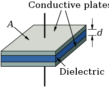 Dielectric is placed between two conducting plates, each of area A and with a separation of d.
The simplest capacitor consists of two parallel conductive plates separated by a dielectric with permittivity ε (such as air). The model may also be used to make qualitative predictions for other device geometries. The plates are considered to extend uniformly over an area A and a charge density ±ρ = ±Q/A exists on their surface. Assuming that the width of the plates is much greater than their separation d, the electric field near the centre of the device will be uniform with the magnitude E = ρ/ε. The voltage is defined as the line integral of the electric field between the plates
Solving this for C = Q/V reveals that capacitance increases with area and decreases with separation
 .
.
The capacitance is therefore greatest in devices made from materials with a high permittivity, large plate area, and small distance between plates. However solving for maximum energy storage using Ud as the dielectric strength per distance and capacitor voltage at the capacitor's breakdown voltage limit V = Vbd = Udd.
we see that the maximum energy is a function of dielectric volume, permittivity, and dielectric strength per distance. So increasing the plate area while decreasing the separation between the plates while maintaining the same volume has no change on the amount of energy the capacitor can store. Care must be taken when increasing the plate separation so that the above assumption of the distance between plates being much smaller than the area of the plates is still valid for these equations to be accurate.
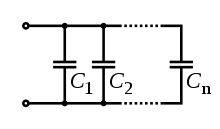 Several capacitors in parallel.
Networks
See also: Series and parallel circuits- For capacitors in parallel
- Capacitors in a parallel configuration each have the same applied voltage. Their capacitances add up. Charge is apportioned among them by size. Using the schematic diagram to visualize parallel plates, it is apparent that each capacitor contributes to the total surface area.
- For capacitors in series
 Several capacitors in series.
- Connected in series, the schematic diagram reveals that the separation distance, not the plate area, adds up. The capacitors each store instantaneous charge build-up equal to that of every other capacitor in the series. The total voltage difference from end to end is apportioned to each capacitor according to the inverse of its capacitance. The entire series acts as a capacitor smaller than any of its components.

- Capacitors are combined in series to achieve a higher working voltage, for example for smoothing a high voltage power supply. The voltage ratings, which are based on plate separation, add up, if capacitance and leakage currents for each capacitor are identical. In such an application, on occasion series strings are connected in parallel, forming a matrix. The goal is to maximize the energy storage of the network without overloading any capacitor.
- Series connection is also sometimes used to adapt polarized electrolytic capacitors for bipolar AC use. Two polarized electrolytic capacitors are connected back to back to form a bipolar capacitor with half the capacitance. The anode film can only withstand a small reverse voltage however. [15] This arrangement can lead to premature failure as the anode film is broken down during the reverse-conduction phase and partially rebuilt during the forward phase.[16] A non-polarized electrolytic capacitor has both plates anodized so that it can withstand rated voltage in both directions; such capacitors have about half the capacitance per unit volume of polarized capacitors.
Non-ideal behaviour
Capacitors deviate from the ideal capacitor equation in a number of ways. Some of these, such as leakage current and parasitic effects are linear, or can be assumed to be linear, and can be dealt with by adding virtual components to the equivalent circuit of the capacitor. The usual methods of network analysis can then be applied. In other cases, such as with breakdown voltage, the effect is non-linear and normal (i.e., linear) network analysis cannot be used, the effect must be dealt with separately. There is yet another group, which may be linear but invalidate the assumption in the analysis that capacitance is a constant. Such an example is temperature dependence. Finally, combined parasitic effects such as inherent inductance, resistance, or dielectric losses can exhibit non-uniform behavior at variable frequencies of operation.
Breakdown voltage
Main article: Breakdown voltageAbove a particular electric field, known as the dielectric strength Eds, the dielectric in a capacitor becomes conductive. The voltage at which this occurs is called the breakdown voltage of the device, and is given by the product of the dielectric strength and the separation between the conductors,[17]
- Vbd = Edsd
The maximum energy that can be stored safely in a capacitor is limited by the breakdown voltage. Due to the scaling of capacitance and breakdown voltage with dielectric thickness, all capacitors made with a particular dielectric have approximately equal maximum energy density, to the extent that the dielectric dominates their volume.[18]
For air dielectric capacitors the breakdown field strength is of the order 2 to 5 MV/m; for mica the breakdown is 100 to 300 MV/m, for oil 15 to 25 MV/m, and can be much less when other materials are used for the dielectric.[19] The dielectric is used in very thin layers and so absolute breakdown voltage of capacitors is limited. Typical ratings for capacitors used for general electronics applications range from a few volts to 1kV. As the voltage increases, the dielectric must be thicker, making high-voltage capacitors larger per capacitance than those rated for lower voltages. The breakdown voltage is critically affected by factors such as the geometry of the capacitor conductive parts; sharp edges or points increase the electric field strength at that point and can lead to a local breakdown. Once this starts to happen, the breakdown quickly tracks through the dielectric until it reaches the opposite plate, leaving carbon behind causing a short circuit.[20]
The usual breakdown route is that the field strength becomes large enough to pull electrons in the dielectric from their atoms thus causing conduction. Other scenarios are possible, such as impurities in the dielectric, and, if the dielectric is of a crystalline nature, imperfections in the crystal structure can result in an avalanche breakdown as seen in semi-conductor devices. Breakdown voltage is also affected by pressure, humidity and temperature.[21]
Equivalent circuit
 Two different circuit models of a real capacitor
An ideal capacitor only stores and releases electrical energy, without dissipating any. In reality, all capacitors have imperfections within the capacitor's material that create resistance. This is specified as the equivalent series resistance or ESR of a component. This adds a real component to the impedance:
As frequency approaches infinity, the capacitive impedance (or reactance) approaches zero and the ESR becomes significant. As the reactance becomes negligible, power dissipation approaches PRMS = VRMS² /RESR.
Similarly to ESR, the capacitor's leads add equivalent series inductance or ESL to the component. This is usually significant only at relatively high frequencies. As inductive reactance is positive and increases with frequency, above a certain frequency capacitance will be canceled by inductance. High-frequency engineering involves accounting for the inductance of all connections and components.
If the conductors are separated by a material with a small conductivity rather than a perfect dielectric, then a small leakage current flows directly between them. The capacitor therefore has a finite parallel resistance,[10] and slowly discharges over time (time may vary greatly depending on the capacitor material and quality).
Ripple current
Ripple current is the AC component of an applied source (often a switched-mode power supply) (whose frequency may be constant or varying). Some types of capacitors, primarily tantalum and aluminium electrolytic capacitors, usually have a rating for maximum ripple current. Ripple current causes heat to be generated within the capacitor due to the current flow across the slightly resistive plates in the capacitor. The equivalent series resistance (ESR) is the amount of external series resistance one would add to a perfect capacitor to model this. ESR does not exactly equal the actual resistance of the plates.
- Tantalum electrolytic capacitors are limited by ripple current and generally have the highest ESR ratings in the capacitor family. Exceeding their ripple limits tends to result in explosive failure.
- Aluminium electrolytic capacitors, the most common type of electrolytic, suffer a large shortening of life expectancy if rated ripple current is exceeded.
- Ceramic capacitors generally have no ripple current limitation and have some of the lowest ESR ratings.
Capacitance instability
The capacitance of certain capacitors decreases as the component ages. In ceramic capacitors, this is caused by degradation of the dielectric. The type of dielectric, ambient operating and storage temperatures are the most significant aging factors, while the operating voltage has a smaller effect. The aging process may be reversed by heating the component above the Curie point. Aging is fastest near the beginning of life of the component, and the device stabilizes over time.[22] Electrolytic capacitors age as the electrolyte evaporates. In contrast with ceramic capacitors, this occurs towards the end of life of the component.
Temperature dependence of capacitance is usually expressed in parts per million (ppm) per °C. It can usually be taken as a broadly linear function but can be noticeably non-linear at the temperature extremes. The temperature coefficient can be either positive or negative, sometimes even amongst different samples of the same type. In other words, the spread in the range of temperature coefficients can encompass zero. See the data sheet in the leakage current section above for an example.
Capacitors, especially ceramic capacitors, and older designs such as paper capacitors, can absorb sound waves resulting in a microphonic effect. Vibration moves the plates, causing the capacitance to vary, in turn inducing AC current. Some dielectrics also generate piezoelectricity. The resulting interference is especially problematic in audio applications, potentially causing feedback or unintended recording. In the reverse microphonic effect, the varying electric field between the capacitor plates exerts a physical force, moving them as a speaker. This can generate audible sound, but drains energy and stresses the dielectric and the electrolyte, if any.
Current and voltage reversal
Current reversal occurs when the flow of current changes direction. Voltage reversal is the change of polarity in a circuit. Reversal is generally described as the percentage of the maximum rated voltage that reverses polarity. In DC circuits this will usually be less than 100%, (often in the range of 0 to 90%), whereas AC circuits experience 100% reversal.
In DC circuits and pulsed circuits, current and voltage reversal are affected by the damping of the system. Voltage reversal is encountered in RLC circuits that are under-damped. The current and voltage reverse direction, forming a harmonic oscillator between the inductance and capacitance. The current and voltage will tend to oscillate and may reverse direction several times, with each peak being lower than the previous, until the system reaches an equalibrium. This is often referred to as ringing. In comparison, critically damped or over-damped systems usually do not experience a voltage reversal. Reversal is also encountered in AC circuits, where the peak current will be equal in each direction.
For maximum life, capacitors usually need to be able to handle the maximum amount of reversal that a system will experience. An AC circuit will experience 100% voltage reversal, while under-damped DC circuits will experience less than 100%. Reversal creates excess electric fields in the dielectric, causes excess heating of both the dielectric and the conductors, and can dramatically shorten the life-expectancy of the capacitor. Reversal ratings will often affect the design considerations for the capacitor, from the choice of dielectric materials and voltage ratings to the types of internal connections used.[23]
Capacitor types
Main article: Types of capacitorPractical capacitors are available commercially in many different forms. The type of internal dielectric, the structure of the plates and the device packaging all strongly affect the characteristics of the capacitor, and its applications.
Values available range from very low (picofarad range; while arbitrarily low values are in principle possible, stray (parasitic) capacitance in any circuit is the limiting factor) to about 5 kF supercapacitors.
Above approximately 1 microfarad electrolytic capacitors are usually used because of their small size and low cost compared with other technologies, unless their relatively poor stability, life and polarised nature make them unsuitable. Very high capacity supercapacitors use a porous carbon-based electrode material.
Dielectric materials
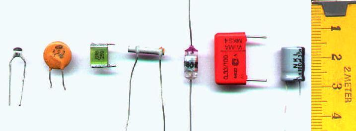
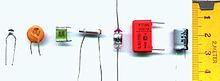 Capacitor materials. From left: multilayer ceramic, ceramic disc, multilayer polyester film, tubular ceramic, polystyrene, metalized polyester film, aluminum electrolytic. Major scale divisions are in centimetres.
Most types of capacitor include a dielectric spacer, which increases their capacitance. These dielectrics are most often insulators. However, low capacitance devices are available with a vacuum between their plates, which allows extremely high voltage operation and low losses. Variable capacitors with their plates open to the atmosphere were commonly used in radio tuning circuits. Later designs use polymer foil dielectric between the moving and stationary plates, with no significant air space between them.
In order to maximise the charge that a capacitor can hold, the dielectric material needs to have as high a permittivity as possible, while also having as high a breakdown voltage as possible.
Several solid dielectrics are available, including paper, plastic, glass, mica and ceramic materials. Paper was used extensively in older devices and offers relatively high voltage performance. However, it is susceptible to water absorption, and has been largely replaced by plastic film capacitors. Plastics offer better stability and aging performance, which makes them useful in timer circuits, although they may be limited to low operating temperatures and frequencies. Ceramic capacitors are generally small, cheap and useful for high frequency applications, although their capacitance varies strongly with voltage and they age poorly. They are broadly categorized as class 1 dielectrics, which have predictable variation of capacitance with temperature or class 2 dielectrics, which can operate at higher voltage. Glass and mica capacitors are extremely reliable, stable and tolerant to high temperatures and voltages, but are too expensive for most mainstream applications. Electrolytic capacitors and supercapacitors are used to store small and larger amounts of energy, respectively, ceramic capacitors are often used in resonators, and parasitic capacitance occurs in circuits wherever the simple conductor-insulator-conductor structure is formed unintentionally by the configuration of the circuit layout.
Electrolytic capacitors use an aluminum or tantalum plate with an oxide dielectric layer. The second electrode is a liquid electrolyte, connected to the circuit by another foil plate. Electrolytic capacitors offer very high capacitance but suffer from poor tolerances, high instability, gradual loss of capacitance especially when subjected to heat, and high leakage current. Poor quality capacitors may leak electrolyte, which is harmful to printed circuit boards. The conductivity of the electrolyte drops at low temperatures, which increases equivalent series resistance. While widely used for power-supply conditioning, poor high-frequency characteristics make them unsuitable for many applications. Electrolytic capacitors will self-degrade if unused for a period (around a year), and when full power is applied may short circuit, permanently damaging the capacitor and usually blowing a fuse or causing arcing in rectifier tubes. They can be restored before use (and damage) by gradually applying the operating voltage, often done on antique vacuum tube equipment over a period of 30 minutes by using a variable transformer to supply AC power. Unfortunately, the use of this technique may be less satisfactory for some solid state equipment, which may be damaged by operation below its normal power range, requiring that the power supply first be isolated from the consuming circuits. Such remedies may not be applicable to modern high-frequency power supplies as these produce full output voltage even with reduced input.
Tantalum capacitors offer better frequency and temperature characteristics than aluminum, but higher dielectric absorption and leakage.[24] OS-CON (or OC-CON) capacitors are a polymerized organic semiconductor solid-electrolyte type that offer longer life at higher cost than standard electrolytic capacitors.
Several other types of capacitor are available for specialist applications. Supercapacitors store large amounts of energy. Supercapacitors made from carbon aerogel, carbon nanotubes, or highly porous electrode materials, offer extremely high capacitance (up to 5 kF as of 2010[update]) and can be used in some applications instead of rechargeable batteries. Alternating current capacitors are specifically designed to work on line (mains) voltage AC power circuits. They are commonly used in electric motor circuits and are often designed to handle large currents, so they tend to be physically large. They are usually ruggedly packaged, often in metal cases that can be easily grounded/earthed. They also are designed with direct current breakdown voltages of at least five times the maximum AC voltage.
Structure
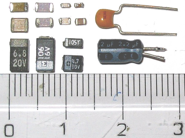
 Capacitor packages: SMD ceramic at top left; SMD tantalum at bottom left; through-hole tantalum at top right; through-hole electrolytic at bottom right. Major scale divisions are cm.
The arrangement of plates and dielectric has many variations depending on the desired ratings of the capacitor. For small values of capacitance (microfarads and less), ceramic disks use metallic coatings, with wire leads bonded to the coating. Larger values can be made by multiple stacks of plates and disks. Larger value capacitors usually use a metal foil or metal film layer deposited on the surface of a dielectric film to make the plates, and a dielectric film of impregnated paper or plastic – these are rolled up to save space. To reduce the series resistance and inductance for long plates, the plates and dielectric are staggered so that connection is made at the common edge of the rolled-up plates, not at the ends of the foil or metalized film strips that comprise the plates.
The assembly is encased to prevent moisture entering the dielectric – early radio equipment used a cardboard tube sealed with wax. Modern paper or film dielectric capacitors are dipped in a hard thermoplastic. Large capacitors for high-voltage use may have the roll form compressed to fit into a rectangular metal case, with bolted terminals and bushings for connections. The dielectric in larger capacitors is often impregnated with a liquid to improve its properties.
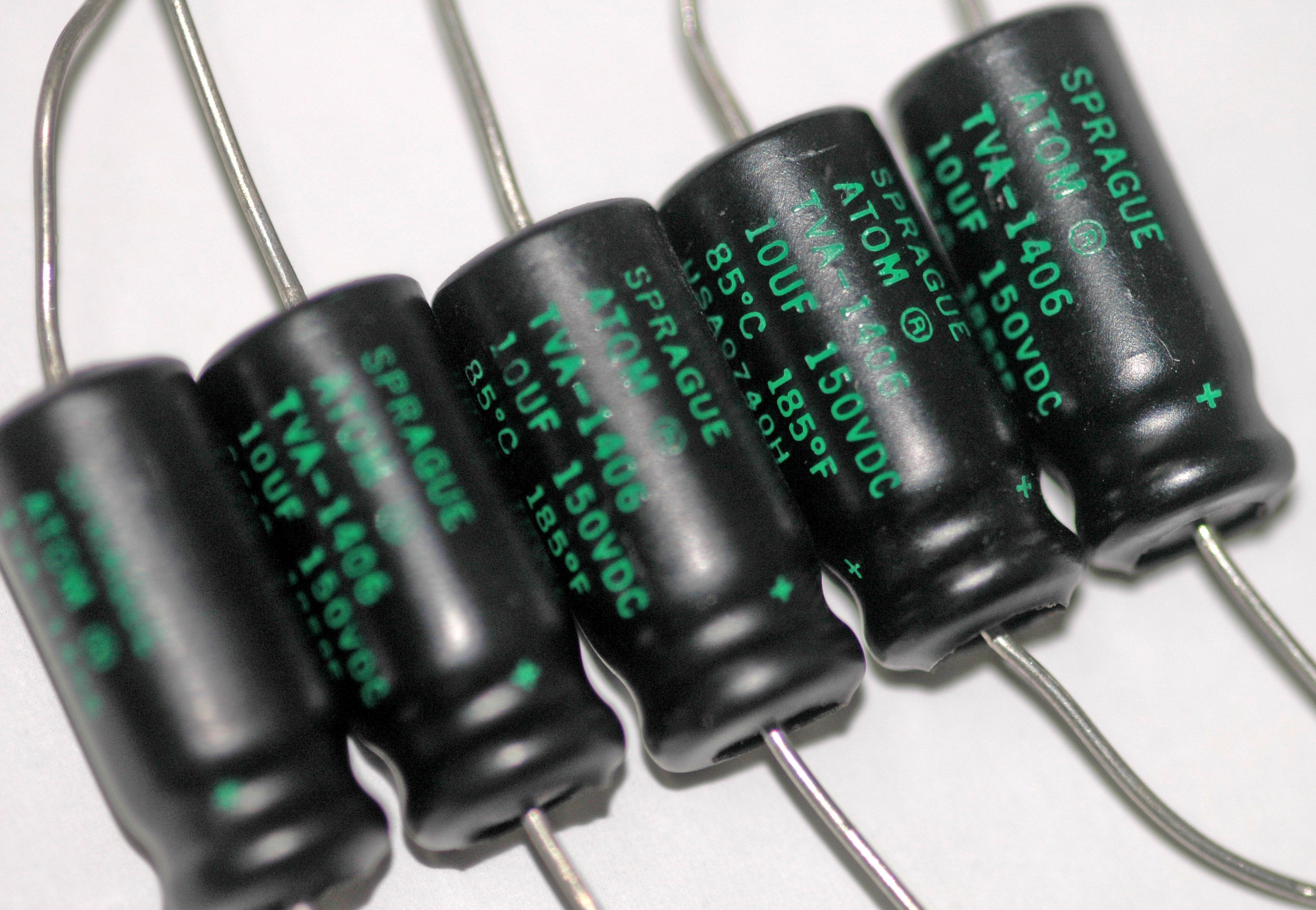
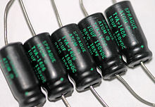 Several axial-lead electrolytic capacitors.
Capacitors may have their connecting leads arranged in many configurations, for example axially or radially. "Axial" means that the leads are on a common axis, typically the axis of the capacitor's cylindrical body – the leads extend from opposite ends. Radial leads might more accurately be referred to as tandem; they are rarely actually aligned along radii of the body's circle, so the term is inexact, although universal. The leads (until bent) are usually in planes parallel to that of the flat body of the capacitor, and extend in the same direction; they are often parallel as manufactured.
Small, cheap discoidal ceramic capacitors have existed since the 1930s, and remain in widespread use. Since the 1980s, surface mount packages for capacitors have been widely used. These packages are extremely small and lack connecting leads, allowing them to be soldered directly onto the surface of printed circuit boards. Surface mount components avoid undesirable high-frequency effects due to the leads and simplify automated assembly, although manual handling is made difficult due to their small size.
Mechanically controlled variable capacitors allow the plate spacing to be adjusted, for example by rotating or sliding a set of movable plates into alignment with a set of stationary plates. Low cost variable capacitors squeeze together alternating layers of aluminum and plastic with a screw. Electrical control of capacitance is achievable with varactors (or varicaps), which are reverse-biased semiconductor diodes whose depletion region width varies with applied voltage. They are used in phase-locked loops, amongst other applications.
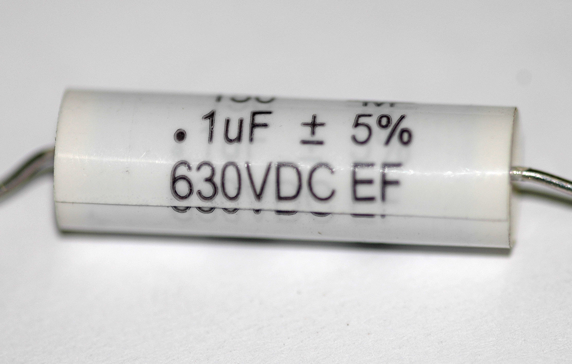
Capacitor markings
Most capacitors have numbers printed on their bodies to indicate their electrical characteristics. Larger capacitors like electrolytics usually display the actual capacitance together with the unit (for example, 220 μF). Smaller capacitors like ceramics, however, use a shorthand consisting of three numbers and a letter, where the numbers show the capacitance in pF (calculated as XY x 10Z for the numbers XYZ) and the letter indicates the tolerance (J, K or M for ±5%, ±10% and ±20% respectively).
Additionally, the capacitor may show its working voltage, temperature and other relevant characteristics.
Example
A capacitor with the text 473K 330V on its body has a capacitance of 47 x 103 pF = 47 nF (±10%) with a working voltage of 330 V.
Applications
Main article: Applications of capacitorsCapacitors have many uses in electronic and electrical systems. They are so common that it is a rare electrical product that does not include at least one for some purpose.
Energy storage
A capacitor can store electric energy when disconnected from its charging circuit, so it can be used like a temporary battery. Capacitors are commonly used in electronic devices to maintain power supply while batteries are being changed. (This prevents loss of information in volatile memory.)
Conventional capacitors provide less than 360 joules per kilogram of energy density, while capacitors using developing technologies could provide more than 2.52 kilojoules per kilogram.[25]
In car audio systems, large capacitors store energy for the amplifier to use on demand. Also for a flash tube a capacitor is used to hold the high voltage.
Pulsed power and weapons
Groups of large, specially constructed, low-inductance high-voltage capacitors (capacitor banks) are used to supply huge pulses of current for many pulsed power applications. These include electromagnetic forming, Marx generators, pulsed lasers (especially TEA lasers), pulse forming networks, radar, fusion research, and particle accelerators.
Large capacitor banks (reservoir) are used as energy sources for the exploding-bridgewire detonators or slapper detonators in nuclear weapons and other specialty weapons. Experimental work is under way using banks of capacitors as power sources for electromagnetic armour and electromagnetic railguns and coilguns.
Power conditioning
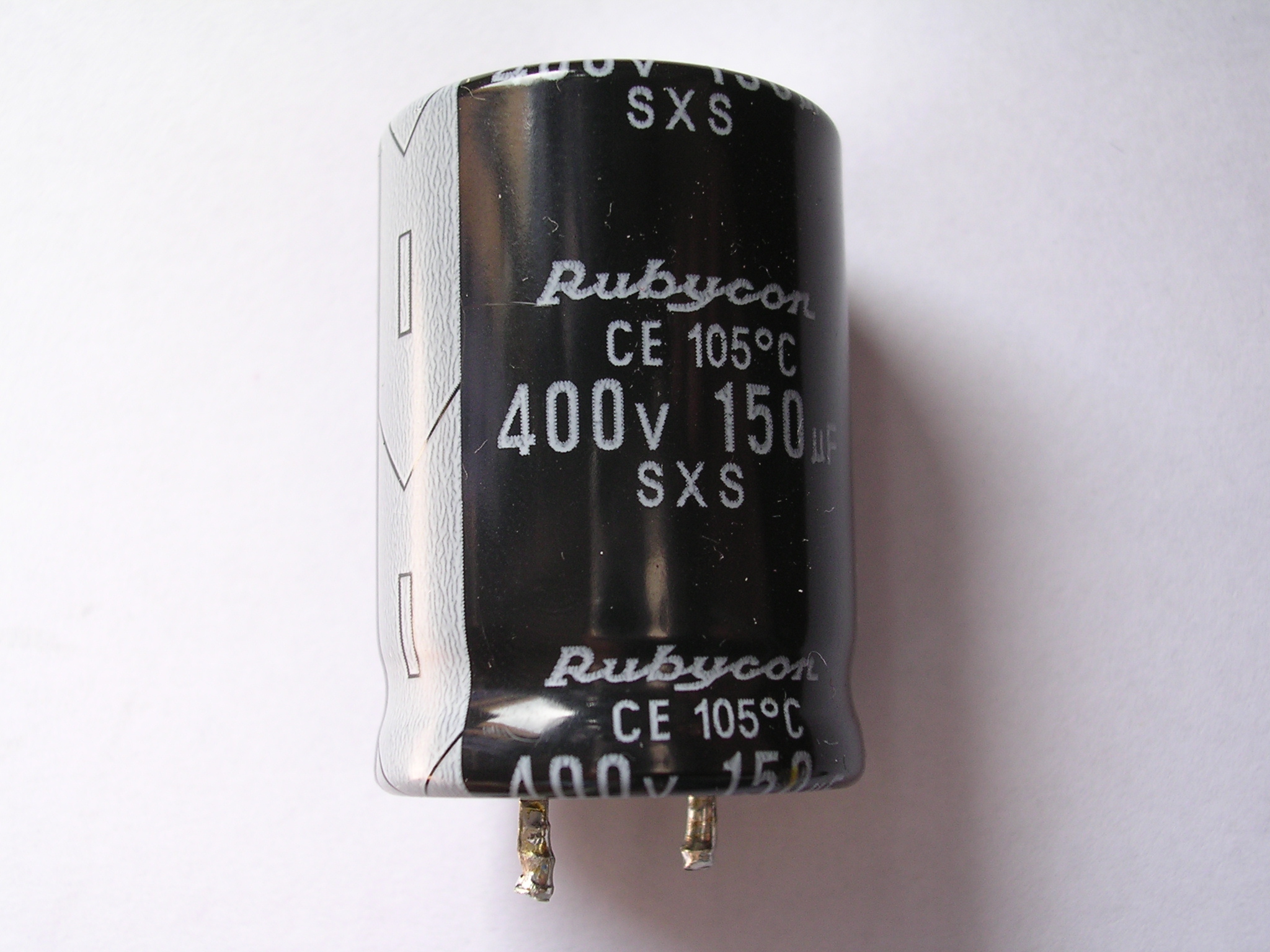
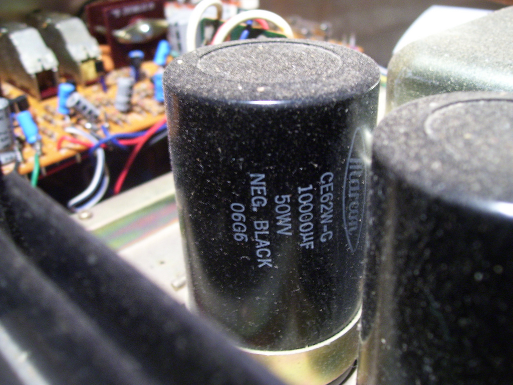
 A 10,000 microfarad capacitor in an amplifier power supply
Reservoir capacitors are used in power supplies where they smooth the output of a full or half wave rectifier. They can also be used in charge pump circuits as the energy storage element in the generation of higher voltages than the input voltage.
Capacitors are connected in parallel with the power circuits of most electronic devices and larger systems (such as factories) to shunt away and conceal current fluctuations from the primary power source to provide a "clean" power supply for signal or control circuits. Audio equipment, for example, uses several capacitors in this way, to shunt away power line hum before it gets into the signal circuitry. The capacitors act as a local reserve for the DC power source, and bypass AC currents from the power supply. This is used in car audio applications, when a stiffening capacitor compensates for the inductance and resistance of the leads to the lead-acid car battery.
Power factor correction
In electric power distribution, capacitors are used for power factor correction. Such capacitors often come as three capacitors connected as a three phase load. Usually, the values of these capacitors are given not in farads but rather as a reactive power in volt-amperes reactive (VAr). The purpose is to counteract inductive loading from devices like electric motors and transmission lines to make the load appear to be mostly resistive. Individual motor or lamp loads may have capacitors for power factor correction, or larger sets of capacitors (usually with automatic switching devices) may be installed at a load center within a building or in a large utility substation.
Supression and coupling
Signal coupling
Main article: capacitive coupling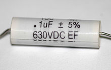 Polyester film capacitors are frequently used as coupling capacitors.
Because capacitors pass AC but block DC signals (when charged up to the applied dc voltage), they are often used to separate the AC and DC components of a signal. This method is known as AC coupling or "capacitive coupling". Here, a large value of capacitance, whose value need not be accurately controlled, but whose reactance is small at the signal frequency, is employed.
Decoupling
Main article: decoupling capacitorA decoupling capacitor is a capacitor used to protect one part of a circuit from the effect of another, for instance to suppress noise or transients. Noise caused by other circuit elements is shunted through the capacitor, reducing the effect they have on the rest of the circuit. It is most commonly used between the power supply and ground. An alternative name is bypass capacitor as it is used to bypass the power supply or other high impedance component of a circuit.
Noise filters and snubbers
When an inductive circuit is opened, the current through the inductance collapses quickly, creating a large voltage across the open circuit of the switch or relay. If the inductance is large enough, the energy will generate a spark, causing the contact points to oxidize, deteriorate, or sometimes weld together, or destroying a solid-state switch. A snubber capacitor across the newly opened circuit creates a path for this impulse to bypass the contact points, thereby preserving their life; these were commonly found in contact breaker ignition systems, for instance. Similarly, in smaller scale circuits, the spark may not be enough to damage the switch but will still radiate undesirable radio frequency interference (RFI), which a filter capacitor absorbs. Snubber capacitors are usually employed with a low-value resistor in series, to dissipate energy and minimize RFI. Such resistor-capacitor combinations are available in a single package.
Capacitors are also used in parallel to interrupt units of a high-voltage circuit breaker in order to equally distribute the voltage between these units. In this case they are called grading capacitors.
In schematic diagrams, a capacitor used primarily for DC charge storage is often drawn vertically in circuit diagrams with the lower, more negative, plate drawn as an arc. The straight plate indicates the positive terminal of the device, if it is polarized (see electrolytic capacitor).
Motor starters
Main article: motor capacitorIn single phase squirrel cage motors, the primary winding within the motor housing is not capable of starting a rotational motion on the rotor, but is capable of sustaining one. To start the motor, a secondary "Start" winding has a series non-polarized starting capacitor to introduce a lead in the sinusoidal current. When the secondary(Start) winding is placed at an angle with respect to the primary(Run) winding, a rotating electric field is created. The force of the rotational field is not constant, but is sufficient to start the rotor spinning. When the rotor comes close to operating speed, a centrifugal switch (or current-sensitive relay in series with the main winding) disconnects the capacitor. The start capacitor is typically mounted to the side of the motor housing. These are called capacitor-start motors, that have relatively high starting torque. Typically they can have up-to 4 times as much starting torque than a split-phase motor and are used on applications such as compressors, pressure washers and any small device requiring high starting torques.
Capacitor-run induction motors have a permanently connected phase-shifting capacitor in series with a second winding. The motor is much like a two-phase induction motor.
Motor-starting capacitors are typically non-polarized electrolytic types, while running capacitors are conventional paper or plastic film dielectric types.
Signal processing
The energy stored in a capacitor can be used to represent information, either in binary form, as in DRAMs, or in analogue form, as in analog sampled filters and CCDs. Capacitors can be used in analog circuits as components of integrators or more complex filters and in negative feedback loop stabilization. Signal processing circuits also use capacitors to integrate a current signal.
Tuned circuits
Capacitors and inductors are applied together in tuned circuits to select information in particular frequency bands. For example, radio receivers rely on variable capacitors to tune the station frequency. Speakers use passive analog crossovers, and analog equalizers use capacitors to select different audio bands.
The resonant frequency f of a tuned circuit is a function of the inductance (L) and capacitance (C) in series, and is given by:
where L is in henries and C is in farads.
Sensing
-
Main article: capacitive sensing
Most capacitors are designed to maintain a fixed physical structure. However, various factors can change the structure of the capacitor, and the resulting change in capacitance can be used to sense those factors.
Changing the dielectric:
- The effects of varying the physical and/or electrical characteristics of the dielectric can be used for sensing purposes. Capacitors with an exposed and porous dielectric can be used to measure humidity in air. Capacitors are used to accurately measure the fuel level in airplanes; as the fuel covers more of a pair of plates, the circuit capacitance increases.
Changing the distance between the plates:
- Capacitors with a flexible plate can be used to measure strain or pressure. Industrial pressure transmitters used for process control use pressure-sensing diaphragms, which form a capacitor plate of an oscillator circuit. Capacitors are used as the sensor in condenser microphones, where one plate is moved by air pressure, relative to the fixed position of the other plate. Some accelerometers use MEMS capacitors etched on a chip to measure the magnitude and direction of the acceleration vector. They are used to detect changes in acceleration, e.g. as tilt sensors or to detect free fall, as sensors triggering airbag deployment, and in many other applications. Some fingerprint sensors use capacitors. Additionally, a user can adjust the pitch of a theremin musical instrument by moving his hand since this changes the effective capacitance between the user's hand and the antenna.
Changing the effective area of the plates:
- Capacitive touch switches are now used on many consumer electronic products.
Hazards and safety
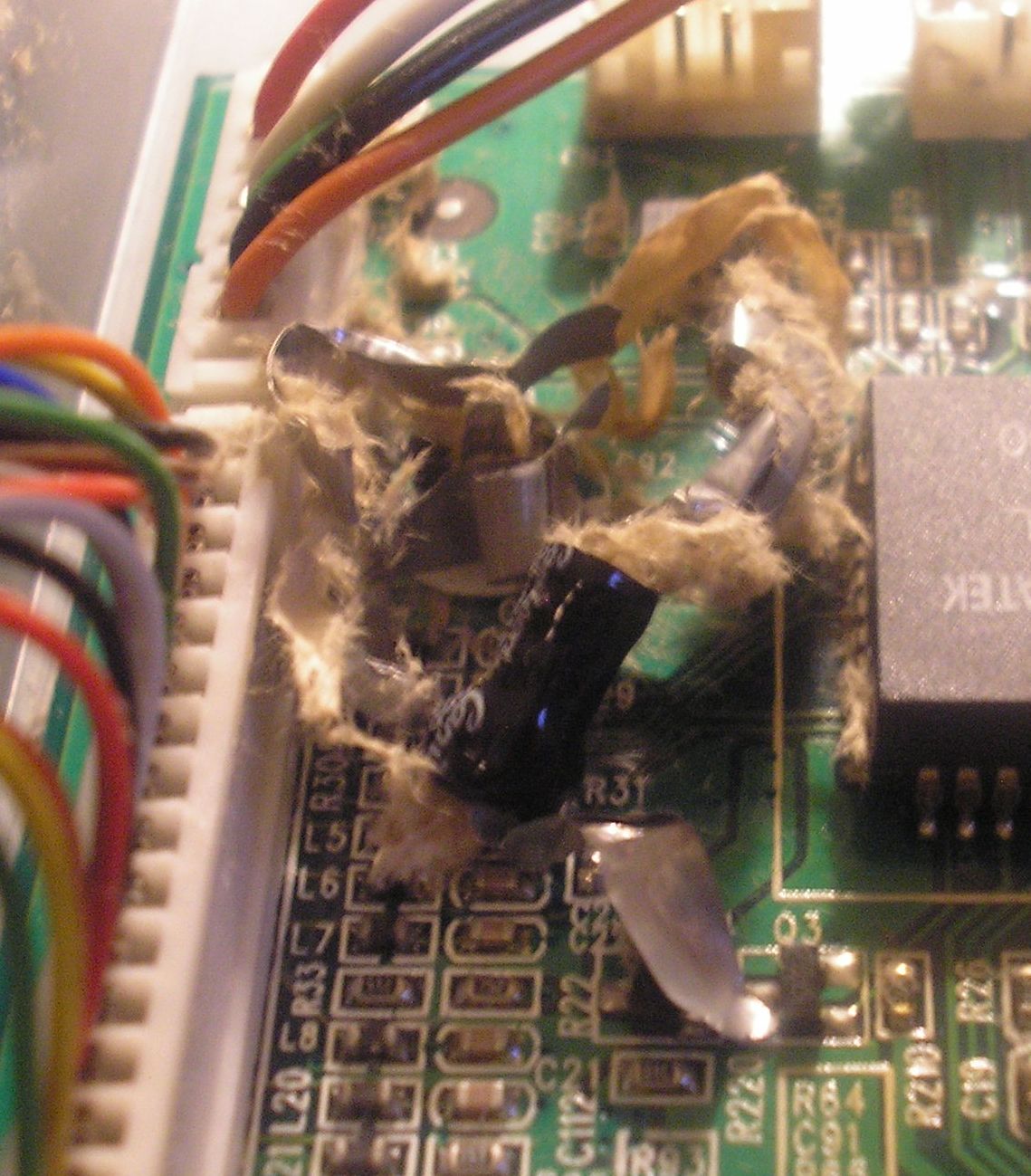
 Catastrophic failure
Capacitors may retain a charge long after power is removed from a circuit; this charge can cause dangerous or even potentially fatal shocks or damage connected equipment. For example, even a seemingly innocuous device such as a disposable camera flash unit powered by a 1.5 volt AA battery contains a capacitor which may be charged to over 300 volts. This is easily capable of delivering a shock. Service procedures for electronic devices usually include instructions to discharge large or high-voltage capacitors. Capacitors may also have built-in discharge resistors to dissipate stored energy to a safe level within a few seconds after power is removed. High-voltage capacitors are stored with the terminals shorted, as protection from potentially dangerous voltages due to dielectric absorption.
Some old, large oil-filled capacitors contain polychlorinated biphenyls (PCBs). It is known that waste PCBs can leak into groundwater under landfills. Capacitors containing PCB were labelled as containing "Askarel" and several other trade names. PCB-filled capacitors are found in very old (pre-1975) fluorescent lamp ballasts, and other applications.
Capacitors may catastrophically fail when subjected to voltages or currents beyond their rating, or as they reach their normal end of life. Dielectric or metal interconnection failures may create arcing that vaporizes the dielectric fluid, resulting in case bulging, rupture, or even an explosion. Capacitors used in RF or sustained high-current applications can overheat, especially in the center of the capacitor rolls. Capacitors used within high-energy capacitor banks can violently explode when a short in one capacitor causes sudden dumping of energy stored in the rest of the bank into the failing unit. High voltage vacuum capacitors can generate soft X-rays even during normal operation. Proper containment, fusing, and preventive maintenance can help to minimize these hazards.
High-voltage capacitors can benefit from a pre-charge to limit in-rush currents at power-up of high voltage direct current (HVDC) circuits. This will extend the life of the component and may mitigate high-voltage hazards.
See also
- Capacitance meter
- Capacitive displacement sensor
- Capacitor plague: capacitor failures in switch mode power supplies
- Circuit design
- Decoupling capacitor
- Dielectrics
- Electric displacement field
Notes
- ^ Henry Smith Williams. "A History of Science Volume II, Part VI: The Leyden Jar Discovered". http://www.worldwideschool.org/library/books/sci/history/AHistoryofScienceVolumeII/chap49.html.
- ^ Houston, Edwin J. (1905). Electricity in Every-day Life. P. F. Collier & Son. http://books.google.com/?id=ko9BAAAAIAAJ&pg=PA71&dq=jar+%22von+Kleist%22.
- ^ Keithley, Joseph (1999). The Story of Electrical and Magnetic Measurements From 500 BC to the 1940s. IEEE Press. p. 23. ISBN 0-7803-1193-0. http://books.google.com/?id=uwgNAtqSHuQC&printsec=frontcover&q.
- ^ Isaacson, Walter (2003). Benjamin Franklin. Simon and Schuster. p. 136. ISBN 0684807610, 9780684807614. http://books.google.com/?id=oIW915dDMBwC&lpg=PA135&dq=%22benjamin%20franklin%22%20leyden%20jar&pg=PA136#v=onepage&q=.
- ^ Franklin, Benjamin (1749-04-29). "Experiments & Observations on Electricity: Letter IV to Peter Collinson" (PDF). pp. (page 28). http://www.chemteam.info/Chem-History/Franklin-1749/Franklin-1749-all.pdf. Retrieved 2009-08-09.
- ^ Morse, Robert A., Ph.D. (September 2004). "Franklin and Electrostatics—Ben Franklin as my Lab Partner" (PDF). Wright Center for Science Education. Tufts University. pp. (page 23). http://www.tufts.edu/as/wright_center/personal_pages/bob_m/04_Franklin_Lab_Part_IV.pdf. Retrieved 2009-08-10. "After Volta’s discovery of the electrochemical cell in 1800, the term was then applied to a group of electrochemical cells"
- ^ "Sketch of Alessandro Volta". The Popular Science Monthly (New York): pp. 118–119. May–Oct 1892. http://books.google.com/books?id=eCADAAAAMBAJ&pg=PA117&source=gbs_toc_r&cad=1#v=onepage&q&f=false.
- ^ a b Ulaby, p.168
- ^ Ulaby, p.157
- ^ a b Ulaby, p.169
- ^ Hammond, P, Electromagnetism for Engineers, pp44-45, Pergamon Press, 1965.
- ^ Dorf, p.263
- ^ Dorf, p.260
- ^ "Capacitor charging and discharging : DC CIRCUITS". All About Circuits. http://www.allaboutcircuits.com/vol_6/chpt_3/17.html. Retrieved 2009-02-19.
- ^ F. F. Mazda, Discrete electronic components, Cambridge University Press,1981 ISBN 0521234700, page 71
- ^ http://electrochem.cwru.edu/encycl/misc/c04-appguide.pdf Retrieved 10/28/2011
- ^ Ulaby, p.170
- ^ S. T. Pai and Qi Zhang (1995). Introduction to High Power Pulse Technology. World Scientific. ISBN 9810217145. http://books.google.com/?id=spZ_H4nwIN0C&pg=PA47&dq=breakdown+field+energy-density+dielectric.
- ^ Stephen A. Dyer (ed) Survey of instrumentation and measurement ,Wiley-IEEE, 2001 ISBN 047139484X page 397
- ^ Scherz, P, Practical Electronics for Inventors, p100, McGraw-Hill Professional, 2006, ISBN 0071452818.
- ^ Bird, J, Electrical Circuit Theory and Technology, p501, Newnes, 2007, ISBN 075068139X.
- ^ Ceramic Capacitor Aging Made Simple
- ^ http://www.ga-esi.com/support/ep/tech-bulletins/voltage-reversal.pdf
- ^ Ask The Applications Engineer – 21 , Steve Guinta, Analog Devices
- ^ Next-gen car solution? Scientists expand uses for electrostatic capacitor
References
- Dorf, Richard C.; Svoboda, James A. (2001). Introduction to Electric Circuits (5th ed.). New York: John Wiley and Sons, Inc.. ISBN 0-471-38689-8.
- Ulaby, Fawwaz T. (1999). Fundamentals of Applied Electromagnetics (1999 ed.). Upper Saddle River, New Jersey: Prentice-Hall. ISBN 0-13-011554-1.
- Zorpette, Glenn (2005). "Super Charged: A Tiny South Korean Company is Out to Make Capacitors Powerful enough to Propel the Next Generation of Hybrid-Electric Cars". IEEE Spectrum 42 (1): 32. doi:10.1109/MSPEC.2005.1377872. ISSN 0018-9235. http://www.spectrum.ieee.org/jan05/2777.
- The ARRL Handbook for Radio Amateurs (68th ed.). Newington CT USA: The Amateur Radio Relay League. 1991.
- Huelsman, Lawrence P. (1972). Basic Circuit Theory with Digital Computations. Series in computer applications in electrical engineering. Englewood Cliffs: Prentice-Hall. ISBN 0-13-057430-9.
- Philosophical Transactions of the Royal Society LXXII, Appendix 8, 1782 (Volta coins the word condenser)
- A. K. Maini "Electronic Projects for Beginners", "Pustak Mahal", 2nd Edition: March, 1998 (INDIA)
- Spark Museum (von Kleist and Musschenbroek)
- Biography of von Kleist
External links
- Howstuffworks.com: How Capacitors Work
- CapSite 2009: Introduction to Capacitors
- Capacitor Tutorial – Includes how to read capacitor temperature codes
- Introduction to Capacitor and Capacitor codes
Electronic components Semiconductors Avalanche diode • Barretter • Darlington transistor • DIAC • Diode • Field-effect transistor (FET) • Insulated-gate bipolar transistor (IGBT) • JFET • Light-emitting diode (LED) • Memristor • MOSFET • Photodetector • PIN diode • Silicon-controlled rectifier (SCR) • Thyristor • Transistor • TRIAC • Unijunction transistor (UJT) • Zener diodeVacuum tubes Vacuum tubes (RF) Backward wave oscillator (BWO) • Cavity magnetron • Crossed-field amplifier • Gyrotron • Inductive output tube (IOT) • Klystron • Maser • Traveling-wave tubeAdjustable Passive Connector (Electrical power, Baseband, RF) • Ferrite • Fuse • Resettable fuse • Resistor (Thermistor) • TransformerReactive Categories:- Capacitors
- Energy storage


Wikimedia Foundation. 2010.