- Electronic symbol
-
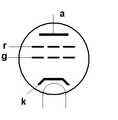
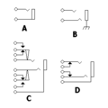
An electronic symbol is a pictogram used to represent various electrical and electronic devices (such as wires, batteries, resistors, and transistors) in a schematic diagram of an electrical or electronic circuit. These symbols can (because of remaining traditions) vary from country to country, but are today to a large extent internationally standardized. Some symbols (such as those of vacuum tubes) became virtually extinct with the development of new technologies.
Contents
Standards for symbols
There are several national and international standards for graphical symbols in circuit diagrams, in particular:
- IEC 60617 (also known as British Standard BS 3939)
- ANSI standard Y32 (also known as IEEE Std 315)
- Australian Standard AS 1102
Different symbols may be used depending on the discipline using the drawing. For example, lighting and power symbols used as part of architectural drawings may be different from symbols for devices used in electronics. National and local variations to international standards also exist.
Reference designations
A reference designator unambiguously identifies a component in an electrical schematic (circuit diagram) or on a printed circuit board (PCB). The reference designator usually consists of one or two letters followed by a number, e.g. R13, C1002. The number is sometimes followed by a letter, indicating that components are grouped or matched with each other, e.g. R17A, R17B. IEEE 315 contains a list of Class Designation Letters to use for electrical and electronic assemblies. For example, the letter R is a reference prefix for the resistors of an assembly, C for capacitors, K for relays.
IEEE 200-1975 or "Standard Reference Designations for Electrical and Electronics Parts and Equipments" is a standard that was used to define referencing naming systems for collections of electronic equipment. IEEE 200 was ratified in 1975. The IEEE renewed the standard in the 1990s, but withdrew it from active support shortly thereafter. This standard also has an ANSI document number ANSI Y32.16-1975. They are the same document.
This standard codified information from, among other sources, a United States military standard MIL-STD-16 which dates back to at least the 1950s in American industry.
To replace IEEE 200-1975, a standards body for Mechanical Engineers, ASME, initiated the new standard ASME Y14.44-2008.
This standard along with IEEE 315-1975 provide the electrical designer with guidance on how to properly reference and annotate everything from a simple circuit board to a complete enclosure all the way to a collection of these assemblies.
It breaks down a system into units, and then any number of sub-assemblies. The Unit is the highest level of demarcation in a system and is always a numeral. Subsequent demarcation are called assemblies and always have the Class Letter "A" as a prefix following by a sequential number starting with 1. Any number of sub-assemblies may be defined until finally reaching the component.
Especially valuable is the method of referencing and annotating cables plus their connectors within and outside assemblies. Examples:
- 1A1A44J5 - Unit 1, Assembly 1, Sub-Assembly 44, Jack 5 (J5 is a connector on a box referenced as A44)
- 1A1A45J333 - Unit 1, Assembly 1, Sub-Assembly 45, Jack 333 (J333 is a connector on a box referenced as A45)
A cable connecting these two might be:
- 1A1W35 - In the assembly A1 is a cable called W35.
Connectors on this cable would be designated:
- 1A1W35P1
- 1A1W35P2
ASME Y14.44-2008 continues the convention of Plug P and Jack J when assigning references for connectors in electrical assemblies where a J (or jack) is the more fixed and P (or plug) is the less fixed of a connector pair without regard to the gender of the connector contacts.
The construction of reference designators is covered by IEEE 200-1975/ANSI Y32.16-1975[1] (replaced by ASME Y14.44-2008[2]) and IEEE-315-1975[3]. The table below lists designators commonly used, and does not comply with the standard.
Designator Component Type AT Attenuator BR Bridge rectifier BT Battery C Capacitor CN Capacitor network D Diode (including zeners, thyristors and LEDs) DL Delay line DS Display F Fuse FB or FEB Ferrite bead FD Fiducial J Jack connector (female) JP Link (Jumper) K Relay L Inductor LS Loudspeaker or buzzer M Motor MK Microphone MP Mechanical part (including screws and fasteners) P Plug connector (male) PS Power supply Q Transistor (all types) R Resistor RN Resistor network RT Thermistor RV Varistor S Switch (all types, including push-buttons) T Transformer TC Thermocouple TUN Tuner TP Test point U Integrated circuit V Vacuum Tube VR Variable Resistor (potentiometer or rheostat) X Transducer not matching any other category Y Crystal or oscillator Z Zener Diode Component name abbreviations widely used in industry:
- AE: aerial, antenna
- B: battery
- BR: bridge rectifier
- C: capacitor
- CRT:cathode ray tube
- D or CR: diode
- DSP:digital signal processor
- F: fuse
- FET:field effect transistor
- GDT: gas discharge tube
- IC: integrated circuit
- J: wire link ("jumper")
- JFET: junction gate field-effect transistor
- L: inductor
- LCD:Liquid crystal display
- LDR: light dependent resistor
- LED: light emitting diode
- LS: speaker
- M: motor
- MCB: circuit breaker
- Mic: microphone
- MOSFET:Metal oxide semiconductor field effect transistor
- Ne: neon lamp
- OP: Operational Amplifier
- PCB: printed circuit board
- PU: pickup
- Q: transistor
- R: resistor
- RLA: RY: relay
- SCR: silicon controlled rectifier
- SW: switch
- T: transformer
- TFT:thin film transistor(display)
- TH: thermistor
- TP: test point
- Tr: transistor
- U: integrated circuit
- V: valve (tube)
- VC: variable capacitor
- VFD: vacuum fluorescent display
- VLSI:very large scale integration
- VR: variable resistor
- X: crystal, ceramic resonator
- XMER: transformer
- XTAL: crystal
- Z or ZD: Zener diode
Gallery of common electronic symbols
Resistors
-
Potentiometer: American
Capacitors
Transistors
Diodes
Vacuum tubes
Switches
Miscellaneous
-
Batteries, single cell, multi-cell
-
Transformer, with center tap
See also
References
- ^ Standard Reference Designations for Electrical and Electronics Parts and Equipments: IEEE 200-1975 (Reaffirmed 1988): Section 4.1.5.3 (2). IEEE and ANSI, New York, NY. 1975.
- ^ Reference Designations for Electrical and Electronics Parts and Equipment: ASME Y14.44-2008 (Replaced IEEE 200-1975). ASME, Fairfield, NJ. 2008. http://catalog.asme.org/Codes/PrintBook/Y1444_Reference_Designations.cfm.
- ^ Graphic Symbols for Electrical and Electronics Diagrams (Including Reference Designation Letters): IEEE-315-1975 (Reaffirmed 1993): Section 22. IEEE and ANSI, New York, NY. 1993.
External links
Categories:- Electronic engineering
- Pictograms
Wikimedia Foundation. 2010.


