- Electronic circuit
-
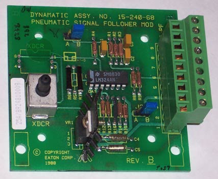
 A circuit built on a printed circuit board (PCB).
An electronic circuit is composed of individual electronic components, such as resistors, transistors, capacitors, inductors and diodes, connected by conductive wires or traces through which electric current can flow. The combination of components and wires allows various simple and complex operations to be performed: signals can be amplified, computations can be performed, and data can be moved from one place to another.[1] Circuits can be constructed of discrete components connected by individual pieces of wire, but today it is much more common to create interconnections by photolithographic techniques on a laminated substrate (a printed circuit board or PCB) and solder the components to these interconnections to create a finished circuit. In an Integrated Circuit or IC, the components and interconnections are formed on the same substrate, typically a semiconductor such as silicon or (less commonly) gallium arsenide.[2]
Breadboards, perfboards or stripboards are common for testing new designs. They allow the designer to make quick changes to the circuit during development.
An electronic circuit can usually be categorized as an analog circuit, a digital circuit or a mixed-signal circuit (a combination of analog circuits and digital circuits).
Contents
Analog circuits
Main article: Analog electronics A circuit diagram representing an analog circuit, in this case a simple amplifier.
Analog electronic circuits are those in which current or voltage may vary continuously with time to correspond to the information being represented. Analog circuitry is constructed from two fundamental building blocks: series and parallel circuits. In a series circuit, the same current passes through a series of components. A string of Christmas lights is a good example of a series circuit: if one goes out, they all do. In a parallel circuit, all the components are connected to the same voltage, and the current divides between the various components according to their resistance.
 A simple schematic showing wires, a resistor, and a battery.
The basic components of analog circuits are wires, resistors, capacitors, inductors, diodes, and transistors. (Recently, memristors have been added to the list of available components.) Analog circuits are very commonly represented in schematic diagrams, in which wires are shown as lines, and each component has a unique symbol. Analog circuit analysis employs Kirchhoff's circuit laws: all the currents at a node (a place where wires meet) must add to 0, and the voltage around a closed loop of wires is 0. Wires are usually treated as ideal zero-voltage interconnections; any resistance or reactance is captured by explicitly adding a parasitic element, such as a discrete resistor or inductor. Active components such as transistors are often treated as controlled current or voltage sources: for example, a field-effect transistor can be modeled as a current source from the source to the drain, with the current controlled by the gate-source voltage.
When the circuit size is comparable to a wavelength of the relevant signal frequency, a more sophisticated approach must be used. Wires are treated as transmission lines, with (hopefully) constant characteristic impedance, and the impedances at the start and end determine transmitted and reflected waves on the line. Such considerations typically become important for circuit boards at frequencies above a GHz; integrated circuits are smaller and can be treated as lumped elements for frequencies less than 10 GHz or so.
An alternative model is to take independent power sources and induction as basic electronic units; this allows modeling frequency dependent negative resistors, gyrators, negative impedance converters, and dependent sources as secondary electronic components.
Digital circuits
Main article: Digital electronicsIn digital electronic circuits, electric signals take on discrete values, to represent logical and numeric values.[3] These values represent the information that is being processed. In the vast majority of cases, binary encoding is used: one voltage (typically the more positive value) represents a binary '1' and another voltage (usually a value near the ground potential, 0 V) represents a binary '0'. Digital circuits make extensive use of transistors, interconnected to create logic gates that provide the functions of Boolean logic: AND, OR, NOT, and all possible combinations thereof. Transistors interconnected so as to provide positive feedback are used as latches and flip flops, circuits that have two or more metastable states, and remain in one of these states until changed by an external input. Digital circuits therefore can provide both logic and memory, enabling them to perform arbitrary computational functions. (Memory based on flip-flops is known as Static random-access memory(SRAM). Memory based on the storage of charge in a capacitor, dynamic random-access memory(DRAM) is also widely used.)
Digital circuits are fundamentally easier to design than analog circuits for the same level of complexity, because each logic gate regenerates the binary signal, so the designer need not account for distortion, gain control, offset voltages, and other concerns faced in an analog design. As a consequence, extremely complex digital circuits, with billions of logic elements integrated on a single silicon chip, can be fabricated at low cost. Such digital integrated circuits are ubiquitous in modern electronic devices, such as calculators, mobile phone handsets, and computers.
Digital circuitry is used to create general purpose computing chips, such as microprocessors, and custom-designed logic circuits, known as Application Specific Integrated Circuits (ASICs). Field Programmable Gate Arrays (FPGAs), chips with logic circuitry whose configuration can be modified after fabrication, are also widely used in prototyping and development.
Mixed-signal circuits
Mixed-signal or hybrid circuits contain elements of both analog and digital circuits. Examples include comparators, timers, PLLs, ADCs (analog-to-digital converters), and DACs (digital-to-analog converters). Most modern radio and communications circuitry uses mixed signal circuits. For example, in a receiver, analog circuitry is used to amplify and frequency-convert signals so that they reach a suitable state to be converted into digital values, after which further signal processing can be performed in the digital domain.
References
External links
Categories:- Electronic engineering
- Electronics terms
- Electronic circuits


Wikimedia Foundation. 2010.