- Marx generator
-
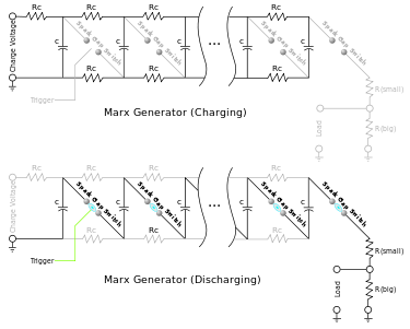 Marx generator diagrams; Although the left capacitor has the greatest charge rate, the generator is typically allowed to charge for a long period of time, and all capacitors eventually reach the same charge voltage.
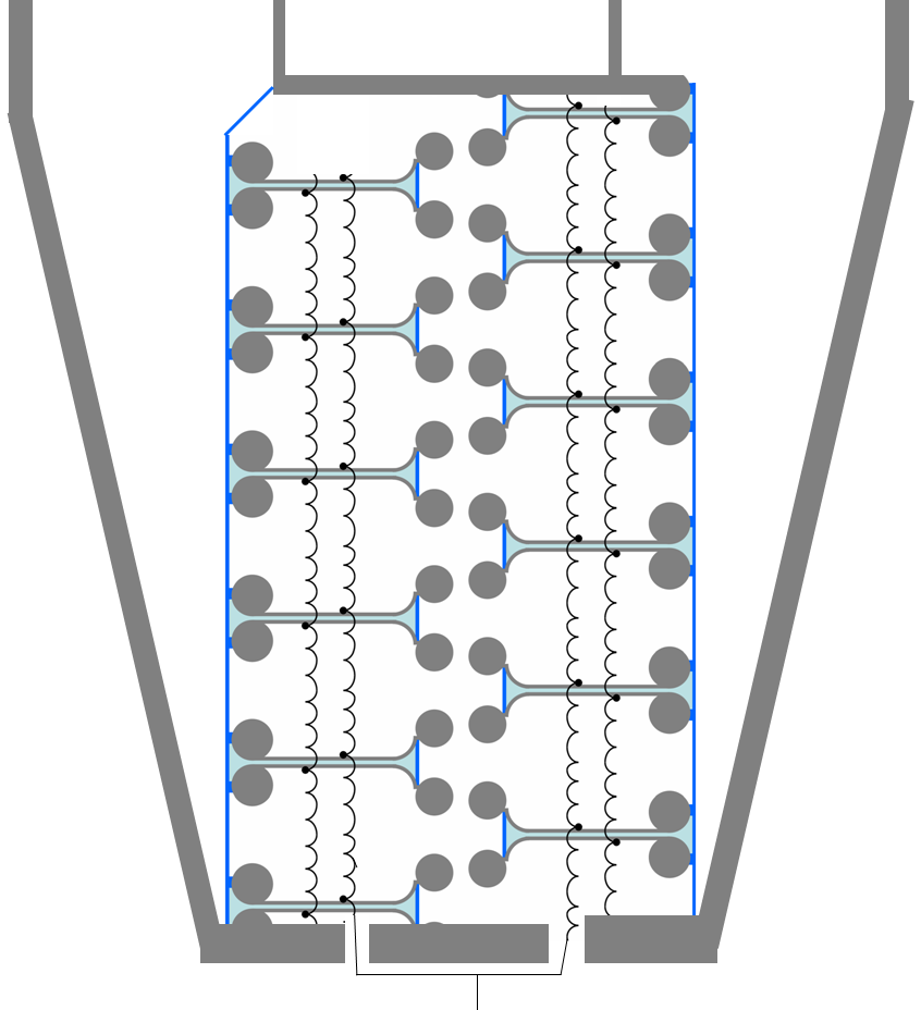
 To deliver 5 ns rise time pulses, the Marx generator is often built into a coaxial wave guide. The spark gaps are placed as close as possible together for maximum UV light exchange for minimum jitter. DC HV comes from underneath, pulsed HV leaves at the top into the coaxial line. The double line of spheres in the middle are the spark gaps, all other spheres are to avoid corona discharge. Blue=water capacitor. Grey=solid metal. Black= thin wire. The outer conductor also functions as a vessel, so that the gas and the pressure can be optimized.
A Marx generator is an electrical circuit first described by Erwin Otto Marx in 1924. Its purpose is to generate a high-voltage pulse. Marx generators are often used to simulate the effects of lightning on power line gear and aviation equipment. A bank of 36 Marx generators is used by Sandia National Laboratories to generate X-rays in their Z Machine.
Contents
Principle
A number of capacitors are charged in parallel to a given voltage, V, and then connected in series by spark gap switches, ideally producing a voltage of V multiplied by the number, n, of capacitors (or stages). Due to various practical constraints, the output voltage is somewhat less than n×V.
Optimization
Proper performance depends upon selection of capacitor and the timing of the discharge. Switching times can be improved by doping of the electrodes with radioactive isotopes caesium 137 or nickel 63, and by orienting the spark gaps so that ultraviolet light from a firing spark gap switch illuminates the remaining open spark gaps.[1] Insulation of the high voltages produced is often accomplished by immersing the Marx generator in transformer oil or a high pressure electronegative gas such as sulfur hexafluoride (SF6).
Note that the less resistance there is between the capacitor and the charging power supply, the faster it will charge. Thus, in this design, those closer to the power supply will charge quicker than those farther away. If the generator is allowed to charge long enough, all capacitors will attain the same voltage.
In the ideal case, the closing of the switch closest to the charging power supply applies a voltage 2V to the second switch. This switch will then close, applying a voltage 3V to the third switch. This switch will then close, resulting in a cascade down the generator that produces nV at the generator output (again, only in the ideal case).
The first switch may be allowed to spontaneously break down (sometimes called a self break) during charging if the absolute timing of the output pulse is unimportant. However, it is usually intentionally triggered once all the capacitors in the Marx bank have reached full charge, either by reducing the gap distance, by pulsing an additional trigger electrode (such as a Trigatron), by ionising the air in the gap using a pulsed laser, or by reducing the air pressure within the gap.
The charging resistors, Rc, need to be properly sized for both charging and discharging. They are sometimes replaced with inductors for improved efficiency and faster charging. In many generators the resistors are made from plastic or glass tubing filled with dilute copper sulfate solution. These liquid resistors overcome many of the problems experienced by more-conventional solid resistive materials, which have a tendency to lower their resistance over time under high voltage conditions.
Short pulses
The Marx generator is also used to generate short high-power pulses for Pockels cells, driving a TEA laser, ignition of the conventional explosive of a nuclear weapon, and radar pulses.
Shortness is relative, as the switching time of even high-speed versions is not less than 1 ns, and thus many low-power electronic devices are faster. In the design of high-speed circuits, electrodynamics is important, and the Marx generator supports this insofar as it uses short thick leads between its components, but the design is nevertheless essentially an electrostatic one. (In electrodynamic terms, when the first stage breaks down it creates a spherical electromagnetic wave whose electric field vector is opposed to the static high voltage. This moving electromagnetic field has the wrong orientation to trigger the next stage, and may even reach the load; such noise in front of the edge is undesirable in many switching applications. If the generator is inside a tube of (say) 1 m diameter, it requires around 10 wave reflections for the field to settle to static conditions, which restricts pulse leading edge width to 30 ns or more. Smaller devices are of course faster.) When the first gap breaks down, pure electrostatic theory predicts that the voltage across all stages rises. However, stages are coupled capacitively to ground and serially to each other, and thus each stage encounters a voltage rise that is increasingly weaker the further the stage is from the switching one; the adjacent stage to the switching one therefore encounters the largest voltage rise, and thus switches in turn. As more stages switch, the voltage rise to the remainder increases, which speeds up their operation. Thus a voltage rise fed into the first stage becomes amplified and steepened at the same time.
The speed of a switch is determined by the speed of the charge carriers, which gets higher with higher voltage, and by the current available to charge the inevitable parasitic capacity. In solid-state avalanche devices, a high voltage automatically leads to high current. Because the high voltage is applied only for a short time, solid-state switches will not heat up excessively. As compensation for the higher voltages encountered, the later stages have to carry lower charge too. Stage cooling and capacitor recharging also go well together.
Stage variants
Avalanche diodes can replace the spark gap for stage voltages less than 500 volts. The charge carriers easily leave the electrodes, so no extra ionisation is needed and jitter is low. The diodes also have a longer lifetime than spark gaps.[citation needed]
A speedy switching device is an NPN avalanche transistor fitted with a coil between base and emitter. The transistor is initially switched off and about 300 volts exists across its collector-base junction. This voltage is high enough that a charge carrier in this region can create more carriers by impact ionisation, but the probability is too low to form a proper avalanche; instead a somewhat noisy leakage current flows. When the preceding stage switches, the emitter-base junction is pushed into forward bias and the collector-base junction enters full avalanche mode, so charge carriers injected into the collector-base region multiply in a chain reaction. Once the Marx generator has completely fired, voltages everywhere drop, each switch avalanche stops, its matched coil puts its base-emitter junction into reverse bias, and the low static field allows remaining charge carriers to drain out of its collector-base junction.
Applications
One application is so-called boxcar switching of a Pockels cell. Four Marx generators are used, each of the two electrodes of the Pockels cell being connected to a positive pulse generator and a negative pulse generator. Two generators of opposite polarity, one on each electrode, are first fired to charge the Pockels cell into one polarity. This will also partly charge the other two generators but not trigger them, because they have been only partly charged beforehand. Leakage through the Marx resistors needs to be compensated by a small bias current through the generator. At the trailing edge of the boxcar, the two other generators are fired to "reverse" the cell.
Marx generators are used to provide high-voltage pulses for the testing of insulation of electrical apparatus such as large power transformers, or insulators used for supporting power transmission lines. Voltages applied may exceed 2 million volts for high-voltage apparatus.
See also
- Cockcroft-Walton generator - a similar circuit which has the same "ladder" structure. CW generator produces a constant DC.
- Explosively pumped flux compression generator - A solution to the opposite problem of creating huge currents at lower voltages.
- Transformer - An inductive circuit that is analogous to using mechanical gears to increase torque or speed. Can convert AC from one voltage and current, to another. Any increase in voltage will result in a reduction in current. The opposite is also true.
References
- ^ E. Kuffel, W. S. Zaengl, J. Kuffel High voltage engineering: fundamentals,Newnes, 2000 ISBN 0750636343, pages 63, 70
Further reading
- M. Obara, "Strip-Line Multichannel-Surface-Spark-Gap-Type Marx Generator for Fast Discharge Lasers", IEEE Conference Record of the 1980 Fourteenth Pulse Power Modulator Symposium, USA, Jun. 3-5, 1980, pp. 201–208.
- G. Bauer, "A low-impedance high-voltage nanosecond pulser", Journal of Scientific Instruments, London, GB, Jun. 1, 1968, vol. 1, pp. 688–689.
- Graham et al., "Compact 400 kV Marx Generator With Common Switch Housing", Pulsed Power Conference, 11th Annual Digest of Technical Papers 1997, vol. 2, pp. 1519–1523.
- S.M. Turnbull, "Development of a High Voltage, High PRF PFN Marx Generator", Conference Record of the 1998 23rd Int'l Power Modulation Symposium, pp. 213–16.
- R. Ness, et al. "Compact, Megavolt, Rep-Rated Marx Generators", IEEE Transactions on Electron Devices, vol. 38, No. 4, 1991, pp. 803–809.
- Shkaruba et al., "Arkad'ev-Mark Generator with Capacitive Coupling", Instrum Exp Tech May-Jun. 1985, vol. 28, No. 3 part 2, May 1985, pp. 625–628, XP002080293.
- I. C. Sumerville, "A Simple Compact 1 MV, 4 kJ Marx", Proceedings of the Pulsed Power Conference, Monterey, California, Jun. 11-24, 1989, No. conf. 7, Jun. 11, 1989, pp. 744–746, XP000138799.
External links
- "Marx Generator". ecse.rpi.edu. (ed. explains the Febetron 2020 pulser experimented within the RPI Plasma Dynamics Laboratory)
- Jochen Kronjaeger, ""Marx generator". Jochen's High Voltage Page, 2003.
- Jim Lux, "Marx Generators", High Voltage Experimenter's Handbook, 3 May 1998.
- "The 'Quick & Dirty' Marx generator". Mike's Electric Stuff, May 2003.
- Abandoned Marx generator complex in Russia
Categories:- Electrical circuits
- Electrical power conversion
- Pulsed power
- Electronic test equipment
- Laboratory equipment

Wikimedia Foundation. 2010.