- Electric motor
-
For other kinds of motors, see motor (disambiguation). For a railroad electric engine, see electric locomotive.
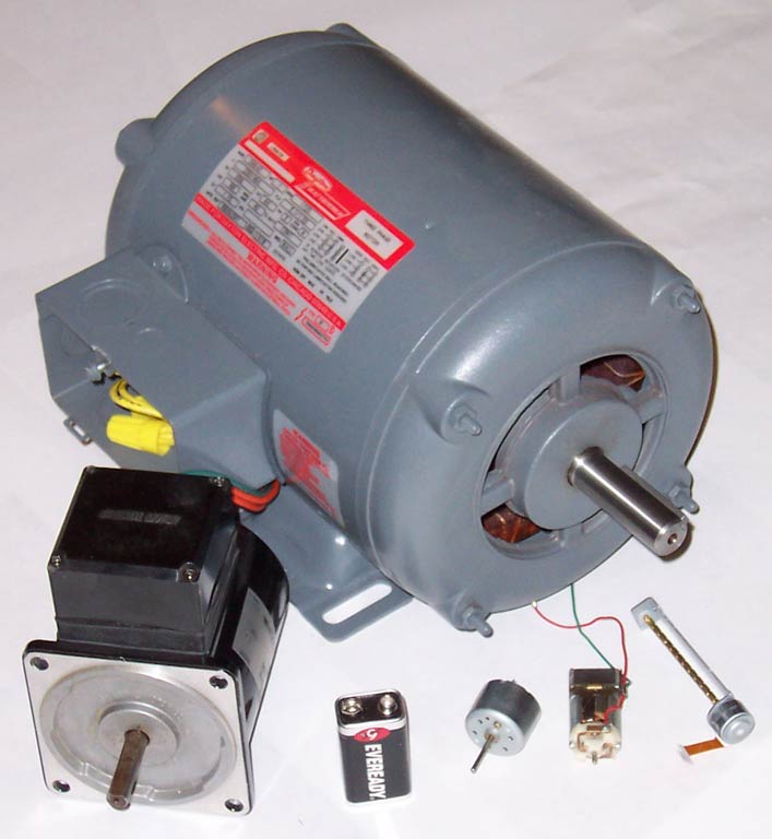
 Various electric motors. A 9-volt PP3 transistor battery is in the center foreground for size comparison.
An electric motor converts electrical energy into mechanical energy.
Most electric motors operate through the interaction of magnetic fields and current-carrying conductors to generate force. The reverse process, producing electrical energy from mechanical energy, is done by generators such as an alternator or a dynamo; some electric motors can also be used as generators, for example, a traction motor on a vehicle may perform both tasks. Electric motors and generators are commonly referred to as electric machines.
Electric motors are found in applications as diverse as industrial fans, blowers and pumps, machine tools, household appliances, power tools, and disk drives. They may be powered by direct current, e.g., a battery powered portable device or motor vehicle, or by alternating current from a central electrical distribution grid or inverter. The smallest motors may be found in electric wristwatches. Medium-size motors of highly standardized dimensions and characteristics provide convenient mechanical power for industrial uses. The very largest electric motors are used for propulsion of ships, pipeline compressors, and water pumps with ratings in the millions of watts. Electric motors may be classified by the source of electric power, by their internal construction, by their application, or by the type of motion they give.
The physical principle of production of mechanical force by the interactions of an electric current and a magnetic field was known as early as 1821. Electric motors of increasing efficiency were constructed throughout the 19th century, but commercial exploitation of electric motors on a large scale required efficient electrical generators and electrical distribution networks.
Some devices convert electricity into motion but do not generate usable mechanical power as a primary objective and so are not generally referred to as electric motors. For example, magnetic solenoids and loudspeakers are usually described as actuators and transducers,[1] respectively, instead of motors. Some electric motors are used to produce torque or force.[2]
Contents
- 1 History and development
- 2 Terminology
- 3 Operating principle
- 4 Use and styles
- 5 Performance
- 6 Motor standards
- 7 References and further reading
- 8 See also
- 9 External links
History and development
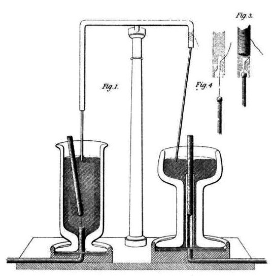
 Faraday's electromagnetic experiment, 1821[3]
The conversion of electrical energy into mechanical energy by electromagnetic means was demonstrated by the British scientist Michael Faraday in 1821. A free-hanging wire was dipped into a pool of mercury, on which a permanent magnet was placed. When a current was passed through the wire, the wire rotated around the magnet, showing that the current gave rise to a close circular magnetic field around the wire.[4] This motor is often demonstrated in school physics classes, but brine (salt water) is sometimes used in place of the toxic mercury. This is the simplest form of a class of devices called homopolar motors. A later refinement is the Barlow's wheel. These were demonstration devices only, unsuited to practical applications due to their primitive construction.[citation needed]
In 1827, Hungarian physicist Ányos Jedlik started experimenting with devices he called "electromagnetic self-rotors". Although they were used only for instructional purposes, in 1828 Jedlik demonstrated the first device to contain the three main components of practical direct current motors: the stator, rotor and commutator. The device employed no permanent magnets, as the magnetic fields of both the stationary and revolving components were produced solely by the currents flowing through their windings.[6][7][8][9][10][11]
The first electric motors
The first commutator-type direct current electric motor capable of turning machinery was invented by the British scientist William Sturgeon in 1832.[12] Following Sturgeon's work, a commutator-type direct-current electric motor made with the intention of commercial use was built by Americans Emily and Thomas Davenport and patented in 1837. Their motors ran at up to 600 revolutions per minute, and powered machine tools and a printing press.[13] Due to the high cost of the zinc electrodes required by primary battery power, the motors were commercially unsuccessful and the Davenports went bankrupt. Several inventors followed Sturgeon in the development of DC motors but all encountered the same cost issues with primary battery power. No electricity distribution had been developed at the time. Like Sturgeon's motor, there was no practical commercial market for these motors.[citation needed]
In 1855 Jedlik built a device using similar principles to those used in his electromagnetic self-rotors that was capable of useful work.[6][8] He built a model electric motor-propelled vehicle that same year.[14]
The modern DC motor was invented by accident in 1873, when Zénobe Gramme connected the dynamo he had invented to a second similar unit, driving it as a motor. The Gramme machine was the first electric motor that was successful in the industry.[citation needed]
In 1886 Frank Julian Sprague invented the first practical DC motor, a non-sparking motor capable of constant speed under variable loads. Other Sprague electric inventions about this time greatly improved grid electric distribution (prior work done while employed by Thomas Edison), allowed power from electric motors to be returned to the electric grid, provided for electric distribution to trolleys via overhead wires and the trolley pole, and provided controls systems for electric operations. This allowed Sprague to use electric motors to invent the first electric trolley system in 1887–88 in Richmond VA, the electric elevator and control system in 1892, and the electric subway with independently powered centrally controlled cars, which was first installed in 1892 in Chicago by the South Side Elevated Railway where it became popularly known as the "L". Sprague's motor and related inventions led to an explosion of interest and use in electric motors for industry, while almost simultaneously another great inventor was developing its primary competitor, which would become much more widespread.
In 1888 Nikola Tesla invented the first practicable AC motor and with it the polyphase power transmission system. Tesla continued his work on the AC motor in the years to follow at the Westinghouse company.
The development of electric motors of acceptable efficiency was delayed for several decades by failure to recognize the extreme importance of a relatively small air gap between rotor and stator. Efficient designs have a comparatively small air gap.[15]
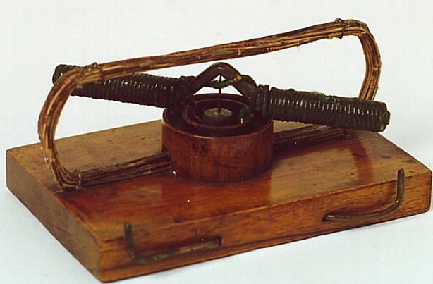
The St. Louis motor, long used in classrooms to illustrate motor principles, is extremely inefficient for the same reason, as well as appearing nothing like a modern motor. Photo of a traditional form of the St. Louis motor: [4]
Application of electric motors revolutionized industry. Industrial processes were no longer limited by power transmission using line shafts, belts, compressed air or hydraulic pressure. Instead every machine could be equipped with its own electric motor, providing easy control at the point of use, and improving power transmission efficiency. Electric motors applied in agriculture eliminated human and animal muscle power from such tasks as handling grain or pumping water. Household uses of electric motors reduced heavy labor in the home and made higher standards of convenience, comfort and safety possible. Today, electric motors consume more than half of all electric energy produced.[16][17]
Terminology
In an electric motor the moving part is called the rotor and the stationary part is called the stator. Magnetic fields are produced on poles, and these can be salient poles where they are driven by windings of electrical wire. A shaded pole contains an inductor to delay the phase of the magnetic field for that pole.
A commutator switches the current flow to the rotor windings depending on the rotor angle.
A DC motor is powered by direct current, although there is almost always an internal mechanism (such as a commutator) converting DC to AC for part of the motor. An AC motor is supplied with alternating current, often avoiding the need for a commutator. A synchronous motor is an AC motor that runs at a speed fixed to a fraction of the power supply frequency, and an asynchronous motor is an AC motor, usually an induction motor, whose speed slows with increasing torque to slightly less than synchronous speed. Universal motors can run on either AC or DC, though the maximum frequency of the AC supply may be limited.
Operating principle
At least 3 different operating principles are used to make electric motors: magnetism, electrostatics, piezoelectric. By far the most common is magnetic.
Magnetic
Nearly all electric motors are based around magnetism. In these motors, magnetic fields are formed in both the rotor and the stator. The product between these two fields give rise to a force, and thus a torque on the motor shaft. One, or both, of these fields must be made to change with the rotation of the motor. This is done by switching the poles on and off at the right time, or varying the strength of the pole.
Categorization
The main types are DC motors and AC motors, although the ongoing trend toward electronic control somewhat softens the distinction,[citation needed][dubious ] as modern drivers have moved the commutator out of the motor shell for some types of DC motors.
Considering all rotating (or linear) electric motors require synchronism between a moving magnetic field and a moving current sheet for average torque production, there is a clear distinction between an asynchronous motor and synchronous types. An asynchronous motor requires slip - relative movement between the magnetic field (generated by the stator) and a winding set (the rotor) to induce current in the rotor by mutual inductance. The most ubiquitous example of asynchronous motors is the common AC induction motor which must slip to generate torque.
In the synchronous types, induction (or slip) is not a requisite for magnetic field or current production (e.g. permanent magnet motors, synchronous brush-less wound-rotor doubly fed electric machine).
Rated output power is also used to categorize motors. Those of less than 746 watts, for example, are often referred to as fractional horsepower motors (FHP) in reference to the old imperial measurement.
Commutation No commutation Electromechanical Electronic stator coils driven by line voltage motor has a commutator to switch power to rotor coils Switches power to stator coils, rotor position by sensing, either by discrete sensors, or feedback from coils, or open loop. Electro-mechanical commutator Electronic switches Drive AC DC (1) DC Rotor Iron The rotor is ferromagnetic, not permanently magnetized; it has no winding RELUCTANCE (2):
• Hysteresis
• Synchronous reluctanceSwitched or variable reluctance / SRM Switched or variable reluctance / SRM
• Stepper
• Coilgun/mass driverMagnet The rotor is a permanent magnet; it has no winding PMSM / BLAC (2)
(Permanent Magnet Synchronous Motor / Brush-less Alternating Current)BLDC
(Brush-less Direct Current)Copper (usually plus magnetic core) The rotor includes a winding INDUCTION (3)
(Squirrel cage)PM
(Permanent Magnet)
WOUND STATOR:
• universal(1) / series wound
• shunt wound
• compound wound
Commutator supplies power to the coils that are best positioned to generate torque
Homopolar motor (ironless rotors typical)Frequency controlled induction motor fed from Inverter Notes:
- Universal motors can also work at line frequency AC (rotation is independent of the frequency of the AC voltage)
- Rotation is synchronous with the frequency of the AC voltage
- Rotation is always slower than synchronous.
DC motors
Main article: DC motorA DC motor is designed to run on DC electric power. Two examples of pure DC designs are Michael Faraday's homopolar motor (which is uncommon), and the ball bearing motor, which is (so far) a novelty. By far the most common DC motor types are the brushed and brushless types, which use internal and external commutation respectively to reverse the current in the windings in synchronism with rotation.
Permanent-magnet motors
Main article: Permanent-magnet electric motorA permanent-magnet motor does not have a field winding on the stator frame, instead relying on permanent magnets to provide the magnetic field against which the rotor field interacts to produce torque. Compensating windings in series with the armature may be used on large motors to improve commutation under load. Because this field is fixed, it cannot be adjusted for speed control. Permanent-magnet fields (stators) are convenient in miniature motors to eliminate the power consumption of the field winding. Most larger DC motors are of the "dynamo" type, which have stator windings. Historically, permanent magnets could not be made to retain high flux if they were disassembled; field windings were more practical to obtain the needed amount of flux. However, large permanent magnets are costly, as well as dangerous and difficult to assemble; this favors wound fields for large machines.
To minimize overall weight and size, miniature permanent-magnet motors may use high energy magnets made with neodymium or other strategic elements; most such are neodymium-iron-boron alloy. With their higher flux density, electric machines with high energy permanent magnets are at least competitive with all optimally designed singly fed synchronous and induction electric machines. Miniature motors resemble the structure in the illustration, except that they have at least three rotor poles (to ensure starting, regardless of rotor position) and their outer housing is a steel tube that magnetically links the exteriors of the curved field magnets.
Brushed DC motors
Main article: Brushed DC electric motor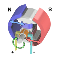 Workings of a brushed electric motor with a two-pole rotor and permanent-magnet stator. ("N" and "S" designate polarities on the inside faces of the magnets; the outside faces have opposite polarities.)
DC motors have AC in a wound rotor also called an armature, with a split ring commutator, and either a wound or permanent magnet stator. The commutator and brushes are a long-life rotary switch. The rotor consists of one or more coils of wire wound around a laminated "soft" ferromagnetic core on a shaft; an electrical power source feeds the rotor windings through the commutator and its brushes, temporarily magnetizing the rotor core in a specific direction. The commutator switches power to the coils as the rotor turns, keeping the magnetic poles of the rotor from ever fully aligning with the magnetic poles of the stator field, so that the rotor never stops (like a compass needle does), but rather keeps rotating as long as power is applied.
Many of the limitations of the classic commutator DC motor are due to the need for brushes to press against the commutator. This creates friction. Sparks are created by the brushes making and breaking circuits through the rotor coils as the brushes cross the insulating gaps between commutator sections. Depending on the commutator design, this may include the brushes shorting together adjacent sections – and hence coil ends – momentarily while crossing the gaps. Furthermore, the inductance of the rotor coils causes the voltage across each to rise when its circuit is opened, increasing the sparking of the brushes. This sparking limits the maximum speed of the machine, as too-rapid sparking will overheat, erode, or even melt the commutator. The current density per unit area of the brushes, in combination with their resistivity, limits the output of the motor. The making and breaking of electric contact also generates electrical noise; sparking generates RFI. Brushes eventually wear out and require replacement, and the commutator itself is subject to wear and maintenance (on larger motors) or replacement (on small motors). The commutator assembly on a large motor is a costly element, requiring precision assembly of many parts. On small motors, the commutator is usually permanently integrated into the rotor, so replacing it usually requires replacing the whole rotor.
While most commutators are cylindrical, some are flat discs consisting of several segments (typically, at least three) mounted on an insulator.
Large brushes are desired for a larger brush contact area to maximize motor output, but small brushes are desired for low mass to maximize the speed at which the motor can run without the brushes excessively bouncing and sparking (comparable to the problem of "valve float" in internal combustion engines). (Small brushes are also desirable for lower cost.) Stiffer brush springs can also be used to make brushes of a given mass work at a higher speed, but at the cost of greater friction losses (lower efficiency) and accelerated brush and commutator wear. Therefore, DC motor brush design entails a trade-off between output power, speed, and efficiency/wear.
- Notes on terminology
- The first practical electric motors, used for street railways, were DC with commutators. Power was fed to the commutators (made of copper) by copper brushes, but the voltage difference between adjacent commutator bars, excellent conductivity of the copper brushes, and arcing created considerable damage after only a quite short period of operation. An electrical engineer realized that replacing the copper brushes with electrically resistive solid carbon blocks would provide much longer life. Although the term is no longer descriptive, the carbon blocks continue to be called "brushes" even to this day.
- Sculptors who work with clay need support structures called armatures to keep larger works from sagging due to gravity. Magnetic laminations, in a rotor with windings, similarly support insulated-copper-wire coils. By analogy, wound rotors came to be called "armatures".[citation needed]
- Commutators, at least among some people who work with them daily, have become so familiar that some fail to realize that they are just a particular variety of rotary electrical switch. Considering how frequently connections make and break, they have very long lifetimes.
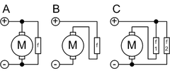 A: shuntB: seriesC: compoundf = field coil
There are five types of brushed DC motor:
- DC shunt-wound motor
- DC series-wound motor
- DC compound motor (two configurations):
- Cumulative compound
- Differentially compounded
- Permanent magnet DC motor (not shown)
- Separately excited (not shown)
Brushless DC motors
Main article: Brushless DC electric motorSome of the problems of the brushed DC motor are eliminated in the brushless design. In this motor, the mechanical "rotating switch" or commutator/brushgear assembly is replaced by an external electronic switch synchronised to the rotor's position. Brushless motors are typically 85–90% efficient or more, efficiency for a brushless electric motor, of up to 96.5% was reported[18] whereas DC motors with brushgear are typically 75–80% efficient.
Midway between ordinary DC motors and stepper motors lies the realm of the brushless DC motor. Built in a fashion very similar to stepper motors, these often use a permanent magnet external rotor, three phases of driving coils, may use Hall effect sensors to sense the position of the rotor, and associated drive electronics. The coils are activated, one phase after the other, by the drive electronics as cued by the signals from either Hall effect sensors or from the back EMF (electromotive force) of the undriven coils. In effect, they act as three-phase synchronous motors containing their own variable-frequency drive electronics. A specialized class of brushless DC motor controllers utilize EMF feedback through the main phase connections instead of Hall effect sensors to determine position and velocity. These motors are used extensively in electric radio-controlled vehicles. When configured with the magnets on the outside, these are referred to by modelers as outrunner motors.
Brushless DC motors are commonly used where precise speed control is necessary, as in computer disk drives or in video cassette recorders, the spindles within CD, CD-ROM (etc.) drives, and mechanisms within office products such as fans, laser printers and photocopiers. They have several advantages over conventional motors:
- Compared to AC fans using shaded-pole motors, they are very efficient, running much cooler than the equivalent AC motors. This cool operation leads to much-improved life of the fan's bearings.
- Without a commutator to wear out, the life of a DC brushless motor can be significantly longer compared to a DC motor using brushes and a commutator. Commutation also tends to cause a great deal of electrical and RF noise; without a commutator or brushes, a brushless motor may be used in electrically sensitive devices like audio equipment or computers.
- The same Hall effect sensors that provide the commutation can also provide a convenient tachometer signal for closed-loop control (servo-controlled) applications. In fans, the tachometer signal can be used to derive a "fan OK" signal as well as provide running speed feedback.
- The motor can be easily synchronized to an internal or external clock, leading to precise speed control.
- Brushless motors have no chance of sparking, unlike brushed motors, making them better suited to environments with volatile chemicals and fuels. Also, sparking generates ozone which can accumulate in poorly ventilated buildings risking harm to occupants' health.
- Brushless motors are usually used in small equipment such as computers and are generally used in fans to get rid of unwanted heat.
- They are also acoustically very quiet motors which is an advantage if being used in equipment that is affected by vibrations.
Modern DC brushless motors range in power from a fraction of a watt to many kilowatts. Larger brushless motors up to about 100 kW rating are used in electric vehicles. They also find significant use in high-performance electric model aircraft.
Switched reluctance motors
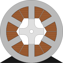 6/4 Pole Switched reluctance motorMain article: Switched reluctance motor
The switched reluctance motor (SRM) has no brushes or permanent magnets, and the rotor has no electric currents. Instead, torque comes from a slight mis-alignment of poles on the rotor with poles on the stator. The rotor aligns itself with the magnetic field of the stator, while the stator field stator windings are sequentially energized to rotate the stator field.
The magnetic flux created by the field windings follows the path of least magnetic reluctance, meaning the flux will flow through poles of the rotor that are closest to the energized poles of the stator, thereby magnitizing those poles of the rotor and creating torque. As the rotor turns, different windings will be energized, keeping the rotor turning.
Switched reluctance motors are now being used in some appliances.[19].
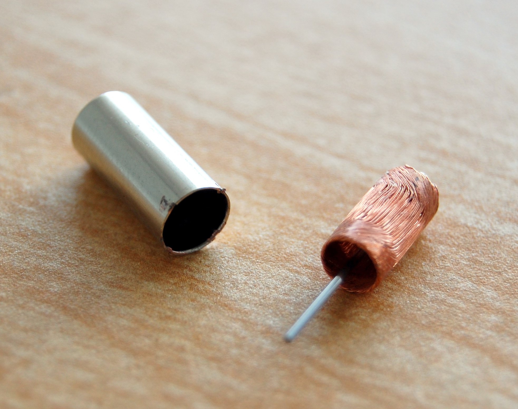
Coreless or ironless DC motors
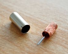 A Miniature Coreless Motor
Nothing in the principle of any of the motors described above requires that the iron (steel) portions of the rotor actually rotate. If the soft magnetic material of the rotor is made in the form of a cylinder, then (except for the effect of hysteresis) torque is exerted only on the windings of the electromagnets. Taking advantage of this fact is the coreless or ironless DC motor, a specialized form of a brush or brushless DC motor. Optimized for rapid acceleration, these motors have a rotor that is constructed without any iron core. The rotor can take the form of a winding-filled cylinder, or a self-supporting structure comprising only the magnet wire and the bonding material. The rotor can fit inside the stator magnets; a magnetically soft stationary cylinder inside the rotor provides a return path for the stator magnetic flux. A second arrangement has the rotor winding basket surrounding the stator magnets. In that design, the rotor fits inside a magnetically soft cylinder that can serve as the housing for the motor, and likewise provides a return path for the flux.
Because the rotor is much lighter in weight (mass) than a conventional rotor formed from copper windings on steel laminations, the rotor can accelerate much more rapidly, often achieving a mechanical time constant under 1 ms. This is especially true if the windings use aluminum rather than the heavier copper. But because there is no metal mass in the rotor to act as a heat sink, even small coreless motors must often be cooled by forced air. Overheating might be an issue for coreless DC motor designs.
Among these types are the disc-rotor types, described in more detail in the next section.
Vibrator motors for cellular phones are sometimes tiny cylindrical permanent-magnet field types, but there are also disc-shaped types which have a thin multipolar disc field magnet, and an intentionally unbalanced molded-plastic rotor structure with two bonded coreless coils. Metal brushes and a flat commutator switch power to the rotor coils.
Related limited-travel actuators have no core and a bonded coil placed between the poles of high-flux thin permanent magnets. These are the fast head positioners for rigid-disk ("hard disk") drives. Although the contemporary design differs considerably from that of loudspeakers, it is still loosely (and incorrectly) referred to as a "voice coil" structure, because some earlier rigid-disk-drive heads moved in straight lines, and had a drive structure much like that of a loudspeaker.
Printed armature or pancake DC motors
Main article: pancake (slot car)A rather unusual motor design, the printed armature or pancake motor has the windings shaped as a disc running between arrays of high-flux magnets. The magnets are arranged in a circle facing the rotor with space in between to form an axial air gap. This design is commonly known as the pancake motor because of its extremely flat profile, although the technology has had many brand names since its inception, such as ServoDisc.
The printed armature (originally formed on a printed circuit board) in a printed armature motor is made from punched copper sheets that are laminated together using advanced composites to form a thin rigid disc. The printed armature has a unique construction in the brushed motor world in that it does not have a separate ring commutator. The brushes run directly on the armature surface making the whole design very compact.
An alternative manufacturing method is to use wound copper wire laid flat with a central conventional commutator, in a flower and petal shape. The windings are typically stabilized by being impregnated with electrical epoxy potting systems. These are filled epoxies that have moderate mixed viscosity and a long gel time. They are highlighted by low shrinkage and low exotherm, and are typically UL 1446 recognized as a potting compound for use up to 180°C (Class H) (UL File No. E 210549).
The unique advantage of ironless DC motors is that there is no cogging (torque variations caused by changing attraction between the iron and the magnets). Parasitic eddy currents cannot form in the rotor as it is totally ironless, although iron rotors are laminated. This can greatly improve efficiency, but variable-speed controllers must use a higher switching rate (>40 kHz) or direct current because of the decreased electromagnetic induction.
These motors were originally invented to drive the capstan(s) of magnetic tape drives in the burgeoning computer industry, where minimal time to reach operating speed and minimal stopping distance were critical. Pancake motors are still widely used in high-performance servo-controlled systems, humanoid robotic systems, industrial automation and medical devices. Due to the variety of constructions now available, the technology is used in applications from high temperature military to low cost pump and basic servos.
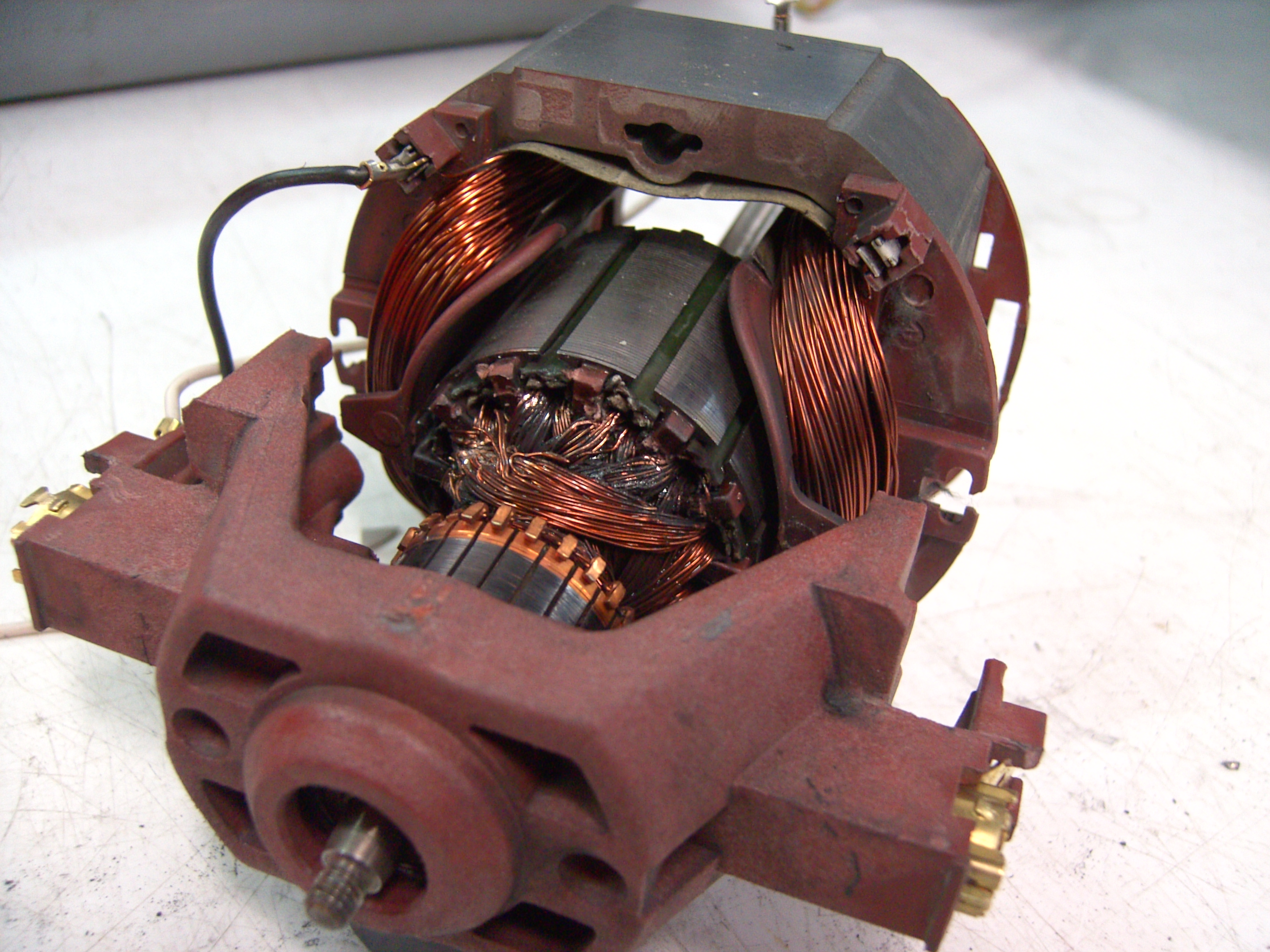
Universal motors
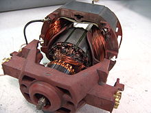 Modern low-cost universal motor, from a vacuum cleaner. Field windings are dark copper colored, toward the back, on both sides. The rotor's laminated core is gray metallic, with dark slots for winding the coils. The commutator (partly hidden) has become dark from use; it's toward the front. The large brown molded-plastic piece in the foreground supports the brush guides and brushes (both sides), as well as the front motor bearing.
A series-wound motor is referred to as a universal motor when it has been designed to operate on either AC or DC power. It can operate well on AC because the current in both the field and the armature (and hence the resultant magnetic fields) will alternate (reverse polarity) in synchronism, and hence the resulting mechanical force will occur in a constant direction of rotation.
Operating at normal power line frequencies, universal motors are often found in a range rarely larger than 1000 watt. Universal motors also form the basis of the traditional railway traction motor in electric railways. In this application, the use of AC to power a motor originally designed to run on DC would lead to efficiency losses due to eddy current heating of their magnetic components, particularly the motor field pole-pieces that, for DC, would have used solid (un-laminated) iron. Although the heating effects are reduced by using laminated pole-pieces, as used for the cores of transformers and by the use of laminations of high permeability electrical steel, one solution available at start of the 20th century was for the motors to be operated from very low frequency AC supplies, with 25 and 16.7 Hz operation being common. Because they used universal motors, locomotives using this design were also commonly capable of operating from a third rail or overhead wire powered by DC. As well, considering that steam engines directly powered many alternators, their relatively low speeds favored low frequencies because comparatively few stator poles were needed.
An advantage of the universal motor is that AC supplies may be used on motors which have some characteristics more common in DC motors, specifically high starting torque and very compact design if high running speeds are used. The negative aspect is the maintenance and short life problems caused by the commutator. Such motors are used in devices such as food mixers and power tools which are used only intermittently, and often have high starting-torque demands. Continuous speed control of a universal motor running on AC is easily obtained by use of a thyristor circuit, while multiple taps on the field coil provide (imprecise) stepped speed control. Household blenders that advertise many speeds frequently combine a field coil with several taps and a diode that can be inserted in series with the motor (causing the motor to run on half-wave rectified AC).
In the past, repulsion-start wound-rotor motors provided high starting torque, but with added complexity. Their rotors were similar to those of universal motors, but their brushes were connected only to each other. Transformer action induced current into the rotor. Brush position relative to field poles meant that starting torque was developed by rotor repulsion from the field poles. A centrifugal mechanism, when close to running speed, connected all commutator bars together to create the equivalent of a squirrel-cage rotor. As well, when close to operating speed, better motors lifted the brushes out of contact.
Induction motors cannot turn a shaft faster than allowed by the power line frequency. By contrast, universal motors generally run at high speeds, making them useful for appliances such as blenders, vacuum cleaners, and hair dryers where high speed and light weight is desirable. They are also commonly used in portable power tools, such as drills, sanders, circular and jig saws, where the motor's characteristics work well. Many vacuum cleaner and weed trimmer motors exceed 10,000 RPM, while Dremel and other similar miniature grinders will often exceed 30,000 RPM.
Universal motors also lend themselves to electronic speed control and, as such, are an ideal choice for domestic washing machines. The motor can be used to agitate the drum (both forwards and in reverse) by switching the field winding with respect to the armature. The motor can also be run up to the high speeds required for the spin cycle.
Motor damage may occur from overspeeding (running at a rotational speed in excess of design limits) if the unit is operated with no significant load. On larger motors, sudden loss of load is to be avoided, and the possibility of such an occurrence is incorporated into the motor's protection and control schemes. In some smaller applications, a fan blade attached to the shaft often acts as an artificial load to limit the motor speed to a safe level, as well as a means to circulate cooling airflow over the armature and field windings.
AC motors
Main article: AC motorIn 1882, Nikola Tesla discovered the rotating magnetic field, and pioneered the use of a rotary field of force to operate machines. He exploited the principle to design a unique two-phase induction motor in 1883. In 1885, Galileo Ferraris independently researched the concept. In 1888, Ferraris published his research in a paper to the Royal Academy of Sciences in Turin.
Tesla had suggested that the commutators from a machine could be removed and the device could operate on a rotary field of force. Professor Poeschel, his teacher, stated that would be akin to building a perpetual motion machine.[20] Tesla would later attain U.S. Patent 0,416,194, Electric Motor (December 1889), which resembles the motor seen in many of Tesla's photos. This classic alternating current electro-magnetic motor was an induction motor.
Michail Osipovich Dolivo-Dobrovolsky later invented a three-phase "cage-rotor" in 1890. This type of motor is now used for the vast majority of commercial applications.
An AC motor has two parts: a stationary stator having coils supplied with alternating current to produce a rotating magnetic field, and a rotor attached to the output shaft that is given a torque by the rotating field.
AC motor with sliding rotor
A conical-rotor brake motor incorporates the brake as an integral part of the conical sliding rotor. When the motor is at rest, a spring acts on the sliding rotor and forces the brake ring against the brake cap in the motor, holding the rotor stationary. When the motor is energized, its magnetic field generates both an axial and a radial component. The axial component overcomes the spring force, releasing the brake; while the radial component causes the rotor to turn. There is no additional brake control required.
Synchronous electric motor
Main article: Synchronous motorA synchronous electric motor is an AC motor distinguished by a rotor spinning with coils passing magnets at the same rate as the alternating current and resulting magnetic field which drives it. Another way of saying this is that it has zero slip under usual operating conditions. Contrast this with an induction motor, which must slip to produce torque. One type of synchronous motor is like an induction motor except the rotor is excited by a DC field. Slip rings and brushes are used to conduct current to the rotor. The rotor poles connect to each other and move at the same speed hence the name synchronous motor. Another type, for low load torque, has flats ground onto a conventional squirrel-cage rotor to create discrete poles. Yet another, such as made by Hammond for its pre-World War II clocks, and in the older Hammond organs, has no rotor windings and discrete poles. It is not self-starting. The clock requires manual starting by a small knob on the back, while the older Hammond organs had an auxiliary starting motor connected by a spring-loaded manually operated switch.
Finally, hysteresis synchronous motors typically are (essentially) two-phase motors with a phase-shifting capacitor for one phase. They start like induction motors, but when slip rate decreases sufficiently, the rotor (a smooth cylinder) becomes temporarily magnetized. Its distributed poles make it act like a permanent-magnet-rotor synchronous motor. The rotor material, like that of a common nail, will stay magnetized, but can also be demagnetized with little difficulty. Once running, the rotor poles stay in place; they do not drift.
Low-power synchronous timing motors (such as those for traditional electric clocks) may have multi-pole permanent-magnet external cup rotors, and use shading coils to provide starting torque. Telechron™ clock motors have shaded poles for starting torque, and a two-spoke ring rotor that performs like a discrete two-pole rotor.
Induction motor
Main article: Induction motorAn induction motor is an asynchronous AC motor where power is transferred to the rotor by electromagnetic induction, much like transformer action. An induction motor resembles a rotating transformer, because the stator (stationary part) is essentially the primary side of the transformer and the rotor (rotating part) is the secondary side. Polyphase induction motors are widely used in industry.
Induction motors may be further divided into squirrel-cage motors and wound-rotor motors. Squirrel-cage motors have a heavy winding made up of solid bars, usually aluminum or copper, joined by rings at the ends of the rotor. When one considers only the bars and rings as a whole, they are much like an animal's rotating exercise cage, hence the name.
Currents induced into this winding provide the rotor magnetic field. The shape of the rotor bars determines the speed-torque characteristics. At low speeds, the current induced in the squirrel cage is nearly at line frequency and tends to be in the outer parts of the rotor cage. As the motor accelerates, the slip frequency becomes lower, and more current is in the interior of the winding. By shaping the bars to change the resistance of the winding portions in the interior and outer parts of the cage, effectively a variable resistance is inserted in the rotor circuit. However, the majority of such motors have uniform bars.
In a wound-rotor motor, the rotor winding is made of many turns of insulated wire and is connected to slip rings on the motor shaft. An external resistor or other control devices can be connected in the rotor circuit. Resistors allow control of the motor speed, although significant power is dissipated in the external resistance. A converter can be fed from the rotor circuit and return the slip-frequency power that would otherwise be wasted back into the power system through an inverter or separate motor-generator.
The wound-rotor induction motor is used primarily to start a high inertia load or a load that requires a very high starting torque across the full speed range. By correctly selecting the resistors used in the secondary resistance or slip ring starter, the motor is able to produce maximum torque at a relatively low supply current from zero speed to full speed. This type of motor also offers controllable speed.
Motor speed can be changed because the torque curve of the motor is effectively modified by the amount of resistance connected to the rotor circuit. Increasing the value of resistance will move the speed of maximum torque down. If the resistance connected to the rotor is increased beyond the point where the maximum torque occurs at zero speed, the torque will be further reduced.
When used with a load that has a torque curve that increases with speed, the motor will operate at the speed where the torque developed by the motor is equal to the load torque. Reducing the load will cause the motor to speed up, and increasing the load will cause the motor to slow down until the load and motor torque are equal. Operated in this manner, the slip losses are dissipated in the secondary resistors and can be very significant. The speed regulation and net efficiency is also very poor.
Doubly fed electric motor
Main article: Doubly fed electric machineDoubly fed electric motors have two independent multiphase winding sets, which contribute active (i.e., working) power to the energy conversion process, with at least one of the winding sets electronically controlled for variable speed operation. Two independent multiphase winding sets (i.e., dual armature) are the maximum provided in a single package without topology duplication. Doubly fed electric motors are machines with an effective constant torque speed range that is twice synchronous speed for a given frequency of excitation. This is twice the constant torque speed range as singly fed electric machines, which have only one active winding set.
A doubly fed motor allows for a smaller electronic converter but the cost of the rotor winding and slip rings may offset the saving in the power electronics components. Difficulties with controlling speed near synchronous speed limit applications.[21]
Singly fed electric motor
Main article: Singly fed electric machineMost AC motors are singly fed. Singly fed electric motors have a single multiphase winding set that is connected to a power supply. Singly fed electric machines may be either induction or synchronous. The active winding set can be electronically controlled. Singly fed electric machines have an effective constant torque speed range up to synchronous speed for a given excitation frequency.
Torque motors
A torque motor (also known as a limited torque motor) is a specialized form of induction motor which is capable of operating indefinitely while stalled, that is, with the rotor blocked from turning, without incurring damage. In this mode of operation, the motor will apply a steady torque to the load (hence the name).
A common application of a torque motor would be the supply- and take-up reel motors in a tape drive. In this application, driven from a low voltage, the characteristics of these motors allow a relatively constant light tension to be applied to the tape whether or not the capstan is feeding tape past the tape heads. Driven from a higher voltage, (and so delivering a higher torque), the torque motors can also achieve fast-forward and rewind operation without requiring any additional mechanics such as gears or clutches. In the computer gaming world, torque motors are used in force feedback steering wheels.
Another common application is the control of the throttle of an internal combustion engine in conjunction with an electronic governor. In this usage, the motor works against a return spring to move the throttle in accordance with the output of the governor. The latter monitors engine speed by counting electrical pulses from the ignition system or from a magnetic pickup[22] and, depending on the speed, makes small adjustments to the amount of current applied to the motor. If the engine starts to slow down relative to the desired speed, the current will be increased, the motor will develop more torque, pulling against the return spring and opening the throttle. Should the engine run too fast, the governor will reduce the current being applied to the motor, causing the return spring to pull back and close the throttle.
Stepper motors
Main article: Stepper motorClosely related in design to three-phase AC synchronous motors are stepper motors, where an internal rotor containing permanent magnets or a magnetically soft rotor with salient poles is controlled by a set of external magnets that are switched electronically. A stepper motor may also be thought of as a cross between a DC electric motor and a rotary solenoid. As each coil is energized in turn, the rotor aligns itself with the magnetic field produced by the energized field winding. Unlike a synchronous motor, in its application, the stepper motor may not rotate continuously; instead, it "steps"—starts and then quickly stops again—from one position to the next as field windings are energized and de-energized in sequence. Depending on the sequence, the rotor may turn forwards or backwards, and it may change direction, stop, speed up or slow down arbitrarily at any time.
Simple stepper motor drivers entirely energize or entirely de-energize the field windings, leading the rotor to "cog" to a limited number of positions; more sophisticated drivers can proportionally control the power to the field windings, allowing the rotors to position between the cog points and thereby rotate extremely smoothly. This mode of operation is often called microstepping. Computer controlled stepper motors are one of the most versatile forms of positioning systems, particularly when part of a digital servo-controlled system.
Stepper motors can be rotated to a specific angle in discrete steps with ease, and hence stepper motors are used for read/write head positioning in computer floppy diskette drives. They were used for the same purpose in pre-gigabyte era computer disk drives, where the precision and speed they offered was adequate for the correct positioning of the read/write head of a hard disk drive. As drive density increased, the precision and speed limitations of stepper motors made them obsolete for hard drives—the precision limitation made them unusable, and the speed limitation made them uncompetitive—thus newer hard disk drives use voice coil-based head actuator systems. (The term "voice coil" in this connection is historic; it refers to the structure in a typical (cone type) loudspeaker. This structure was used for a while to position the heads. Modern drives have a pivoted coil mount; the coil swings back and forth, something like a blade of a rotating fan. Nevertheless, like a voice coil, modern actuator coil conductors (the magnet wire) move perpendicular to the magnetic lines of force.)
Stepper motors were and still are often used in computer printers, optical scanners, and digital photocopiers to move the optical scanning element, the print head carriage (of dot matrix and inkjet printers), and the platen or feed rollers. Likewise, many computer plotters (which since the early 1990s have been replaced with large-format inkjet and laser printers) used rotary stepper motors for pen and platen movement; the typical alternatives here were either linear stepper motors or servomotors with closed-loop analog control systems.
So-called quartz analog wristwatches contain the smallest commonplace stepping motors; they have one coil, draw very little power, and have a permanent-magnet rotor. The same kind of motor drives battery-powered quartz clocks. Some of these watches, such as chronographs, contain more than one stepping motor.
Stepper motors were upscaled to be used in electric vehicles under the term SRM (Switched Reluctance Motor).
Comparison
Comparison of motor types[23] Type Advantages Disadvantages Typical Application Typical Drive AC polyphase induction squirrel-cage Low cost, long life,
high efficiency,
large ratings available (to 1 MW or more),
large number of standardized typesStarting inrush current can be high,
speed control requires variable frequency sourcePumps, fans, blowers, conveyors, compressors Poly-phase AC, variable frequency AC Shaded-pole motor Low cost
Long lifeSpeed slightly below synchronous
Low starting torque
Small ratings
low efficiencyFans, appliances, record players Single phase AC AC induction – Squirrel cage, split-phase capacitor-start High power
high starting torqueSpeed slightly below synchronous
Starting switch or relay requiredAppliances
Stationary Power ToolsSingle phase AC AC induction – Squirrel cage, split-phase capacitor-run Moderate power
High starting torque
No starting switch
Comparatively long lifeSpeed slightly below synchronous
Slightly more costlyIndustrial blowers
Industrial machinerySingle phase AC AC induction – Squirrel cage motor, split-phase, auxiliary start winding Moderate power
Low starting torqueSpeed slightly below synchronous
Starting switch or relay requiredAppliances
Stationary Power ToolsSingle phase AC Universal motor High starting torque, compact, high speed. Maintenance (brushes)
Shorter lifespan
Usually acoustically noisy
Only small ratings are economicHandheld power tools, blenders, vacuum cleaners, insulation blowers Single phase AC or DC AC Synchronous Synchronous speed More costly Industrial motors
Clocks
Audio turntables
Tape drivesSingle or Polyphase AC (Capacitor-run for single-phase) Stepper DC Precision positioning
High holding torqueSome can be costly
Require a controllerPositioning in printers and floppy disc drives; industrial machine tools DC Brushless DC Long lifespan
Low maintenance
High efficiencyHigher initial cost
Requires a controllerRigid ("hard") disk drives
CD/DVD players
Electric vehicles
RC Vehicles
UAVsDC or PWM Switched reluctance motor Long lifespan
Low maintenance
High efficiency
No permanent magnets
Low cost
Simple constructionRequires a controller Appliances
Electric Vehicles
Textile mills
Aircraft applicationsDC or PWM Brushed DC Simple speed control Maintenance (brushes)
Medium lifespan
Costly commutator and brushesSteel mills
Paper making machines
Treadmill exercisers
Automotive accessoriesDirect DC or PWM Pancake DC Compact design
Simple speed controlMedium cost
Medium lifespanOffice Equip
Fans/Pumps, fast industrial and military servosDirect DC or PWM Goodness factor
Main article: Goodness factorProfessor Eric Laithwaite proposed a metric to determine the 'goodness' of an electric motor:[24]

Where:
- G is the goodness factor (factors above 1 are likely to be efficient)
- Am,Ae are the cross sections of the magnetic and electric circuit
- lm,le are the lengths of the magnetic and electric circuits
- μ is the permeability of the core
- ω is the angular frequency the motor is driven at
From this he showed that the most efficient motors are likely to have relatively large magnetic poles. However, the equation only directly relates to non permanent magnet motors.
Electrostatic
Main article: Electrostatic motorFull size
An electrostatic motor is based on the attraction and repulsion of electric charge. Usually, electrostatic motors are the dual of conventional coil-based motors. They typically require a high voltage power supply, although very small motors employ lower voltages. Conventional electric motors instead employ magnetic attraction and repulsion, and require high current at low voltages. In the 1750s, the first electrostatic motors were developed by Benjamin Franklin and Andrew Gordon. Today the electrostatic motor finds frequent use in micro-mechanical (MEMS) systems where their drive voltages are below 100 volts, and where moving, charged plates are far easier to fabricate than coils and iron cores. Also, the molecular machinery which runs living cells is often based on linear and rotary electrostatic motors.
Nanotube nanomotor
Main article: Nanotube nanomotorResearchers at University of California, Berkeley, recently developed rotational bearings based upon multiwall carbon nanotubes. By attaching a gold plate (with dimensions of the order of 100 nm) to the outer shell of a suspended multiwall carbon nanotube (like nested carbon cylinders), they are able to electrostatically rotate the outer shell relative to the inner core. These bearings are very robust; devices have been oscillated thousands of times with no indication of wear. These nanoelectromechanical systems (NEMS) are the next step in miniaturization and may find their way into commercial applications in the future.
See also:
- Molecular motors
- Nanomotor
- Electrostatic motor
Piezoelectric
Main article: Piezoelectric motorA piezoelectric motor or piezo motor is a type of electric motor based upon the change in shape of a piezoelectric material when an electric field is applied. Piezoelectric motors make use of the converse piezoelectric effect whereby the material produces acoustic or ultrasonic vibrations in order to produce a linear or rotary motion. In one mechanism, the elongation in a single plane is used to make a series stretches and position holds, similar to the way a caterpillar moves.
Use and styles
Standardized electric motors are often used in many modern machines but specific types of electric motors are designed for particular applications.
Rotary
Uses include rotating machines such as fans, turbines, drills, the wheels on electric cars, locomotives and conveyor belts. Also, in many vibrating or oscillating machines, an electric motor spins an unbalanced mass, causing the motor (and its mounting structure) to vibrate. A familiar application is cell phone vibrating alerts used when the acoustic "ringer" is disabled by the user.
Electric motors are also popular in robotics. They turn the wheels of vehicular robots, and servo motors operate arms in industrial robots; they also move arms and legs in humanoid robots. In flying robots, along with helicopters, a motor rotates a propeller, or aerodynamic rotor blades to create controllable amounts of lift.
Electric motors are replacing hydraulic cylinders in airplanes and military equipment.[25][26]
In industrial and manufacturing businesses, electric motors rotate saws and blades in cutting and slicing processes; they rotate parts being turned in lathes and other machine tools, and spin grinding wheels. Fast, precise servo motors position tools and work in modern CNC machine tools. Motor-driven mixers are very common in food manufacturing. Linear motors are often used to push products into containers horizontally.
Many kitchen appliances also use electric motors. Food processors and grinders spin blades to chop and break up foods. Blenders use electric motors to mix liquids, and microwave ovens use motors to turn the tray food that sits on. Toaster ovens also use electric motors to turn a conveyor to move food over heating elements.
Servo motor
Main article: Servo motorA servomotor is a motor, very often sold as a complete module, which is used within a position-control or speed-control feedback control system. Servomotors are used in applications such as machine tools, pen plotters, and other control systems. Motors intended for use in a servomechanism must have well-documented characteristics for speed, torque, and power. The speed vs. torque curve is quite important. Dynamic response characteristics such as winding inductance and rotor inertia are also important; these factors limit the overall performance of the servomechanism loop. Large, powerful, but slow-responding servo loops may use conventional AC or DC motors and drive systems with position or speed feedback on the motor. As dynamic response requirements increase, more specialized motor designs such as coreless motors are used.
A servo system differs from some stepper motor applications in that the position feedback is continuous while the motor is running; a stepper system relies on the motor not to "miss steps" for short term accuracy, although a stepper system may include a "home" switch or other element to provide long-term stability of control.[27] For instance, when an ink-jet computer printer starts up, its controller makes the print head stepper motor drive to its left-hand limit, where a position sensor defines home position and stops stepping. As long as power is on, a bidirectional counter in the printer's microprocessor keeps track of print-head position.
Linear motor
Main article: Linear motorA linear motor is essentially any electric motor that has been "unrolled" so that, instead of producing a torque (rotation), it produces a straight-line force along its length.
Linear motors are most commonly induction motors or stepper motors. Linear motors are commonly found in many roller-coasters where the rapid motion of the motorless railcar is controlled by the rail. They are also used in maglev trains, where the train "flies" over the ground. On a smaller scale, at least one letter-size (8.5" x 11") computer graphics X-Y pen plotter made by Hewlett-Packard (in the late 1970s to mid-1980s) used two linear stepper motors to move the pen along the two orthogonal axes.
Spacecraft propulsive motors
Main article: electrically powered spacecraft propulsionAn electrically powered spacecraft propulsion system is any of a number of forms of electric motors which spacecraft can employ to gain mechanical energy in outer space. Most of these kinds of spacecraft propulsion work by electrically powering propellant to high speed, but electrodynamic tethers work by interacting with a planet's magnetosphere.[28]
Generator
Main article: electrical generatorMany electric motors are used as generators, either part (such as regenerative braking) or all of their operational life. When mechanically driven magnetic electric motors produce power due to their back EMF.
Performance
Energy conversion by an electric motor
Using mathematical models in terms of a magnetic dipole, Ribarič and Šušteršič[29] consider how in the case of the synchronous motor and induction motor an external source is supplying electrical energy to the stator so as to maintain its revolving magnetic field; this energy is then transmitted by the revolving magnetic field to the magnetic dipole of the rotor; there it is converted into mechanical energy, and transmitted mechanically by the rotating shaft to an external user. On the other hand, in the case of a commutator motor, the external source delivers electrical energy directly to the rotor magnetic dipole for conversion into mechanical energy.
Power
The power output of a rotary electric motor is:
Where P is in horsepower, rpm is the shaft speed in revolutions per minute and T is the torque in foot pounds.
And for a linear motor:
Where P is the power in watts, and F is in Newtons and v is the speed in metres per second.
Efficiency
To calculate a motor's efficiency, the mechanical output power is divided by the electrical input power:
 , where η is energy conversion efficiency, Pe is electrical input power, and Pm is mechanical output power.
In simplest case Pe = VI, and Pm = Tω, where V is input voltage, I is input current, T is output torque, and ω is output angular velocity. It is possible to derive analytically the point of maximum efficiency. It is typically at less than 1/2 the stall torque.
Torque capability of motor types
When optimally designed within a given core saturation constraint and for a given active current (i.e., torque current), voltage, pole-pair number, excitation frequency (i.e., synchronous speed), and air-gap flux density, all categories of electric motors or generators will exhibit virtually the same maximum continuous shaft torque (i.e., operating torque) within a given air-gap area with winding slots and back-iron depth, which determines the physical size of electromagnetic core. Some applications require bursts of torque beyond the maximum operating torque, such as short bursts of torque to accelerate an electric vehicle from standstill. Always limited by magnetic core saturation or safe operating temperature rise and voltage, the capacity for torque bursts beyond the maximum operating torque differs significantly between categories of electric motors or generators.
Capacity for bursts of torque should not be confused with field weakening capability inherent in fully electromagnetic electric machines (Permanent Magnet (PM) electric machine are excluded). Field weakening, which is not available with PM electric machines, allows an electric machine to operate beyond the designed frequency of excitation.
Electric machines without a transformer circuit topology, such as Field-Wound (i.e., electromagnet) or Permanent Magnet (PM) Synchronous electric machines cannot realize bursts of torque higher than the maximum designed torque without saturating the magnetic core and rendering any increase in current as useless. Furthermore, the permanent magnet assembly of PM synchronous electric machines can be irreparably damaged, if bursts of torque exceeding the maximum operating torque rating are attempted.
Electric machines with a transformer circuit topology, such as Induction (i.e., asynchronous) electric machines, Induction Doubly Fed electric machines, and Induction or Synchronous Wound-Rotor Doubly Fed (WRDF) electric machines, exhibit very high bursts of torque because the active current (i.e., Magneto-Motive-Force or the product of current and winding-turns) induced on either side of the transformer oppose each other and as a result, the active current contributes nothing to the transformer coupled magnetic core flux density, which would otherwise lead to core saturation.
Electric machines that rely on Induction or Asynchronous principles short-circuit one port of the transformer circuit and as a result, the reactive impedance of the transformer circuit becomes dominant as slip increases, which limits the magnitude of active (i.e., real) current. Still, bursts of torque that are two to three times higher than the maximum design torque are realizable.
The Synchronous WRDF electric machine is the only electric machine with a truly dual ported transformer circuit topology (i.e., both ports independently excited with no short-circuited port). The dual ported transformer circuit topology is known to be unstable and requires a multiphase slip-ring-brush assembly to propagate limited power to the rotor winding set. If a precision means were available to instantaneously control torque angle and slip for synchronous operation during motoring or generating while simultaneously providing brushless power to the rotor winding set (see Brushless wound-rotor doubly fed electric machine), the active current of the Synchronous WRDF electric machine would be independent of the reactive impedance of the transformer circuit and bursts of torque significantly higher than the maximum operating torque and far beyond the practical capability of any other type of electric machine would be realizable. Torque bursts greater than eight times operating torque have been calculated.
Continuous Torque Density
The continuous torque density of conventional electric machines is determined by the size of the air-gap area and the back-iron depth, which are determined by the power rating of the armature winding set, the speed of the machine, and the achievable air-gap flux density before core saturation. Despite the high coercivity of neodymium or samarium-cobalt permanent magnets, continuous torque density is virtually the same amongst electric machines with optimally designed armature winding sets. Continuous torque density should never be confused with peak torque density, which comes with the manufacturer's chosen method of cooling, which is available to all, or period of operation before destruction by overheating of windings or even permanent magnet damage.
Continuous Power Density
The continuous power density is determined by the product of the continuous torque density and the constant torque speed range of the electric machine.
Motor standards
The following are major design and manufacturing standards covering electric motors:
- International Electrotechnical Commission: IEC 60034 Rotating Electrical Machines
- National Electrical Manufacturers Association (USA): NEMA MG 1 Motors and Generators
- Underwriters Laboratories (USA): UL 1004 - Standard for Electric Motors
References and further reading
- Citations
- ^ Schoenherr, Steven F. (2001), "Loudspeaker History". Recording Technology History. Retrieved 2010-03-13.
- ^ linear Electric Machines- A Personal View - Eric R. Laithwaite, Proceedings of the IEEE, Vol. 63, No. 2, February 1975 page 250
- ^ Faraday, Michael (1844). Experimental Researches in Electricity. 2. See plate 4.
- ^ spark museum
- ^ http://www.traveltohungary.com/english/articles/article.php?id=135
- ^ a b Electricity and magnetism, translated from the French of Amédée Guillemin. Rev. and ed. by Silvanus P. Thompson. London, MacMillan, 1891
- ^ Nature 53. (printed in 1896) page: 516
- ^ a b http://www.mpoweruk.com/timeline.htm
- ^ http://www.fh-zwickau.de/mbk/kfz_ee/praesentationen/Elma-Gndl-Generator%20-%20Druckversion.pdf
- ^ http://www.uni-regensburg.de/Fakultaeten/phil_Fak_I/Philosophie/Wissenschaftsgeschichte/Termine/E-Maschinen-Lexikon/Chronologie.htm
- ^ http://www.mpoweruk.com/history.htm
- ^ Gee, William (2004). "Sturgeon, William (1783–1850)". Oxford Dictionary of National Biography. Oxford, England: Oxford University Press. doi:10.1093/ref:odnb/26748.
- ^ [1] Garrison, Ervan G., "A history of engineering and technology". CRC Press, 1998. ISBN 0-8493-9810-X, 9780849398100. Retrieved May 7, 2009.
- ^ http://www.frankfurt.matav.hu/angol/magytud.htm
- ^ For a description and superb illustration of one such early electric motor designed by Froment, see a Google Books PDF online version of Ganot's Physics, 14th Edition, N.Y., 1893 translated by Atkinson, pp. 907 and 908. (Section 899, and Figure 888). [2]
- ^ http://www.switch-asia.eu/switch-projects/project-progress/projects-on-improving-production/efficient-electric-motor-system.html Electric motors use 60% of china's electric energy, for example
- ^ http://www1.eere.energy.gov/industry/bestpractices/pdfs/mc-0382.pdf US Department of Energy indicates over half US electricity generation is used by electric motors
- ^ Tokai University Unveils 100W DC Motor with 96% Efficiency http://techon.nikkeibp.co.jp/english/NEWS_EN/20090403/168295/
- ^ http://www.electronicsweekly.com/Articles/2010/08/13/46377/dyson-vacuums-104000rpm-brushless-dc-technology.htm
- ^ "Tesla's Early Years". PBS.
- ^ Cyril W. Lander, Power Electronics 3rd Edition, Mc Graw Hill International UK Limited, London 1993 ISBN 0-07-707714-8 Chapter 9–8 Slip Ring Induction Motor Control
- ^ http://www.daytronic.com/products/trans/t-magpickup.htm
- ^ http://www.circuitcellar.com/ Motor Comparison, Circuit Cellar Magazine, July 2008, Issue 216, Bachiochi, p.78 (Table edited in Wikipedia, May 2011)
- ^ The “Goodness” of Small Contemporary Permanent Magnet Electric Machines - D J Patterson, C W Brice, R A Dougal, D Kovuri
- ^ Briere D. and Traverse, P. (1993) “Airbus A320/A330/A340 Electrical Flight Controls: A Family of Fault-Tolerant Systems” Proc. FTCS, pp. 616–623.
- ^ North, David. (2000) "Finding Common Ground in Envelope Protection Systems". Aviation Week & Space Technology, Aug 28, pp. 66–68.
- ^ Patrick, Dale R; Fardo, Stephen W., Rotating Electrical Machines and Power Systems (2nd Edition)1997 Fairmont Press, Inc. ISBN 978-0-88173-239-9 chapter 11
- ^ [3]
- ^ [ Ribarič M. and Šušteršič L. Moving pointlike charges and electric and magnetic dipoles, AM.J.Phys.60(6),June 1992 ]
- General references
- Donald G. Fink and H. Wayne Beaty, Standard Handbook for Electrical Engineers, Eleventh Edition, McGraw-Hill, New York, 1978, ISBN 0-07-020974-X.
- Edwin J. Houston and Arthur Kennelly, Recent Types of Dynamo-Electric Machinery, copyright American Technical Book Company 1897, published by P.F. Collier and Sons New York, 1902
- Kuphaldt, Tony R. (2000–2006). "Chapter 13 AC MOTORS". Lessons In Electric Circuits—Volume II. http://www.ibiblio.org/obp/electricCircuits/AC/AC_13.html. Retrieved 2006-04-11.
- "A.O.Smith: The AC's and DC's of Electric Motors" (PDF). http://www.aosmithmotors.com/uploadedFiles/AC-DC%20manual.pdf. Retrieved 2009-12-07.
- Resenblat & Frienman DC and AC machinery
- http://www.streetdirectory.com/travel_guide/115541/technology/understanding_electric_motors_and_their_uses.html
- Further reading
- Shanefield D. J., Industrial Electronics for Engineers, Chemists, and Technicians,William Andrew Publishing, Norwich, NY, 2001.
- Fitzgerald/Kingsley/Kusko (Fitzgerald/Kingsley/Umans in later years), Electric Machinery, classic text for junior and senior electrical engineering students. Originally published in 1952, 6th edition published in 2002.
- Bedford, B. D.; Hoft, R. G. et al. (1964). Principles of Inverter Circuits. New York: John Wiley & Sons, Inc.. ISBN 0 471 06134 4. (Inverter circuits are used for variable-frequency motor speed control)
- B. R. Pelly, "Thyristor Phase-Controlled Converters and Cycloconverters: Operation, Control, and Performance" (New York: John Wiley, 1971).
- John N. Chiasson, Modeling and High Performance Control of Electric Machines, Wiley-IEEE Press, New York, 2005, ISBN 0-471-68449-X.
See also
Scientists and engineers:
- Charles Proteus Steinmetz
- Giuseppe Domenico Botto
- Miksa Déri
- Nikola Tesla
- Ottó Bláthy
Related subjects:
- Balancing machine
- Electrical engineering
- Electrically powered spacecraft propulsion
- Polyphase system
- Power factor
- Power-to-weight ratio
- Timeline of motor and engine technology
- Traction motor
Electric motors Broad motor categories 
Conventional
electric motorsUnusual electric motors Ball bearing • Homopolar • Piezoelectric • Ultrasonic • Electrostatic • Switched reluctance • Superconducting electric machine • Electrically powered spacecraft propulsionMotor
controllersSee also External links
- Electricity museum: early motors
- Electric Motors and Generators, explanations with animations from the University of New South Wales.
- The Numbers Game: A Primer on Single-Phase A.C. Electric Motor Horsepower Ratings, Kevin S. Brady.
- Theory of DC motor speed control
- International Energy Agency (IEA) 4E Annex concerned with Energy Efficiency in Electric Motor Systems
- Interactive Animation of a 3-Phase AC Electric Motor
- Kinematic Models for Design Digital Library (KMODDL) - Movies and photos of hundreds of working mechanical-systems models at Cornell University. Also includes an e-book library of classic texts on mechanical design and engineering.
- How Printed Motors work
- Interactive Java Animation: The Rotating Magnetic Field
- Asynchronous Motor: Explanation of operation
Categories:- Electric motors
- Electrical engineering
- Electromagnetic components
- Energy conversion
- Nikola Tesla
- British inventions
- Magnetic propulsion devices


![[4]](http://www.physics.umd.edu/lecdem/services/demos/demosk4/k4-21.gif)
Wikimedia Foundation. 2010.