- Gear
-
For the gear-like device used to drive a roller chain, see Sprocket.This article is about mechanical gears. For other uses, see Gear (disambiguation).
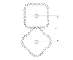
 Two meshing gears transmitting rotational motion. Note that the smaller gear is rotating faster. Although the larger gear is rotating less quickly, its torque is proportionally greater.
A gear is a rotating machine part having cut teeth, or cogs, which mesh with another toothed part in order to transmit torque. Two or more gears working in tandem are called a transmission and can produce a mechanical advantage through a gear ratio and thus may be considered a simple machine. Geared devices can change the speed, torque, and direction of a power source. The most common situation is for a gear to mesh with another gear, however a gear can also mesh a non-rotating toothed part, called a rack, thereby producing translation instead of rotation.
The gears in a transmission are analogous to the wheels in a pulley. An advantage of gears is that the teeth of a gear prevent slipping.
When two gears of unequal number of teeth are combined a mechanical advantage is produced, with both the rotational speeds and the torques of the two gears differing in a simple relationship.
In transmissions which offer multiple gear ratios, such as bicycles and cars, the term gear, as in first gear, refers to a gear ratio rather than an actual physical gear. The term is used to describe similar devices even when gear ratio is continuous rather than discrete, or when the device does not actually contain any gears, as in a continuously variable transmission.[1]
The earliest known reference to gears was circa A.D. 50 by Hero of Alexandria,[2] but they can be traced back to the Greek mechanics of the Alexandrian school in the 3rd century B.C. and were greatly developed by the Greek polymath Archimedes (287–212 B.C.).[3] The Antikythera mechanism is an example of a very early and intricate geared device, designed to calculate astronomical positions. Its time of construction is now estimated between 150 and 100 BC.[4]
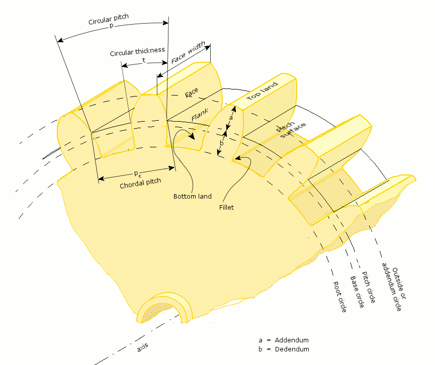
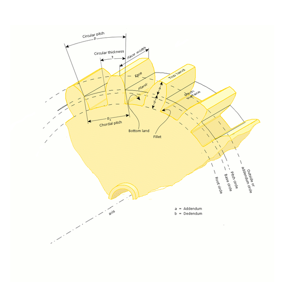 Definition of gear terminology.
Contents
Comparison with drive mechanisms
The definite velocity ratio which results from having teeth gives gears an advantage over other drives (such as traction drives and V-belts) in precision machines such as watches that depend upon an exact velocity ratio. In cases where driver and follower are in close proximity gears also have an advantage over other drives in the reduced number of parts required; the downside is that gears are more expensive to manufacture and their lubrication requirements may impose a higher operating cost.
The automobile transmission allows selection between gears to give various mechanical advantages.
Types
External vs internal gears
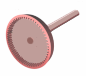 Internal gear
An external gear is one with the teeth formed on the outer surface of a cylinder or cone. Conversely, an internal gear is one with the teeth formed on the inner surface of a cylinder or cone. For bevel gears, an internal gear is one with the pitch angle exceeding 90 degrees. Internal gears do not cause direction reversal.[5]
Spur
 Spur gear
Spur gears or straight-cut gears are the simplest type of gear. They consist of a cylinder or disk with the teeth projecting radially, and although they are not straight-sided in form, the edge of each tooth is straight and aligned parallel to the axis of rotation. These gears can be meshed together correctly only if they are fitted to parallel shafts.
Helical
 Helical gears
Top: parallel configuration
Bottom: crossed configurationHelical or "dry fixed" gears offer a refinement over spur gears. The leading edges of the teeth are not parallel to the axis of rotation, but are set at an angle. Since the gear is curved, this angling causes the tooth shape to be a segment of a helix. Helical gears can be meshed in a parallel or crossed orientations. The former refers to when the shafts are parallel to each other; this is the most common orientation. In the latter, the shafts are non-parallel, and in this configuration are sometimes known as "skew gears".
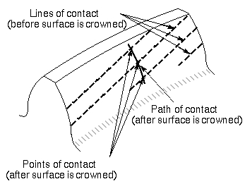
The angled teeth engage more gradually than do spur gear teeth causing them to run more smoothly and quietly.[6] With parallel helical gears, each pair of teeth first make contact at a single point at one side of the gear wheel; a moving curve of contact then grows gradually across the tooth face to a maximum then recedes until the teeth break contact at a single point on the opposite side. In spur gears teeth suddenly meet at a line contact across their entire width causing stress and noise. Spur gears make a characteristic whine at high speeds. Whereas spur gears are used for low speed applications and those situations where noise control is not a problem, the use of helical gears is indicated when the application involves high speeds, large power transmission, or where noise abatement is important. The speed is considered to be high when the pitch line velocity exceeds 25 m/s.[7]
A disadvantage of helical gears is a resultant thrust along the axis of the gear, which needs to be accommodated by appropriate thrust bearings, and a greater degree of sliding friction between the meshing teeth, often addressed with additives in the lubricant.
Skew gears
For a 'crossed' or 'skew' configuration the gears must have the same pressure angle and normal pitch, however the helix angle and handedness can be different. The relationship between the two shafts is actually defined by the helix angle(s) of the two shafts and the handedness, as defined:[8]
- E = β1 + β2 for gears of the same handedness
- E = β1 − β2 for gears of opposite handedness
Where β is the helix angle for the gear. The crossed configuration is less mechanically sound because there is only a point contact between the gears, whereas in the parallel configuration there is a line contact.[8]
Quite commonly helical gears are used with the helix angle of one having the negative of the helix angle of the other; such a pair might also be referred to as having a right-handed helix and a left-handed helix of equal angles. The two equal but opposite angles add to zero: the angle between shafts is zero – that is, the shafts are parallel. Where the sum or the difference (as described in the equations above) is not zero the shafts are crossed. For shafts crossed at right angles the helix angles are of the same hand because they must add to 90 degrees.
Double helical
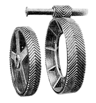
 Double helical gearsMain article: Double helical gear
Double helical gears, or herringbone gear, overcome the problem of axial thrust presented by "single" helical gears by having two sets of teeth that are set in a V shape. Each gear in a double helical gear can be thought of as two standard mirror image helical gears stacked. This cancels out the thrust since each half of the gear thrusts in the opposite direction. Double helical gears are more difficult to manufacture due to their more complicated shape.
For each possible direction of rotation, there are two possible arrangements of two oppositely-oriented helical gears or gear faces. In one possible orientation, the helical gear faces are oriented so that the axial force generated by each is in the axial direction away from the center of the gear; this arrangement is unstable. In the second possible orientation, which is stable, the helical gear faces are oriented so that each axial force is toward the mid-line of the gear. In both arrangements, when the gears are aligned correctly, the total (or net) axial force on each gear is zero. If the gears become misaligned in the axial direction, the unstable arrangement generates a net force for disassembly of the gear train, while the stable arrangement generates a net corrective force. If the direction of rotation is reversed, the direction of the axial thrusts is reversed, a stable configuration becomes unstable, and vice versa.
Stable double helical gears can be directly interchanged with spur gears without any need for different bearings.
Bevel
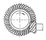
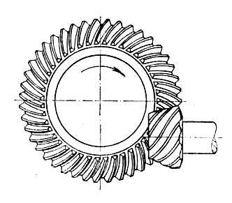
 Bevel gearMain article: Bevel gear
A bevel gear is shaped like a right circular cone with most of its tip cut off. When two bevel gears mesh, their imaginary vertices must occupy the same point. Their shaft axes also intersect at this point, forming an arbitrary non-straight angle between the shafts. The angle between the shafts can be anything except zero or 180 degrees. Bevel gears with equal numbers of teeth and shaft axes at 90 degrees are called miter gears.
The teeth of a bevel gear may be straight-cut as with spur gears, or they may be cut in a variety of other shapes. Spiral bevel gear teeth are curved along the tooth's length and set at an angle, analogously to the way helical gear teeth are set at an angle compared to spur gear teeth. Zerol bevel gears have teeth which are curved along their length, but not angled. Spiral bevel gears have the same advantages and disadvantages relative to their straight-cut cousins as helical gears do to spur gears. Straight bevel gears are generally used only at speeds below 5 m/s (1000 ft/min), or, for small gears, 1000 r.p.m.[9]
Hypoid
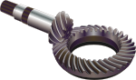
 Hypoid gearMain article: Spiral bevel gear
Hypoid gears resemble spiral bevel gears except the shaft axes do not intersect. The pitch surfaces appear conical but, to compensate for the offset shaft, are in fact hyperboloids of revolution.[10][11] Hypoid gears are almost always designed to operate with shafts at 90 degrees. Depending on which side the shaft is offset to, relative to the angling of the teeth, contact between hypoid gear teeth may be even smoother and more gradual than with spiral bevel gear teeth. Also, the pinion can be designed with fewer teeth than a spiral bevel pinion, with the result that gear ratios of 60:1 and higher are feasible using a single set of hypoid gears.[12] This style of gear is most commonly found driving mechanical differentials; which are normally straight cut bevel gears; in motor vehicle axles.
Crown
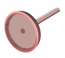
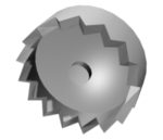 Crown gear
Crown gears or contrate gears are a particular form of bevel gear whose teeth project at right angles to the plane of the wheel; in their orientation the teeth resemble the points on a crown. A crown gear can only mesh accurately with another bevel gear, although crown gears are sometimes seen meshing with spur gears. A crown gear is also sometimes meshed with an escapement such as found in mechanical clocks.
Worm
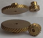
 Worm gear
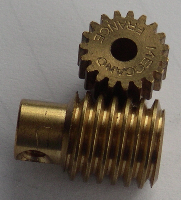
 4-start worm and wheelMain article: Worm driveMain article: Slewing drive
Worm gears resemble screws. A worm gear is usually meshed with a spur gear or a helical gear, which is called the gear, wheel, or worm wheel.
Worm-and-gear sets are a simple and compact way to achieve a high torque, low speed gear ratio. For example, helical gears are normally limited to gear ratios of less than 10:1 while worm-and-gear sets vary from 10:1 to 500:1.[13] A disadvantage is the potential for considerable sliding action, leading to low efficiency.[14]
Worm gears can be considered a species of helical gear, but its helix angle is usually somewhat large (close to 90 degrees) and its body is usually fairly long in the axial direction; and it is these attributes which give it screw like qualities. The distinction between a worm and a helical gear is made when at least one tooth persists for a full rotation around the helix. If this occurs, it is a 'worm'; if not, it is a 'helical gear'. A worm may have as few as one tooth. If that tooth persists for several turns around the helix, the worm will appear, superficially, to have more than one tooth, but what one in fact sees is the same tooth reappearing at intervals along the length of the worm. The usual screw nomenclature applies: a one-toothed worm is called single thread or single start; a worm with more than one tooth is called multiple thread or multiple start. The helix angle of a worm is not usually specified. Instead, the lead angle, which is equal to 90 degrees minus the helix angle, is given.
In a worm-and-gear set, the worm can always drive the gear. However, if the gear attempts to drive the worm, it may or may not succeed. Particularly if the lead angle is small, the gear's teeth may simply lock against the worm's teeth, because the force component circumferential to the worm is not sufficient to overcome friction. Worm-and-gear sets that do lock are called self locking, which can be used to advantage, as for instance when it is desired to set the position of a mechanism by turning the worm and then have the mechanism hold that position. An example is the machine head found on some types of stringed instruments.
If the gear in a worm-and-gear set is an ordinary helical gear only a single point of contact will be achieved.[15] If medium to high power transmission is desired, the tooth shape of the gear is modified to achieve more intimate contact by making both gears partially envelop each other. This is done by making both concave and joining them at a saddle point; this is called a cone-drive.[16]
Worm gears can be right or left-handed following the long established practice for screw threads.[5]
Non-circular
 Non-circular gearsMain article: Non-circular gear
Non-circular gears are designed for special purposes. While a regular gear is optimized to transmit torque to another engaged member with minimum noise and wear and maximum efficiency, a non-circular gear's main objective might be ratio variations, axle displacement oscillations and more. Common applications include textile machines, potentiometers and continuously variable transmissions.
Rack and pinion
 Rack and pinion gearingMain article: Rack and pinion
A rack is a toothed bar or rod that can be thought of as a sector gear with an infinitely large radius of curvature. Torque can be converted to linear force by meshing a rack with a pinion: the pinion turns; the rack moves in a straight line. Such a mechanism is used in automobiles to convert the rotation of the steering wheel into the left-to-right motion of the tie rod(s). Racks also feature in the theory of gear geometry, where, for instance, the tooth shape of an interchangeable set of gears may be specified for the rack (infinite radius), and the tooth shapes for gears of particular actual radii then derived from that. The rack and pinion gear type is employed in a rack railway.
Epicyclic
 Epicyclic gearingMain article: Epicyclic gearing
In epicyclic gearing one or more of the gear axes moves. Examples are sun and planet gearing (see below) and mechanical differentials.
Sun and planet
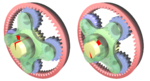
 Sun (yellow) and planet (red) gearingMain article: Sun and planet gear
Sun and planet gearing was a method of converting reciprocal motion into rotary motion in steam engines. It played an important role in the Industrial Revolution. The Sun is yellow, the planet red, the reciprocating crank is blue, the flywheel is green and the driveshaft is grey.
Harmonic drive
 Harmonic drive gearingMain article: Harmonic drive
A harmonic drive is a specialized gearing mechanism often used in industrial motion control, robotics and aerospace for its advantages over traditional gearing systems, including lack of backlash, compactness and high gear ratios.
Cage gear
 Cage gear in Pantigo Windmill, Long Island
A cage gear, also called a lantern gear or lantern pinion has cylindrical rods for teeth, parallel to the axle and arranged in a circle around it, much as the bars on a round bird cage or lantern. The assembly is held together by disks at either end into which the tooth rods and axle are set.
Nomenclature
Main article: Gear nomenclatureGeneral nomenclature
- Rotational frequency, n
- Measured in rotation over time, such as RPM.
- Angular frequency, ω
- Measured in radians per second. 1RPM = π / 30 rad/second
- Number of teeth, N
- How many teeth a gear has, an integer. In the case of worms, it is the number of thread starts that the worm has.
- Gear, wheel
- The larger of two interacting gears or a gear on its own.
- Pinion
- The smaller of two interacting gears.
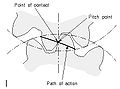
- Path of contact
- Path followed by the point of contact between two meshing gear teeth.
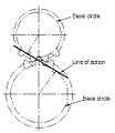
- Line of action, pressure line
- Line along which the force between two meshing gear teeth is directed. It has the same direction as the force vector. In general, the line of action changes from moment to moment during the period of engagement of a pair of teeth. For involute gears, however, the tooth-to-tooth force is always directed along the same line—that is, the line of action is constant. This implies that for involute gears the path of contact is also a straight line, coincident with the line of action—as is indeed the case.
- Axis
- Axis of revolution of the gear; center line of the shaft.
- Pitch point, p
- Point where the line of action crosses a line joining the two gear axes.
- Pitch circle, pitch line
- Circle centered on and perpendicular to the axis, and passing through the pitch point. A predefined diametral position on the gear where the circular tooth thickness, pressure angle and helix angles are defined.
- Pitch diameter, d
- A predefined diametral position on the gear where the circular tooth thickness, pressure angle and helix angles are defined. The standard pitch diameter is a basic dimension and cannot be measured, but is a location where other measurements are made. Its value is based on the number of teeth, the normal module (or normal diametral pitch), and the helix angle. It is calculated as:
 in metric units or
  in imperial units.[17]
- Module, m
- A scaling factor used in metric gears with units in millimeters whose effect is to enlarge the gear tooth size as the module increases and reduce the size as the module decreases. Module can be defined in the normal (mn), the transverse (mt), or the axial planes (ma) depending on the design approach employed and the type of gear being designed.[17] Module is typically an input value into the gear design and is seldom calculated.
- Operating pitch diameters
- Diameters determined from the number of teeth and the center distance at which gears operate.[5] Example for pinion:

- Pitch surface
- In cylindrical gears, cylinder formed by projecting a pitch circle in the axial direction. More generally, the surface formed by the sum of all the pitch circles as one moves along the axis. For bevel gears it is a cone.
- Angle of action
- Angle with vertex at the gear center, one leg on the point where mating teeth first make contact, the other leg on the point where they disengage.
- Arc of action
- Segment of a pitch circle subtended by the angle of action.
- Pressure angle, θ
- The complement of the angle between the direction that the teeth exert force on each other, and the line joining the centers of the two gears. For involute gears, the teeth always exert force along the line of action, which, for involute gears, is a straight line; and thus, for involute gears, the pressure angle is constant.
- Outside diameter, Do
- Diameter of the gear, measured from the tops of the teeth.
- Root diameter
- Diameter of the gear, measured at the base of the tooth.
- Addendum, a
- Radial distance from the pitch surface to the outermost point of the tooth. a = (Do − D) / 2
- Dedendum, b
- Radial distance from the depth of the tooth trough to the pitch surface. b = (D − rootdiameter) / 2
- Whole depth, ht
- The distance from the top of the tooth to the root; it is equal to addendum plus dedendum or to working depth plus clearance.
- Clearance
- Distance between the root circle of a gear and the addendum circle of its mate.
- Working depth
- Depth of engagement of two gears, that is, the sum of their operating addendums.
- Circular pitch, p
- Distance from one face of a tooth to the corresponding face of an adjacent tooth on the same gear, measured along the pitch circle.
- Diametral pitch, pd
- Ratio of the number of teeth to the pitch diameter. Could be measured in teeth per inch or teeth per centimeter.
- Base circle
- In involute gears, where the tooth profile is the involute of the base circle. The radius of the base circle is somewhat smaller than that of the pitch circle.
- Base pitch, normal pitch, pb
- In involute gears, distance from one face of a tooth to the corresponding face of an adjacent tooth on the same gear, measured along the base circle.
- Interference
- Contact between teeth other than at the intended parts of their surfaces.
- Interchangeable set
- A set of gears, any of which will mate properly with any other.
Helical gear nomenclature
- Helix angle, ψ
- Angle between a tangent to the helix and the gear axis. It is zero in the limiting case of a spur gear, albeit it can considered as the hypotenuse angle as well.
- Normal circular pitch, pn
- Circular pitch in the plane normal to the teeth.
- Transverse circular pitch, p
- Circular pitch in the plane of rotation of the gear. Sometimes just called "circular pitch". pn = pcos(ψ)
Several other helix parameters can be viewed either in the normal or transverse planes. The subscript n usually indicates the normal.
Worm gear nomenclature
- Lead
- Distance from any point on a thread to the corresponding point on the next turn of the same thread, measured parallel to the axis.
- Linear pitch, p
- Distance from any point on a thread to the corresponding point on the adjacent thread, measured parallel to the axis. For a single-thread worm, lead and linear pitch are the same.
- Lead angle, λ
- Angle between a tangent to the helix and a plane perpendicular to the axis. Note that it is the complement of the helix angle which is usually given for helical gears.
- Pitch diameter, dw
- Same as described earlier in this list. Note that for a worm it is still measured in a plane perpendicular to the gear axis, not a tilted plane.
Subscript w denotes the worm, subscript g denotes the gear.
Tooth contact nomenclature
-

Line of contact
-
Path of action
-
Line of action
-
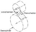
Plane of action
-
Lines of contact (helical gear)
-

Arc of action
-
Length of action
-

Limit diameter
-
Face advance
-
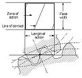
Zone of action
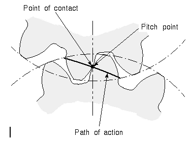
- Point of contact
- Any point at which two tooth profiles touch each other.
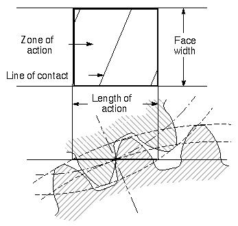
- Line of contact
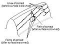
- A line or curve along which two tooth surfaces are tangent to each other.
- Path of action
- The locus of successive contact points between a pair of gear teeth, during the phase of engagement. For conjugate gear teeth, the path of action passes through the pitch point. It is the trace of the surface of action in the plane of rotation.
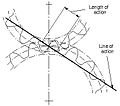
- Line of action
- The path of action for involute gears. It is the straight line passing through the pitch point and tangent to both base circles.
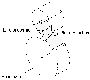
- Surface of action
- The imaginary surface in which contact occurs between two engaging tooth surfaces. It is the summation of the paths of action in all sections of the engaging teeth.
- Plane of action
- The surface of action for involute, parallel axis gears with either spur or helical teeth. It is tangent to the base cylinders.
- Zone of action (contact zone)
- For involute, parallel-axis gears with either spur or helical teeth, is the rectangular area in the plane of action bounded by the length of action and the effective face width.
- Path of contact
- The curve on either tooth surface along which theoretical single point contact occurs during the engagement of gears with crowned tooth surfaces or gears that normally engage with only single point contact.
- Length of action
- The distance on the line of action through which the point of contact moves during the action of the tooth profile.
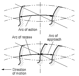
- Arc of action, Qt
- The arc of the pitch circle through which a tooth profile moves from the beginning to the end of contact with a mating profile.
- Arc of approach, Qa
- The arc of the pitch circle through which a tooth profile moves from its beginning of contact until the point of contact arrives at the pitch point.
- Arc of recess, Qr
- The arc of the pitch circle through which a tooth profile moves from contact at the pitch point until contact ends.
- Contact ratio, mc, ε
- The number of angular pitches through which a tooth surface rotates from the beginning to the end of contact.In a simple way, it can be defined as a measure of the average number of teeth in contact during the period in which a tooth comes and goes out of contact with the mating gear.
- Transverse contact ratio, mp, εα
- The contact ratio in a transverse plane. It is the ratio of the angle of action to the angular pitch. For involute gears it is most directly obtained as the ratio of the length of action to the base pitch.
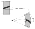
- Face contact ratio, mF, εβ
- The contact ratio in an axial plane, or the ratio of the face width to the axial pitch. For bevel and hypoid gears it is the ratio of face advance to circular pitch.
- Total contact ratio, mt, εγ
- The sum of the transverse contact ratio and the face contact ratio.

- mt = mp + mF
- Modified contact ratio, mo
- For bevel gears, the square root of the sum of the squares of the transverse and face contact ratios.

- Limit diameter
- Diameter on a gear at which the line of action intersects the maximum (or minimum for internal pinion) addendum circle of the mating gear. This is also referred to as the start of active profile, the start of contact, the end of contact, or the end of active profile.
- Start of active profile (SAP)
- Intersection of the limit diameter and the involute profile.
- Face advance
- Distance on a pitch circle through which a helical or spiral tooth moves from the position at which contact begins at one end of the tooth trace on the pitch surface to the position where contact ceases at the other end.
Tooth thickness nomeclature
-
Tooth thickness
-

Thickness relationships
-
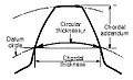
Chordal thickness
-

Tooth thickness measurement over pins
-
Span measurement
-
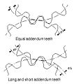
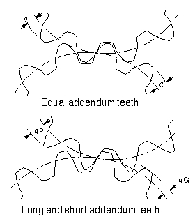
Long and short addendum teeth
- Circular thickness
- Length of arc between the two sides of a gear tooth, on the specified datum circle.
- Transverse circular thickness
- Circular thickness in the transverse plane.
- Normal circular thickness
- Circular thickness in the normal plane. In a helical gear it may be considered as the length of arc along a normal helix.
- Axial thickness
- In helical gears and worms, tooth thickness in an axial cross section at the standard pitch diameter.
- Base circular thickness
- In involute teeth, length of arc on the base circle between the two involute curves forming the profile of a tooth.
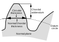
- Normal chordal thickness
- Length of the chord that subtends a circular thickness arc in the plane normal to the pitch helix. Any convenient measuring diameter may be selected, not necessarily the standard pitch diameter.
- Chordal addendum (chordal height)
- Height from the top of the tooth to the chord subtending the circular thickness arc. Any convenient measuring diameter may be selected, not necessarily the standard pitch diameter.
- Profile shift
- Displacement of the basic rack datum line from the reference cylinder, made non-dimensional by dividing by the normal module. It is used to specify the tooth thickness, often for zero backlash.
- Rack shift
- Displacement of the tool datum line from the reference cylinder, made non-dimensional by dividing by the normal module. It is used to specify the tooth thickness.
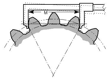
- Measurement over pins
- Measurement of the distance taken over a pin positioned in a tooth space and a reference surface. The reference surface may be the reference axis of the gear, a datum surface or either one or two pins positioned in the tooth space or spaces opposite the first. This measurement is used to determine tooth thickness.
- Span measurement
- Measurement of the distance across several teeth in a normal plane. As long as the measuring device has parallel measuring surfaces that contact on an unmodified portion of the involute, the measurement will be along a line tangent to the base cylinder. It is used to determine tooth thickness.
- Modified addendum teeth
- Teeth of engaging gears, one or both of which have non-standard addendum.
- Full-depth teeth
- Teeth in which the working depth equals 2.000 divided by the normal diametral pitch.
- Stub teeth
- Teeth in which the working depth is less than 2.000 divided by the normal diametral pitch.
- Equal addendum teeth
- Teeth in which two engaging gears have equal addendums.
- Long and short-addendum teeth
- Teeth in which the addendums of two engaging gears are unequal.
Pitch nomenclature
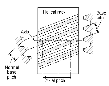
Pitch is the distance between a point on one tooth and the corresponding point on an adjacent tooth.[5] It is a dimension measured along a line or curve in the transverse, normal, or axial directions. The use of the single word pitch without qualification may be ambiguous, and for this reason it is preferable to use specific designations such as transverse circular pitch, normal base pitch, axial pitch.
-

Pitch
-

Tooth pitch
-
Base pitch relationships
-

Principal pitches
- Circular pitch, p
- Arc distance along a specified pitch circle or pitch line between corresponding profiles of adjacent teeth.
- Transverse circular pitch, pt
- Circular pitch in the transverse plane.
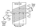
- Normal circular pitch, pn, pe
- Circular pitch in the normal plane, and also the length of the arc along the normal pitch helix between helical teeth or threads.
- Axial pitch, px
- Linear pitch in an axial plane and in a pitch surface. In helical gears and worms, axial pitch has the same value at all diameters. In gearing of other types, axial pitch may be confined to the pitch surface and may be a circular measurement. The term axial pitch is preferred to the term linear pitch. The axial pitch of a helical worm and the circular pitch of its worm gear are the same.
- Normal base pitch, pN, pbn
- An involute helical gear is the base pitch in the normal plane. It is the normal distance between parallel helical involute surfaces on the plane of action in the normal plane, or is the length of arc on the normal base helix. It is a constant distance in any helical involute gear.
- Transverse base pitch, pb, pbt
- In an involute gear, the pitch on the base circle or along the line of action. Corresponding sides of involute gear teeth are parallel curves, and the base pitch is the constant and fundamental distance between them along a common normal in a transverse plane.
- Diametral pitch (transverse), Pd
- Ratio of the number of teeth to the standard pitch diameter in inches.

- Normal diametral pitch, Pnd
- Value of diametral pitch in a normal plane of a helical gear or worm.

- Angular pitch, θN, τ
- Angle subtended by the circular pitch, usually expressed in radians.
 degrees or
  radians
Backlash
Main article: Backlash (engineering)Backlash is the error in motion that occurs when gears change direction. It exists because there is always some gap between the trailing face of the driving tooth and the leading face of the tooth behind it on the driven gear, and that gap must be closed before force can be transferred in the new direction. The term "backlash" can also be used to refer to the size of the gap, not just the phenomenon it causes; thus, one could speak of a pair of gears as having, for example, "0.1 mm of backlash." A pair of gears could be designed to have zero backlash, but this would presuppose perfection in manufacturing, uniform thermal expansion characteristics throughout the system, and no lubricant. Therefore, gear pairs are designed to have some backlash. It is usually provided by reducing the tooth thickness of each gear by half the desired gap distance. In the case of a large gear and a small pinion, however, the backlash is usually taken entirely off the gear and the pinion is given full sized teeth. Backlash can also be provided by moving the gears farther apart. The backlash of a gear train equals the sum of the backlash of each pair of gears, so in long trains backlash can become a problem.
For situations in which precision is important, such as instrumentation and control, backlash can be minimised through one of several techniques. For instance, the gear can be split along a plane perpendicular to the axis, one half fixed to the shaft in the usual manner, the other half placed alongside it, free to rotate about the shaft, but with springs between the two halves providing relative torque between them, so that one achieves, in effect, a single gear with expanding teeth. Another method involves tapering the teeth in the axial direction and providing for the gear to be slid in the axial direction to take up slack.
Shifting of gears
In some machines (e.g., automobiles) it is necessary to alter the gear ratio to suit the task. There are several methods of accomplishing this. For example:
- Manual transmission
- Automatic transmission
- Derailleur gears which are actually sprockets in combination with a roller chain
- Hub gears (also called epicyclic gearing or sun-and-planet gears)
There are several outcomes of gear shifting in motor vehicles. In the case of vehicle noise emissions, there are higher sound levels emitted when the vehicle is engaged in lower gears. The design life of the lower ratio gears is shorter so cheaper gears may be used (i.e. spur for 1st and reverse) which tends to generate more noise due to smaller overlap ratio and a lower mesh stiffness etc. than the helical gears used for the high ratios. This fact has been utilized in analyzing vehicle generated sound since the late 1960s, and has been incorporated into the simulation of urban roadway noise and corresponding design of urban noise barriers along roadways.[18]
Tooth profile
-

Profile of a spur gear
-
Undercut
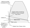
A profile is one side of a tooth in a cross section between the outside circle and the root circle. Usually a profile is the curve of intersection of a tooth surface and a plane or surface normal to the pitch surface, such as the transverse, normal, or axial plane.
The fillet curve (root fillet) is the concave portion of the tooth profile where it joins the bottom of the tooth space.2
As mentioned near the beginning of the article, the attainment of a non fluctuating velocity ratio is dependent on the profile of the teeth. Friction and wear between two gears is also dependent on the tooth profile. There are a great many tooth profiles that will give a constant velocity ratio, and in many cases, given an arbitrary tooth shape, it is possible to develop a tooth profile for the mating gear that will give a constant velocity ratio. However, two constant velocity tooth profiles have been by far the most commonly used in modern times. They are the cycloid and the involute. The cycloid was more common until the late 1800s; since then the involute has largely superseded it, particularly in drive train applications. The cycloid is in some ways the more interesting and flexible shape; however the involute has two advantages: it is easier to manufacture, and it permits the center to center spacing of the gears to vary over some range without ruining the constancy of the velocity ratio. Cycloidal gears only work properly if the center spacing is exactly right. Cycloidal gears are still used in mechanical clocks.
An undercut is a condition in generated gear teeth when any part of the fillet curve lies inside of a line drawn tangent to the working profile at its point of juncture with the fillet. Undercut may be deliberately introduced to facilitate finishing operations. With undercut the fillet curve intersects the working profile. Without undercut the fillet curve and the working profile have a common tangent.
Gear materials
 Wooden gears of a historic windmill
Numerous nonferrous alloys, cast irons, powder-metallurgy and plastics are used in the manufacture of gears. However steels are most commonly used because of their high strength to weight ratio and low cost. Plastic is commonly used where cost or weight is a concern. A properly designed plastic gear can replace steel in many cases because it has many desirable properties, including dirt tolerance, low speed meshing, and the ability to "skip" quite well.[19] Manufacturers have employed plastic gears to make consumer items affordable in items like copy machines, optical storage devices, VCRs, cheap dynamos, consumer audio equipment, servo motors, and printers.
The module system
Countries which have adopted the metric system generally use the module system. As a result, the term module is usually understood to mean the pitch diameter in millimeters divided by the number of teeth. When the module is based upon inch measurements, it is known as the English module to avoid confusion with the metric module. Module is a direct dimension, whereas diametral pitch is an inverse dimension (like "threads per inch"). Thus, if the pitch diameter of a gear is 40 mm and the number of teeth 20, the module is 2, which means that there are 2 mm of pitch diameter for each tooth.[20]
Manufacture
Gear Cutting simulation (length 1m35s) faster, high bitrate version.Gears are most commonly produced via hobbing, but they are also shaped, broached, cast, and in the case of plastic gears, injection molded. For metal gears the teeth are usually heat treated to make them hard and more wear resistant while leaving the core soft and tough. For large gears that are prone to warp a quench press is used.
Inspection
Gear geometry can be inspected and verified using various methods such as industrial CT scanning, coordinate-measuring machines, white light scanner or laser scanning. Particularly useful for plastic gears, industrial CT scanning can inspect internal geometry and imperfections such as porosity.
Gear model in modern physics
Modern physics adopted the gear model in different ways. In the nineteenth century, James Clerk Maxwell developed a model of electromagnetism in which magnetic field lines were rotating tubes of incompressible fluid. Maxwell used a gear wheel and called it an "idle wheel" to explain the electrical current as a rotation of particles in opposite directions to that of the rotating field lines.[21]
More recently, quantum physics uses "quantum gears" in their model. A group of gears can serve as a model for several different systems, such as an artificially constructed nanomechanical device or a group of ring molecules.[22]
The Three Wave Hypothesis compares the wave–particle duality to a bevel gear.[23]
See also
References
- ^ Howstuffworks "Transmission Basics"
- ^ Norton 2004, p. 462
- ^ M.J.T. Lewis: "Gearing in the Ancient World", Endeavour, Vol. 17, No. 3 (1993), pp. 110–115 (110)
- ^ "The Antikythera Mechanism Research Project: Why is it so important?", Retrieved 2011-01-10 Quote: "The Mechanism is thought to date from between 150 and 100 BC"
- ^ a b c d ANSI/AGMA 1012-G05, "Gear Nomenclature, Definition of Terms with Symbols".
- ^ Khurmi, R.S, Theory of Machines, S.CHAND
- ^ Doughtie and Vallance give the following information on helical gear speeds: "Pitch-line speeds of 4,000 to 7,000 fpm [20 to 36 m/s] are common with automobile and turbine gears, and speeds of 12,000 fpm [61 m/s] have been successfully used." -- p.281.
- ^ a b Helical gears, http://www.roymech.co.uk/Useful_Tables/Drive/Hellical_Gears.html, retrieved 2009-06-15.
- ^ McGraw Hill Encyclopedia of Science and Technology, "Gear", p. 742.
- ^ Canfield, Stephen (1997), "Gear Types", Dynamics of Machinery, Tennessee Tech University, Department of Mechanical Engineering, ME 362 lecture notes, http://gemini.tntech.edu/~slc3675/me361/lecture/grnts4.html.
- ^ Hilbert, David; Cohn-Vossen, Stephan (1952), Geometry and the Imagination (2nd ed.), New York: Chelsea, pp. 287, ISBN 978-0-8284-1087-8.
- ^ McGraw Hill Encyclopedia of Science and Technology, "Gear, p. 743.
- ^ Vallance Doughtie, p. 287.
- ^ Vallance Doughtie, pp. 280, 296.
- ^ Doughtie and Vallance, p. 290; McGraw Hill Encyclopedia of Science and Technology, "Gear", p. 743.
- ^ McGraw Hill Encyclopedia of Science and Technology, "Gear", p. 744.
- ^ a b ISO/DIS 21771:2007 : "Gears - Cylindrical Involute Gears and Gear Pairs - Concepts and Geometry", International Organization for Standardization, (2007)
- ^ C Michael Hogan and Gary L Latshaw,The Relationship Between Highway Planning and Urban Noise , Proceedings of the ASCE, Urban Transportation Division Specialty Conference by the American Society of Civil Engineers, Urban Transportation Division, May 21 to 23, 1973, Chicago, Illinois
- ^ Plastic gears are more reliable when engineers account for material properties and manufacturing processes during design. Zan Smith: Motion System Design, July 2000., http://motionsystemdesign.com/mechanical-pt/plastic-gears-more-reliable-0798/index.html
- ^ Oberg, E; Jones, F.D.; Horton, H.L.; Ryffell, H.H. (2000), Machinery's Handbook (26th ed.), Industrial Press, pp. 2649, ISBN 978-0-8311-2666-7.
- ^ Innovation in Maxwell's Electromagnetic Theory: Molecular Vortices, Displacement Current, and Light Daniel M. Siegel. University of Chicago Press (1991)
- ^ Angus MacKinnon arxiv (2002) http://arxiv.org/abs/cond-mat/0205647v2
- ^ M. I. Sanduk, Does the Three Wave Hypothesis Imply Hidden Structure? Apeiron, 14, No. 2, pp. 113-125 (2007)
Bibliography
- American Gear Manufacturers Association; American National Standards Institute (2005), Gear Nomenclature, Definitions of Terms with Symbols (ANSI/AGMA 1012-F90 ed.), American Gear Manufacturers Association, ISBN 9781555898465.
- McGraw-Hill (2007), McGraw-Hill Encyclopedia of Science and Technology (10th ed.), McGraw-Hill Professional, ISBN 978-0071441438.
- Norton, Robert L. (2004), Design of Machinery (3rd ed.), McGraw-Hill Professional, ISBN 9780071214964, http://books.google.com/?id=iepqRRbTxrgC.
- Vallance, Alex; Doughtie, Venton Levy (1964), Design of machine members (4th ed.), McGraw-Hill.
Further reading
- Buckingham, Earle (1949), Analytical Mechanics of Gears, McGraw-Hill Book Co..
- Coy, John J.; Townsend, Dennis P.; Zaretsky, Erwin V. (1985), Gearing, NASA Scientific and Technical Information Branch, NASA-RP-1152; AVSCOM Technical Report 84-C-15, http://ntrs.nasa.gov/archive/nasa/casi.ntrs.nasa.gov/20020070912_2002115489.pdf.
External links
- Geararium. Museum of gears and toothed wheels Antique, vintage, contemporary gears, sprockets, gear-related objects and interesting connections.
- Kinematic Models for Design Digital Library (KMODDL) Movies and photos of hundreds of working models at Cornell University
- Mathematical Tutorial for Gearing (Relating to Robotics)
- Animation of an Involute Rack and Pinion
- Explanation Of Various Gears & Their Applications
- "Gearology" – A short introductory course on gears and related components
- American Gear Manufacturers Association website
- Gear Solutions Magazine, Your Resource for Machines Services and Tooling for the Gear Industry
- Gear Technology, the Journal of Gear Manufacturing
Gear shapes Geartooth profiles Gear mechanics Examples In Bicycles: Cogset • Derailleur gears • Hub gear • Shaft-driven bicycle • Sprocket
In Horology: Wheel trainSee also Lower Pairs Higher Pairs Cam · GearsCategories:- Mechanical engineering
- Machines
- Kinematics
- Gears
- Tribology


Wikimedia Foundation. 2010.