- Brushed DC electric motor
-
A brushed DC motor is an internally commutated electric motor designed to be run from a direct current power source.
Contents
Simple two-pole DC motor
The following graphics illustrate a simple, two-pole, brushed, DC motor.
DC Motor Rotation 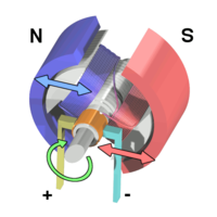
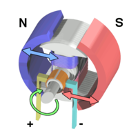
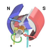

A simple DC electric motor. When the coil is powered, a magnetic field is generated around the armature. The left side of the armature is pushed away from the left magnet and drawn toward the right, causing rotation. The armature continues to rotate. When the armature becomes horizontally aligned, the commutator reverses the direction of current through the coil, reversing the magnetic field. The process then repeats.  Electric motors of various sizes
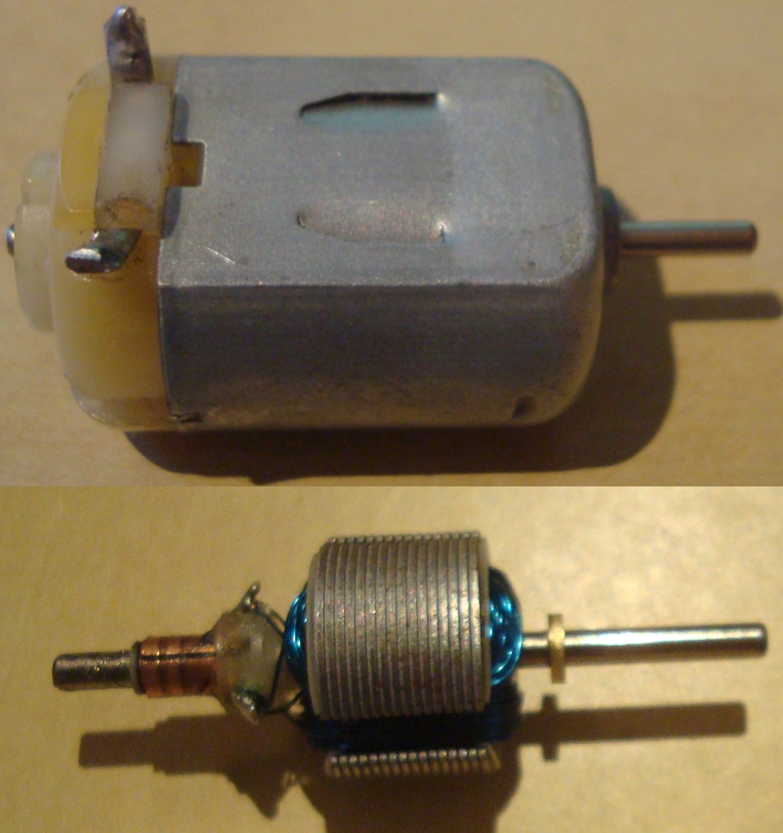
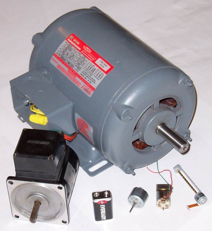
When a current passes through the coil wound around a soft iron core, the side of the positive pole is acted upon by an upwards force, while the other side is acted upon by a downward force. According to Fleming's left hand rule, the forces cause a turning effect on the coil, making it rotate. To make the motor rotate in a constant direction, "direct current" commutators make the current reverse in direction every half a cycle (in a two-pole motor) thus causing the motor to continue to rotate in the same direction.
A problem with the motor shown above is that when the plane of the coil is parallel to the magnetic field—i.e. when the rotor poles are 90 degrees from the stator poles—the torque is zero. In the pictures above, this occurs when the core of the coil is horizontal—the position it is just about to reach in the last picture on the right. The motor would not be able to start in this position. However, once it was started, it would continue to rotate through this position by momentum.
There is a second problem with this simple pole design. At the zero-torque position, both commutator brushes are touching (bridging) both commutator plates, resulting in a short-circuit. The power leads are shorted together through the commutator plates, and the coil is also short-circuited through both brushes (the coil is shorted twice, once through each brush independently). Note that this problem is independent of the non-starting problem above; even if there were a high current in the coil at this position, there would still be zero torque. The problem here is that this short uselessly consumes power without producing any motion (nor even any coil current.) In a low-current battery-powered demonstration this short-circuiting is generally not considered harmful. However, if a two-pole motor were designed to do actual work with several hundred watts of power output, this shorting could result in severe commutator overheating, brush damage, and potential welding of the brushes—if they were metallic—to the commutator. Carbon brushes, which are often used, would not weld. In any case, a short like this is very wasteful, drains batteries rapidly and, at a minimum, requires power supply components to be designed to much higher standards than would be needed just to run the motor without the shorting.
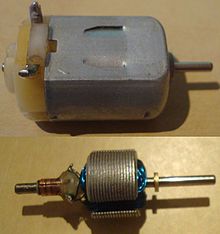 The inside of an electric DC motor.
One simple solution is to put a gap between the commutator plates which is wider than the ends of the brushes. This increases the zero-torque range of angular positions but eliminates the shorting problem; if the motor is started spinning by an outside force it will continue spinning. With this modification, it can also be effectively turned off simply by stalling (stopping) it in a position in the zero-torque (i.e. commutator non-contacting) angle range. This design is sometimes seen in homebuilt hobby motors, e.g. for science fairs and such designs can be found in some published science project books. A clear downside of this simple solution is that the motor now coasts through a substantial arc of rotation twice per revolution and the torque is pulsed. This may work for electric fans or to keep a flywheel spinning but there are many applications, even where starting and stopping are not necessary, for which it is completely inadequate, such as driving the capstan of a tape transport, or any instance where to speed up and slow down often and quickly is a requirement. Another disadvantage is that, since the coils have a measure of self inductance, current flowing in them cannot suddenly stop. The current attempts to jump the opening gap between the commutator segment and the brush, causing arcing.
Even for fans and flywheels, the clear weaknesses remaining in this design—especially that it is not self-starting from all positions—make it impractical for working use, especially considering the better alternatives that exist. Unlike the demonstration motor above, DC motors are commonly designed with more than two poles, are able to start from any position, and do not have any position where current can flow without producing electromotive power by passing through some coil. Many common small brushed DC motors used in toys and small consumer appliances, the simplest mass-produced DC motors to be found, have three-pole armatures. The brushes can now bridge two adjacent commutator segments without causing a short circuit. These three-pole armatures also have the advantage that current from the brushes either flows through two coils in series or through just one coil. Starting with the current in an individual coil at half its nominal value (as a result of flowing through two coils in series), it rises to its nominal value and then falls to half this value. The sequence then continues with current in the reverse direction. This results in a closer step-wise approximation to the ideal sinusoidal coil current, producing a more even torque than the two-pole motor where the current in each coil is closer to a square wave. Since current changes are half those of a comparable two-pole motor, arcing at the brushes is consequently less.
If the shaft of a DC motor is turned by an external force, the motor will act like a generator and produce an Electromotive force (EMF). During normal operation, the spinning of the motor produces a voltage, known as the counter-EMF (CEMF) or back EMF, because it opposes the applied voltage on the motor. The back EMF is the reason that the motor when free-running does not appear to have the same low electrical resistance as the wire contained in its winding. This is the same EMF that is produced when the motor is used as a generator (for example when an electrical load, such as a light bulb, is placed across the terminals of the motor and the motor shaft is driven with an external torque). Therefore, the total voltage drop across a motor consists of the CEMF voltage drop, and the parasitic voltage drop resulting from the internal resistance of the armature's windings. The current through a motor is given by the following equation:

The mechanical power produced by the motor is given by:

As an unloaded DC motor spins, it generates a backwards-flowing electromotive force that resists the current being applied to the motor. The current through the motor drops as the rotational speed increases, and a free-spinning motor has very little current. It is only when a load is applied to the motor that slows the rotor that the current draw through the motor increases.
"In an experiment of this kind made on a motor with separately excited magnets, the following figures were obtained:
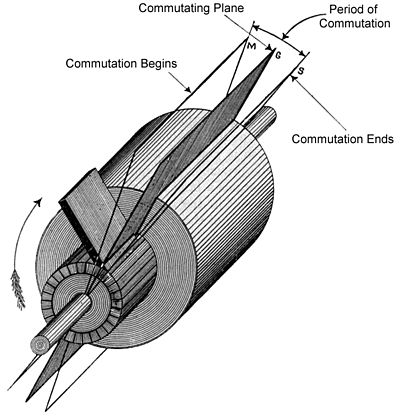
Apparently, if the motor had been helped on to run at 261.5 revolutions per minute, the current would have been reduced to zero. In the last result obtained, the current of 5.1 amperes was absorbed in driving the armature against its own friction at the speed of 195 revolutions per minute."[1]Revolutions per minute 0 50 100 160 180 195 Amperes 20 16.2 12.2 7.8 6.1 5.1 The commutating plane
In a dynamo, a plane through the centers of the contact areas where a pair of brushes touch the commutator and parallel to the axis of rotation of the armature is referred to as the commutating plane. In this diagram the commutating plane is shown for just one of the brushes, assuming the other brush made contact on the other side of the commutator with radial symmetry, 180 degrees from the brush shown.
Compensation for stator field distortion
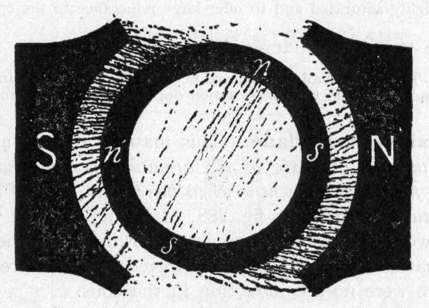
In a real dynamo, the field is never perfectly uniform. Instead, as the rotor spins it induces field effects which drag and distort the magnetic lines of the outer non-rotating stator.
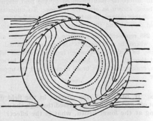 Exaggerated example of how the field is distorted by the rotor.
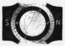 Iron filings show the distorted field across the rotor.
The faster the rotor spins, the further the degree of field distortion. Because the dynamo operates most efficiently with the rotor field at right angles the stator field, it is necessary to either retard or advance the brush position to put the rotor's field into the correct position to be at a right angle to the distorted field.
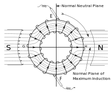 Centered position of the commutating plane if there were no field distortion effects.
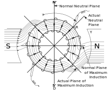 Actual position of the commutating plane to compensate for field distortion.
These field effects are reversed when the direction of spin is reversed. It is therefore difficult to build an efficient reversible commutated dynamo, since for highest field strength it is necessary to move the brushes to the opposite side of the normal neutral plane.
The effect can be considered to be somewhat similar to timing advance in an internal combustion engine. Generally a dynamo that has been designed to run at a certain fixed speed will have its brushes permanently fixed to align the field for highest efficiency at that speed.[2]
Motor design variations
DC motors
DC motors are commonly constructed with wound rotors and either wound or permanent magnet stators.
Wound stators
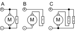 A: shunt
B: series
C: compound
f = field coilThe field coils have traditionally existed in four basic formats: separately excited (sepex), series-wound, shunt-wound, and a combination of the latter two; compound-wound.
In a series wound motor, the field coils are connected electrically in series with the armature coils (via the brushes). In a shunt wound motor, the field coils are connected in parallel, or "shunted" to the armature coils. In a separately excited (sepex) motor the field coils are supplied from an independent source, such as a motor-generator and the field current is unaffected by changes in the armature current. The sepex system was sometimes used in DC traction motors to facilitate control of wheelslip.
Permanent-magnet motors
Permanent magnet types have some performance advantages over direct-current excited synchronous types, and have become predominant in fractional horsepower applications. They are smaller, lighter, more efficient and reliable than other singly fed electric machines.[3]
Originally all large industrial DC motors used wound field or rotor magnets. Permanent magnets have traditionally only been useful on small motors because it was difficult to find a material capable of retaining a high-strength field. Only recently have advances in materials technology allowed the creation of high-intensity permanent magnets, such as neodymium magnets, allowing the development of compact, high-power motors without the extra real-estate of field coils and excitation means. But as these high performance permanent magnets become more applied in electric motor or generator systems, other problems are realized (see Permanent magnet synchronous generator).
Axial field motors
Traditionally, the field has been applied radially—in and away from the rotation axis of the motor. However some designs have the field flowing along the axis of the motor, with the rotor cutting the field lines as it rotates. This allows for much stronger magnetic fields, particularly if halbach arrays are employed. This, in turn, gives power to the motor at lower speeds. However, the focused flux density cannot rise about the limited residual flux density of the permanent magnet despite high coercivity and like all electric machine, the flux density of magnetic core saturation is the design constraint.
Speed control
Generally, the rotational speed of a DC motor is proportional to the voltage applied to it, and the torque is proportional to the current. Speed control can be achieved by variable battery tappings, variable supply voltage, resistors or electronic controls. The direction of a wound field DC motor can be changed by reversing either the field or armature connections but not both. This is commonly done with a special set of contactors (direction contactors).
The effective voltage can be varied by inserting a series resistor or by an electronically controlled switching device made of thyristors, transistors, or, formerly, mercury arc rectifiers.[4]
In a circuit known as a chopper, the average voltage applied to the motor is varied by switching the supply voltage very rapidly. As the "on" to "off" ratio is varied to alter the average applied voltage, the speed of the motor varies. The percentage "on" time multiplied by the supply voltage gives the average voltage applied to the motor. Therefore, with a 100 V supply and a 25% "on" time, the average voltage at the motor will be 25 V. During the "off" time, the armature's inductance causes the current to continue through a diode called a "flyback diode", in parallel with the motor. At this point in the cycle, the supply current will be zero, and therefore the average motor current will always be higher than the supply current unless the percentage "on" time is 100%. At 100% "on" time, the supply and motor current are equal. The rapid switching wastes less energy than series resistors. This method is also called pulse-width modulation (PWM) and is often controlled by a microprocessor. An output filter is sometimes installed to smooth the average voltage applied to the motor and reduce motor noise.
Since the series-wound DC motor develops its highest torque at low speed, it is often used in traction applications such as electric locomotives, and trams. Another application is starter motors for petrol and small diesel engines. Series motors must never be used in applications where the drive can fail (such as belt drives). As the motor accelerates, the armature (and hence field) current reduces. The reduction in field causes the motor to speed up until it destroys itself. This can also be a problem with railway motors in the event of a loss of adhesion since, unless quickly brought under control, the motors can reach speeds far higher than they would do under normal circumstances. This can not only cause problems for the motors themselves and the gears, but due to the differential speed between the rails and the wheels it can also cause serious damage to the rails and wheel treads as they heat and cool rapidly. Field weakening is used in some electronic controls to increase the top speed of an electric vehicle. The simplest form uses a contactor and field-weakening resistor; the electronic control monitors the motor current and switches the field weakening resistor into circuit when the motor current reduces below a preset value (this will be when the motor is at its full design speed). Once the resistor is in circuit, the motor will increase speed above its normal speed at its rated voltage. When motor current increases, the control will disconnect the resistor and low speed torque is made available.
One interesting method of speed control of a DC motor is the Ward Leonard control. It is a method of controlling a DC motor (usually a shunt or compound wound) and was developed as a method of providing a speed-controlled motor from an AC supply, though it is not without its advantages in DC schemes. The AC supply is used to drive an AC motor, usually an induction motor that drives a DC generator or dynamo. The DC output from the armature is directly connected to the armature of the DC motor (sometimes but not always of identical construction). The shunt field windings of both DC machines are independently excited through variable resistors. Extremely good speed control from standstill to full speed, and consistent torque, can be obtained by varying the generator and/or motor field current. This method of control was the de facto method from its development until it was superseded by solid state thyristor systems. It found service in almost any environment where good speed control was required, from passenger lifts through to large mine pit head winding gear and even industrial process machinery and electric cranes. Its principal disadvantage was that three machines were required to implement a scheme (five in very large installations, as the DC machines were often duplicated and controlled by a tandem variable resistor). In many applications, the motor-generator set was often left permanently running, to avoid the delays that would otherwise be caused by starting it up as required. Although electronic (thyristor) controllers have replaced most small to medium Ward-Leonard systems, some very large ones (thousands of horsepower) remain in service. The field currents are much lower than the armature currents, allowing a moderate sized thyristor unit to control a much larger motor than it could control directly. For example, in one installation, a 300 amp thyristor unit controls the field of the generator. The generator output current is in excess of 15,000 amperes, which would be prohibitively expensive (and inefficient) to control directly with thyristors.
Protection
To extend a D.C. motor’s service life, protective devices[5] and motor controllers are used to protect it from mechanical damage, excessive moisture, high dielectric stress and high temperature or thermal overloading[6]. These protective devices sense motor fault conditions[7] and either annunciate an alarm to notify the operator or automatically de-energize the motor when a faulty condition occurs. For overloaded conditions, motors are protected with thermal overload relays. Bi-metal thermal overload protectors are embedded in the motor's windings and made from two dissimilar metals. They are designed such that the bimetallic strips will bend in opposite directions when a temperature set point is reached to open the control circuit and de-energize the motor. Heaters are external thermal overload protectors connected in series with the motor’s windings and mounted in the motor contactor. Solder pot heaters melt in an overload condition, which cause the motor control circuit to de-energize the motor. Bimetallic heaters function the same way as embedded bimetallic protectors. Fuses and circuit breakers are overcurrent or short circuit protectors. Ground fault relays also provide overcurrent protection. They monitor the electrical current between the motor’s windings and earth system ground. In motor-generators, reverse current relays prevent the battery from discharging and motorizing the generator. Since D.C. motor field loss can cause a hazardous runaway or overspeed condition, loss of field relays[8] are connected in parallel with the motor’s field to sense field current. When the field current decreases below a set point, the relay will deenergize the motor’s armature. A locked rotor condition prevents a motor from accelerating after its starting sequence has been initiated. Distance relays protect motors from locked-rotor faults. Undervoltage motor protection is typically incorporated into motor controllers or starters. In addition, motors can be protected from overvoltages or surges with isolation transformers, power conditioning equipment, MOVs, arrestors and harmonic filters. Environmental conditions, such as dust, explosive vapors, water, and high ambient temperatures, can adversely affect the operation of a DC motor. To protect a motor from these environmental conditions, the National Electrical Manufacturers Association (NEMA) and the International Electrotechnical Commission (IEC) have standardized motor enclosure[9] designs based upon the environmental protection they provide from contaminants.
DC motor starters
The counter-emf aids the armature resistance to limit the current through the armature. When power is first applied to a motor, the armature does not rotate. At that instant the counter-emf is zero and the only factor limiting the armature current is the armature resistance. Usually the armature resistance of a motor is less than 1 Ω; therefore the current through the armature would be very large when the power is applied. This current can make an excessive voltage drop affecting other equipment in the circuit and even trip overload protective devices.
Therefore the need arises for an additional resistance in series with the armature to limit the current until the motor rotation can build up the counter-emf. As the motor rotation builds up, the resistance is gradually cut out.
Manual-starting rheostat
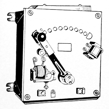
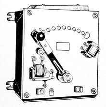 1917 DC motor manual starting rheostat with no-voltage and overload release features.
When electrical and DC motor technology was first developed, much of the equipment was constantly tended by an operator trained in the management of motor systems. The very first motor management systems were almost completely manual, with an attendant starting and stopping the motors, cleaning the equipment, repairing any mechanical failures, and so forth.
The first DC motor-starters were also completely manual, as shown in this image. Normally it took the operator about ten seconds to slowly advance the rheostat across the contacts to gradually increase input power up to operating speed. There were two different classes of these rheostats, one used for starting only, and one for starting and speed regulation. The starting rheostat was less expensive, but had smaller resistance elements that would burn out if required to run a motor at a constant reduced speed.
This starter includes a no-voltage magnetic holding feature, which causes the rheostat to spring to the off position if power is lost, so that the motor does not later attempt to restart in the full-voltage position. It also has overcurrent protection that trips the lever to the off position if excessive current over a set amount is detected. [10]
Three-point starter
 Three point starter
The incoming power is indicated as L1 and L2. The components within the broken lines form the three-point starter. As the name implies there are only three connections to the starter. The connections to the armature are indicated as A1 and A2. The ends of the field (excitement) coil are indicated as F1 and F2. In order to control the speed, a field rheostat is connected in series with the shunt field. One side of the line is connected to the arm of the starter (represented by an arrow in the diagram). The arm is spring-loaded so, it will return to the "Off" position when not held at any other position.
- On the first step of the arm, full line voltage is applied across the shunt field. Since the field rheostat is normally set to minimum resistance, the speed of the motor will not be excessive; additionally, the motor will develop a large starting torque.
- The starter also connects an electromagnet in series with the shunt field. It will hold the arm in position when the arm makes contact with the magnet.
- Meanwhile that voltage is applied to the shunt field, and the starting resistance limits the current to the armature.
- As the motor picks up speed counter-emf is built up; the arm is moved slowly to short.
Four-point starter
The four-point starter eliminates the drawback of the three-point starter. In addition to the same three points that were in use with the three-point starter, the other side of the line, L1, is the fourth point brought to the starter when the arm is moved from the "Off" position. The coil of the holding magnet is connected across the line. The holding magnet and starting resistors function identical as in the three-point starter.
- The possibility of accidentally opening the field circuit is quite remote. The four-point starter provides the no-voltage protection to the motor. If the power fails, the motor is disconnected from the line.
See also
- Torque and speed of a DC motor
- Digital electric motor
References
- ^ Hawkins Electrical Guide, p.359
- ^ Hawkins Electrical Guide
- ^ Gottlieb, I.M. (1994). Electric Motors & Control Techniques (2nd ed.). TAB Books.
- ^ Lander, Cyril W. (1993). "8 D.C. Machine Control". Power Electronics (3rd ed.). London: Mc Graw Hill International UK. ISBN 0-07-707714-8.
- ^ Herman, Stephen L. Electric Motor Control. 9th ed. Delmar, Cengage Learning, 2009. Page 12.
- ^ Malcolm Barnes. Practical variable speed drives and power electronics. Elsevier, Newnes, 2003. Page 151.
- ^ J. Lewis Blackburn. Protective relaying: principles and applications. CRC Press, 1998. Page 358.
- ^ Ohio Electric Motors. DC Motor Protection. Ohio Electric Motors. 2011. Archived 15 November 2011 at WebCite
- ^ H. Wayne Beaty and James L. Kirtley. Electric Motor Handbook. McGraw-Hill Professional, 1998. Page 97.
- ^ Hawkins Electrical Guide. Theo. Audel & Co.. 1917. pp. 664–669.
External links
Electric motors Broad motor categories 
Conventional
electric motorsUnusual electric motors Ball bearing • Homopolar • Piezoelectric • Ultrasonic • Electrostatic • Switched reluctance • Superconducting electric machine • Electrically powered spacecraft propulsionMotor
controllersSee also Categories:- Electric motors


Wikimedia Foundation. 2010.