- Inductance
-
Electromagnetism 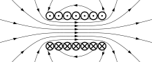
Electricity · Magnetism Lorentz force law · emf · Electromagnetic induction · Faraday’s law · Lenz's law · Displacement current · Maxwell's equations · EM field · Electromagnetic radiation · Liénard–Wiechert potential · Maxwell tensor · Eddy currentElectrical conduction · Electrical resistance · Capacitance · Inductance · Impedance · Resonant cavities · WaveguidesIn electromagnetism and electronics, inductance is the ability of an inductor to store energy in a magnetic field. Inductors generate an opposing voltage proportional to the rate of change in current in a circuit. This property also is called self-inductance to discriminate it from mutual inductance, describing the voltage induced in one electrical circuit by the rate of change of the electric current in another circuit.
The quantitative definition of the self inductance L of an electrical circuit in SI units (webers per ampere, known as henries) is
where v denotes the voltage in volts and i the current in amperes. The simplest solutions of this equation are a constant current with no voltage or a current changing linearly in time with a constant voltage.
The term 'inductance' was coined by Oliver Heaviside in February 1886.[1] It is customary to use the symbol L for inductance, possibly in honour of the physicist Heinrich Lenz.[2][3] The SI unit of inductance is the henry (H), named after American scientist and magnetic researcher Joseph Henry. 1 H = 1 Wb/A.
Inductance is caused by the magnetic field generated by electric currents according to Ampere's law. To add inductance to a circuit, electronic components called inductors are used, typically consisting of coils of wire to concentrate the magnetic field and to collect the induced voltage. This is analogous to adding capacitance to a circuit by adding capacitors. Capacitance is caused by the electric field generated by electric charge according to Gauss's law.
The generalization to the case of K electrical circuits with currents im and voltages vm reads
Inductance here is a symmetric matrix. The diagonal coefficients Lm,m are called coefficients of self inductance, the off-diagonal elements are called coefficients of mutual inductance. The coefficients of inductance are constant as long as no magnetizable material with nonlinear characteristics is involved. This is a direct consequence of the linearity of Maxwell's equations in the fields and the current density. The coefficients of inductance become functions of the currents in the nonlinear case, see nonlinear inductance.
Derivation from Faraday's law of inductance
The inductance equations above are a consequence of Maxwell's equations. There is a straightforward derivation in the important case of electrical circuits consisting of thin wires.
Consider a system of K wire loops, each with one or several wire turns. The flux linkage of loop m is given by
Here Nm denotes the number of turns in loop m, Φm the magnetic flux through this loop, and Lm,n are some constants. This equation follows from Ampere's law - magnetic fields and fluxes are linear functions of the currents. By Faraday's law of induction we have
where vm denotes the voltage induced in circuit m. This agrees with the definition of inductance above if the coefficients Lm,n are identified with the coefficients of inductance. Because the total currents Nnin contribute to Φm it also follows that Lm,n is proportional to the product of turns NmNn.
Inductance and magnetic field energy
Multiplying the equation for vm above with imdt and summing over m gives the energy transferred to the system in the time interval dt,
This must agree with the change of the magnetic field energy W caused by the currents.[4] The integrability condition
requires Lm,n=Ln,m. The inductance matrix Lm,n thus is symmetric. The integral of the energy transfer is the magnetic field energy as a function of the currents,
This equation also is a direct consequence of the linearity of Maxwell's equations. It is helpful to associate changing electric currents with a build-up or decrease of magnet field energy. The corresponding energy transfer requires or generates a voltage. A mechanical analogy in the K=1 case with magnetic field energy (1/2)Li2 is a body with mass M, velocity u and kinetic energy (1/2)Mu2. The rate of change of velocity (current) multiplied with mass (inductance) requires or generates a force (an electrical voltage).
Coupled inductors
Further information: Coupling (electronics) The circuit diagram representation of mutually coupled inductors. The two vertical lines between the inductors indicate a solid core that the wires of the inductor are wrapped around. "n:m" shows the ratio between the number of windings of the left inductor to windings of the right inductor. This picture also shows the dot convention.
Mutual inductance occurs when the change in current in one inductor induces a voltage in another nearby inductor. It is important as the mechanism by which transformers work, but it can also cause unwanted coupling between conductors in a circuit.
The mutual inductance, M, is also a measure of the coupling between two inductors. The mutual inductance by circuit i on circuit j is given by the double integral Neumann formula, see calculation techniques
The mutual inductance also has the relationship:
where
- M21 is the mutual inductance, and the subscript specifies the relationship of the voltage induced in coil 2 due to the current in coil 1.
- N1 is the number of turns in coil 1,
- N2 is the number of turns in coil 2,
- P21 is the permeance of the space occupied by the flux.
The mutual inductance also has a relationship with the coupling coefficient. The coupling coefficient is always between 1 and 0, and is a convenient way to specify the relationship between a certain orientation of inductor with arbitrary inductance:
where
- k is the coupling coefficient and 0 ≤ k ≤ 1,
- L1 is the inductance of the first coil, and
- L2 is the inductance of the second coil.
Once the mutual inductance, M, is determined from this factor, it can be used to predict the behavior of a circuit:
where
- V1 is the voltage across the inductor of interest,
- L1 is the inductance of the inductor of interest,
- dI1/dt is the derivative, with respect to time, of the current through the inductor of interest,
- dI2/dt is the derivative, with respect to time, of the current through the inductor that is coupled to the first inductor, and
- M is the mutual inductance.
The minus sign arises because of the sense the current I2 has been defined in the diagram. With both currents defined going into the dots the sign of M will be positive.[5]
When one inductor is closely coupled to another inductor through mutual inductance, such as in a transformer, the voltages, currents, and number of turns can be related in the following way:
where
- Vs is the voltage across the secondary inductor,
- Vp is the voltage across the primary inductor (the one connected to a power source),
- Ns is the number of turns in the secondary inductor, and
- Np is the number of turns in the primary inductor.
Conversely the current:
where
- Is is the current through the secondary inductor,
- Ip is the current through the primary inductor (the one connected to a power source),
- Ns is the number of turns in the secondary inductor, and
- Np is the number of turns in the primary inductor.
Note that the power through one inductor is the same as the power through the other. Also note that these equations don't work if both transformers are forced (with power sources).
When either side of the transformer is a tuned circuit, the amount of mutual inductance between the two windings determines the shape of the frequency response curve. Although no boundaries are defined, this is often referred to as loose-, critical-, and over-coupling. When two tuned circuits are loosely coupled through mutual inductance, the bandwidth will be narrow. As the amount of mutual inductance increases, the bandwidth continues to grow. When the mutual inductance is increased beyond a critical point, the peak in the response curve begins to drop, and the center frequency will be attenuated more strongly than its direct sidebands. This is known as overcoupling.
Calculation techniques
In the most general case, inductance can be calculated from Maxwell's equations. Many important cases can be solved using simplifications. Where high frequency currents are considered, with skin effect, the surface current densities and magnetic field may be obtained by solving the Laplace equation. Where the conductors are thin wires, self inductance still depends on the wire radius and the distribution of the current in the wire. This current distribution is approximately constant (on the surface or in the volume of the wire) for a wire radius much smaller than other length scales.
Mutual inductance
The mutual inductance by a filamentary circuit i on a filamentary circuit j is given by the double integral Neumann formula[6]
The symbol μ0 denotes the magnetic constant (4π×10−7 H/m), Ci and Cj are the curves spanned by the wires, Rij is the distance between two points. See a derivation of this equation.
Self-inductance
Formally the self-inductance of a wire loop would be given by the above equation with i = j. The problem, however, is that 1/R now becomes infinite, making it necessary to take the finite wire radius a and the distribution of the current in the wire into account. There remain the contribution from the integral over all points with |R| ≥ a/2 and a correction term,
Here a and l denote radius and length of the wire, and Y is a constant that depends on the distribution of the current in the wire: Y = 0 when the current flows in the surface of the wire (skin effect), Y = 1/4 when the current is homogeneous across the wire. This approximation is accurate when the wires are long compared to their cross-sectional dimensions. Here is a derivation of this equation.
Method of images
In some cases different current distributions generate the same magnetic field in some section of space. This fact may be used to relate self inductances (method of images). As an example consider the two systems:
- A wire at distance d/2 in front of a perfectly conducting wall (which is the return)
- Two parallel wires at distance d, with opposite current
The magnetic field of the two systems coincides (in a half space). The magnetic field energy and the inductance of the second system thus are twice as large as that of the first system.
Relation between inductance and capacitance
Inductance per length L' and capacitance per length C' are related to each other in the special case of transmission lines consisting of two parallel perfect conductors of arbitrary but constant cross section,[7]
Here ε and µ denote dielectric constant and magnetic permeability of the medium the conductors are embedded in. There is no electric and no magnetic field inside the conductors (complete skin effect, high frequency). Current flows down on one line and returns on the other. Signals will propagate along the transmission line at the speed of electromagnetic radiation in the non-conductive medium enveloping the conductors.
Self-inductance of simple electrical circuits in air
The self-inductance of many types of electrical circuits can be given in closed form. Examples are listed in the table.
Inductance of simple electrical circuits in air Type Inductance / μ0 Comment Single layer
solenoid[8]

 for w << 1
 for w >> 1
N: Number of turns
r: Radius
l: Length
w = r/l
m = 4w2
E,K: Elliptic integralsCoaxial cable,
high frequency
a1: Outer radius
a: Inner radius
l: LengthCircular loop[9] 
r: Loop radius
a: Wire radiusRectangle[10] 
b, d: Border length
d >> a, b >> a
a: Wire radiusPair of parallel
wires
a: Wire radius
d: Distance, d ≥ 2a
l: Length of pairPair of parallel
wires, high
frequency
a: Wire radius
d: Distance, d ≥ 2a
l: Length of pairWire parallel to
perfectly
conducting wall
a: Wire radius
d: Distance, d ≥ a
l: LengthWire parallel to
conducting wall,
high frequency
a: Wire radius
d: Distance, d ≥ a
l: LengthThe symbol μ0 denotes the magnetic constant (4π×10−7 H/m). For high frequencies the electric current flows in the conductor surface (skin effect), and depending on the geometry it sometimes is necessary to distinguish low and high frequency inductances. This is the purpose of the constant Y: Y = 0 when the current is uniformly distributed over the surface of the wire (skin effect), Y = 1/4 when the current is uniformly distributed over the cross section of the wire. In the high frequency case, if conductors approach each other, an additional screening current flows in their surface, and expressions containing Y become invalid. Details for some circuit types are available on another page.
Phasor circuit analysis and impedance
Using phasors, the equivalent impedance of an inductance is given by:
where
- j is the imaginary unit,
- L is the inductance,
- ω = 2πf is the angular frequency,
- f is the frequency and
- Lω = XL is the inductive reactance.
Nonlinear inductance
Many inductors make use of magnetic materials. These materials over a large enough range exhibit a nonlinear permeability with such effects as saturation. This in-turn makes the resulting inductance a function of the applied current. Faraday's Law still holds but inductance is ambiguous and is different whether you are calculating circuit parameters or magnetic fluxes.
The secant or large-signal inductance is used in flux calculations. It is defined as:
The differential or small-signal inductance, on the other hand, is used in calculating voltage. It is defined as:
The circuit voltage for a nonlinear inductor is obtained via the differential inductance as shown by Faraday's Law and the chain rule of calculus.
There are similar definitions for nonlinear mutual inductances.
See also
References
- ^ Heaviside, O. Electrician. Feb. 12, 1886, p. 271. See reprint
- ^ Glenn Elert (1998–2008). "The Physics Hypertextbook: Inductance". http://hypertextbook.com/physics/electricity/inductance/.
- ^ Michael W. Davidson (1995–2008). "Molecular Expressions: Electricity and Magnetism Introduction: Inductance". http://micro.magnet.fsu.edu/electromag/electricity/inductance.html.
- ^ The kinetic energy of the drifting electrons is many orders of magnitude smaller than W, except for nanowires.
- ^ Mahmood Nahvi, Joseph Edminister (2002). Schaum's outline of theory and problems of electric circuits. McGraw-Hill Professional. p. 338. ISBN 0071393072. http://books.google.com/?id=nrxT9Qjguk8C&pg=PA338.
- ^ Neumann, F. E. (1847). "Allgemeine Gesetze der inducirten elektrischen Ströme". Abhandlungen der Königlichen Akademie der Wissenschaften zu Berlin, aus dem Jahre 1845: 1–87.
- ^ Jackson, J. D. (1975). Classical Electrodynamics. Wiley. p. 262.
- ^ Lorenz, L. (1879). "Über die Fortpflanzung der Elektrizität". Annalen der Physik VII: 161–193. (The expression given is the inductance of a cylinder with a current around its surface)..
- ^ Elliott, R. S. (1993). Electromagnetics. New York: IEEE Press. Note: The constant -3/2 in the result for a uniform current distribution is wrong.
- ^ Rosa, E.B. (1908). "The Self and Mutual Inductances of Linear Conductors". Bulletin of the Bureau of Standards 4 (2): 301–344.
General references
- Frederick W. Grover (1952). Inductance Calculations. Dover Publications, New York.
- Griffiths, David J. (1998). Introduction to Electrodynamics (3rd ed.). Prentice Hall. ISBN 0-13-805326-X.
- Wangsness, Roald K. (1986). Electromagnetic Fields (2nd ed.). Wiley. ISBN 0-471-81186-6.
- Hughes, Edward. (2002). Electrical & Electronic Technology (8th ed.). Prentice Hall. ISBN 0-582-40519-X.
- Küpfmüller K., Einführung in die theoretische Elektrotechnik, Springer-Verlag, 1959.
- Heaviside O., Electrical Papers. Vol.1. – L.; N.Y.: Macmillan, 1892, p. 429-560.
- F. Langford-Smith, editor, 1953, Radiotron Designer's Handbook, 4th Edition, Wireless Press for Amalgamated Wireless Valve Company PTY, LTD, Sydney, Australia together with Eectron Tube Division of the Radio Corporation of America [RCA], Harrison, N. J. No Library of Congress Card Catalog Number or ISBN. Chapter 10 pp. 429-448 Calculation of Inductance includes a wealth of approximate formulas and nomographs for single-layer solenoids of various coil diameters and pitch of windings and lengths, the effects of screens, formulas and nomographs for multilayer coils (long and short), for toroidal coils, for flat spirals, and a nomograph for the mutual inductance between coaxial solenoids. With 56 references.
External links
Categories:- Electrodynamics
- Physical quantities


Wikimedia Foundation. 2010.