- Coaxial cable
-


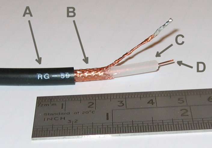
RG-59 flexible coaxial cable composed of: A: outer plastic sheath
B: woven copper shield
C: inner dielectric insulator
D: copper coreCoaxial cable, or coax, has an inner conductor surrounded by a flexible, tubular insulating layer, surrounded by a tubular conducting shield. The term coaxial comes from the inner conductor and the outer shield sharing the same geometric axis. Coaxial cable was invented by English engineer and mathematician Oliver Heaviside, who patented the design in 1880.[1]
Coaxial cable is used as a transmission line for radio frequency signals. Its applications include feedlines connecting radio transmitters and receivers with their antennas, computer network (Internet) connections, and distributing cable television signals. One advantage of coax over other types of radio transmission line is that in an ideal coaxial cable the electromagnetic field carrying the signal exists only in the space between the inner and outer conductors. This allows coaxial cable runs to be installed next to metal objects such as gutters without the power losses that occur in other types of transmission lines. Coaxial cable also provides protection of the signal from external electromagnetic interference.
Coaxial cable differs from other shielded cable used for carrying lower frequency signals, such as audio signals, in that the dimensions of the cable are controlled to give a precise, constant conductor spacing, which is needed for it to function efficiently as a radio frequency transmission line.
Contents
Description
 Coaxial cable cutaway
Coaxial cable conducts electrical signal using an inner conductor (usually a flexible solid or stranded copper wire) surrounded by an insulating layer and all enclosed by a shield layer, typically a woven metallic braid; the cable is often protected by an outer insulating jacket. Normally, the shield is kept at ground potential and a voltage is applied to the center conductor to carry electrical signals. The advantage of coaxial design is that the electric and magnetic fields are confined to the dielectric with little leakage outside the shield. Conversely, electric and magnetic fields outside the cable are largely kept from causing interference to signals inside the cable. This property makes coaxial cable a good choice for carrying weak signals that cannot tolerate interference from the environment or for higher electrical signals that must not be allowed to radiate or couple into adjacent structures or circuits.[2]
Common applications of coaxial cable include video and CATV distribution, RF and microwave transmission, and computer and instrumentation data connections.[3]
The characteristic impedance of the cable (Z0) is determined by the dielectric constant of the inner insulator and the radiuses of the inner and outer conductors. A controlled cable characteristic impedance is important because the source and load impedance should be matched to ensure maximum power transfer and minimum Standing Wave Ratio. Other important properties of coaxial cable include attenuation as a function of frequency, voltage handling capability, and shield quality.[2]
Construction
Coaxial cable design choices affect physical size, frequency performance, attenuation, power handling capabilities, flexibility, strength and cost. The inner conductor might be solid or stranded; stranded is more flexible. To get better high-frequency performance, the inner conductor may be silver plated. Sometimes copper-plated iron wire is used as an inner conductor. [4]
The insulator surrounding the inner conductor may be solid plastic, a foam plastic, or may be air with spacers supporting the inner wire. The properties of dielectric control some electrical properties of the cable. A common choice is a solid polyethylene (PE) insulator, used in lower-loss cables. Solid Teflon (PTFE) is also used as an insulator. Some coaxial lines use air (or some other gas) and have spacers to keep the inner conductor from touching the shield.
Many conventional coaxial cables use braided copper wire forming the shield. This allows the cable to be flexible, but it also means there are gaps in the shield layer, and the inner dimension of the shield varies slightly because the braid cannot be flat. Sometimes the braid is silver plated. For better shield performance, some cables have a double-layer shield. [4] The shield might be just two braids, but it is more common now to have a thin foil shield covered by a wire braid. Some cables may invest in more than two shield layers, such as "quad-shield" which uses four alternating layers of foil and braid. Other shield designs sacrifice flexibility for better performance; some shields are a solid metal tube. Those cables cannot take sharp bends, as the shield will kink, causing losses in the cable.
For high power radio-frequency transmission up to about 1 GHz coaxial cable with a solid copper outer conductor is available in sizes of 0.25 inch upwards. The outer conductor is rippled like a bellows to permit flexibility and the inner conductor is held in position by a plastic spiral to approximate an air dielectric. [4]
Coaxial cables require an internal structure of an insulating (dielectric) material to maintain the spacing between the center conductor and shield. The dielectric losses increase in this order: Ideal dielectric (no loss), vacuum, air, Polytetrafluoroethylene (PTFE), polyethylene foam, and solid polyethylene. A low relative permittivity allows for higher frequency usage. An inhomogeneous dielectric needs to be compensated by a non-circular conductor to avoid current hot-spots.
Most cables have a solid dielectric; others have a foam dielectric which contains as much air as possible to reduce the losses. Foam coax will have about 15% less attenuation but can absorb moisture—especially at its many surfaces—in humid environments, increasing the loss. Supports shaped like stars or spokes are even better but more expensive. Still more expensive were the air spaced coaxials used for some inter-city communications in the middle 20th Century. The center conductor was suspended by polyethylene discs every few centimeters. In some low loss coaxial cables such as an RG-62 type, the inner conductor is supported by a spiral strand of polyethylene, so that an air space exists between most of the conductor and the inside of the jacket. The lower dielectric constant of air allows for a greater inner diameter at the same impedance and a greater outer diameter at the same cutoff frequency, lowering ohmic losses. Inner conductors are sometimes silver plated to smooth the surface and reduce losses due to skin effect. [4] A rough surface prolongs the path for the current and concentrates the current at peaks and thus increases ohmic losses.
The insulating jacket can be made from many materials. A common choice is PVC, but some applications may require fire-resistant materials. Outdoor applications may require the jacket to resist ultraviolet light and oxidation. For internal chassis connections the insulating jacket may be omitted.
Signal propagation
Open wire transmission lines have the property that the electromagnetic wave propagating down the line extends into the space surrounding the parallel wires. These lines have low loss, but also have undesirable characteristics. They cannot be bent, twisted or otherwise shaped without changing their characteristic impedance, causing reflection of the signal back toward the source. They also cannot be run along or attached to anything conductive, as the extended fields will induce currents in the nearby conductors causing unwanted radiation and detuning of the line. Coaxial lines solve this problem by confining virtually all of the electromagnetic wave to the area inside the cable. Coaxial lines can therefore be bent and moderately twisted without negative effects, and they can be strapped to conductive supports without inducing unwanted currents in them.
In radio-frequency applications up to a few gigahertz, the wave propagates primarily in the transverse electric magnetic (TEM) mode, which means that the electric and magnetic fields are both perpendicular to the direction of propagation. However, above a certain cutoff frequency, transverse electric (TE) and/or transverse magnetic (TM) modes can also propagate, as they do in a waveguide. It is usually undesirable to transmit signals above the cutoff frequency, since it may cause multiple modes with different phase velocities to propagate, interfering with each other. The outer diameter is roughly inversely proportional to the cutoff frequency. A propagating surface-wave mode that does not involve or require the outer shield but only a single central conductor also exists in coax but this mode is effectively suppressed in coax of conventional geometry and common impedance. Electric field lines for this [TM] mode have a longitudinal component and require line lengths of a half-wavelength or longer.
Coaxial cable may be viewed as a type of waveguide. Power is transmitted through the radial electric field and the circumferential magnetic field in the TEM00 transverse mode. This is the dominant mode from zero frequency (DC) to an upper limit determined by the electrical dimensions of the cable.[5]
Connectors
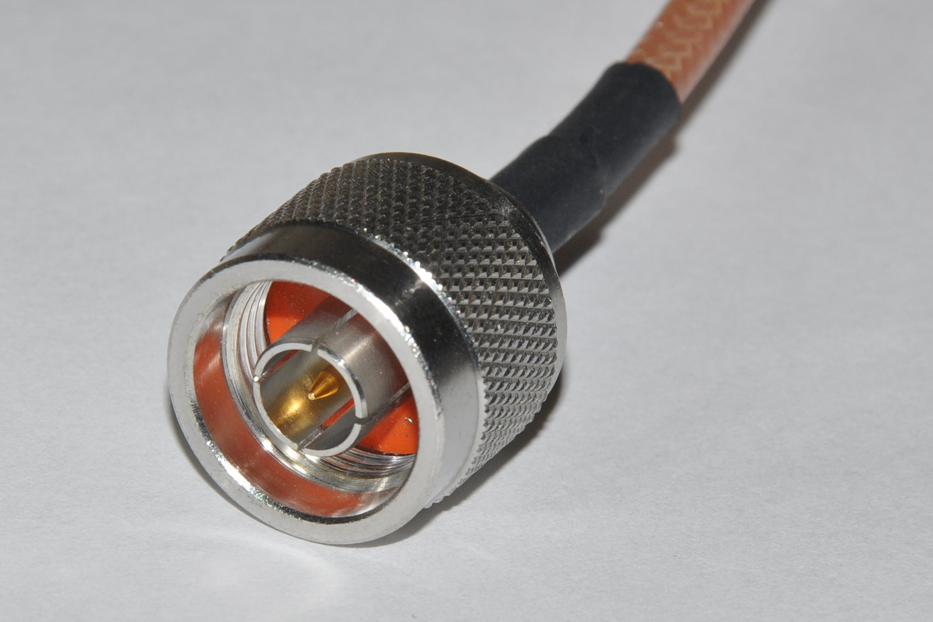
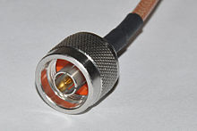 A coaxial connector (male N-type).Main article: RF connector
The ends of coaxial cables usually terminate with connectors. Coaxial connectors are designed to maintain a coaxial form across the connection and have the same well-defined impedance as the attached cable. [4] Connectors are often plated with high-conductivity metals such as silver or gold. Due to the skin effect, the RF signal is only carried by the plating and does not penetrate to the connector body. Although silver oxidizes quickly, the silver oxide that is produced is still conductive. While this may pose a cosmetic issue, it does not degrade performance.
Important parameters
Coaxial cable is a particular kind of transmission line, so the circuit models developed for general transmission lines are appropriate. See Telegrapher's equation.
 Schematic representation of the elementary components of a transmission line.
 Schematic representation of a coaxial transmission line, showing the characteristic impedance Z0.
Physical parameters
In the following section, these symbols are used:
- Length of the cable, h.
- Outside diameter of inner conductor, d.
- Inside diameter of the shield, D.
- Dielectric constant of the insulator,
 . The dielectric constant is often quoted as the relative dielectric constant
  referred to the dielectric constant of free space
  :
:  . When the insulator is a mixture of different dielectric materials (e.g., polyethylene foam is a mixture of polyethylene and air), then the term effective dielectric constant
  is often used.
 - Magnetic permeability of the insulator, μ. Permeability is often quoted as the relative permeability μr referred to the permeability of free space μ0: μ = μrμ0. The relative permeability will almost always be 1.
Fundamental electrical parameters
- Shunt capacitance per unit length, in farads per metre.[6]
- Series inductance per unit length, in henrys per metre.
- Series resistance per unit length, in ohms per metre. The resistance per unit length is just the resistance of inner conductor and the shield at low frequencies. At higher frequencies, skin effect increases the effective resistance by confining the conduction to a thin layer of each conductor.
- Shunt conductance per unit length, in siemens per metre. The shunt conductance is usually very small because insulators with good dielectric properties are used (a very low loss tangent). At high frequencies, a dielectric can have a significant resistive loss.
Derived electrical parameters
- Characteristic impedance in ohms (Ω). Neglecting resistance per unit length for most coaxial cables, the characteristic impedance is determined from the capacitance per unit length (C) and the inductance per unit length (L). The simplified expression is (
 ). Those parameters are determined from the ratio of the inner (d) and outer (D) diameters and the dielectric constant (). The characteristic impedance is given by[7]
-
- Assuming the dielectric properties of the material inside the cable do not vary appreciably over the operating range of the cable, this impedance is frequency independent above about five times the shield cutoff frequency. For typical coaxial cables, the shield cutoff frequency is 600 (RG-6A) to 2,000 Hz (RG-58C).[8]
- Attenuation (loss) per unit length, in decibels per meter. This is dependent on the loss in the dielectric material filling the cable, and resistive losses in the center conductor and outer shield. These losses are frequency dependent, the losses becoming higher as the frequency increases. Skin effect losses in the conductors can be reduced by increasing the diameter of the cable. A cable with twice the diameter will have half the skin effect resistance. Ignoring dielectric and other losses, the larger cable would halve the dB/meter loss. In designing a system, engineers consider not only the loss in the cable, but also the loss in the connectors.
- Velocity of propagation, in meters per second. The velocity of propagation depends on the dielectric constant and permeability (which is usually 1).
- Single mode band. In coaxial cable, the dominant mode (the mode with the lowest cutoff frequency), is the TEM mode, which has a cutoff frequency of zero; it propagates all the way down to d.c. The mode with the next lowest cutoff is the TE11 mode. This mode has one 'wave' (two reversals of polarity) in going around the circumference of the cable. To a good approximation, the condition for the TE11 mode to propagate is that the wavelength in the dielectric is no longer than the average circumference of the insulator; that is that the frequency is at least
-
 .
.
- Hence the cable is single-mode from to d.c. up to this frequency, and might in practice be used up to 90%[9] of this frequency.
- Peak Voltage. The peak voltage is set by the breakdown voltage of the insulator. One website[10] gives:
-

- where
- Smils is the insulator's breakdown voltage in volts per mil
- din is the inner diameter in inches
- The 1150 factor converts inches (diameter) to mils (radius) and log10 to ln.
- The above expression may be rewritten[11] as

- where
- S is the insulator's breakdown voltage in volts per meter
- d is the inner diameter in meters
- The calculated peak voltage is often reduced by a safety factor.
Choice of impedance
The best coaxial cable impedances in high-power, high-voltage and low-attenuation applications were experimentally determined at Bell Laboratories in 1929 to be 30, 60, and 77 Ω respectively. For a coaxial cable with air dielectric and a shield of a given inner diameter, the attenuation is minimized by choosing the diameter of the inner conductor to give a characteristic impedance of 76.7 Ω.[12] When more common dielectrics are considered, the best-loss impedance drops down to a value between 52–64 Ω. Maximum power handling is achieved at 30 Ω.[13]
The approximate impedance required to match a centre-fed dipole antenna in free space (i.e. a dipole without ground reflections) is 73 Ω, so 75 Ω coax was commonly used for connecting shortwave antennas to receivers. These typically involve such low levels of RF power that power handling and high-voltage breakdown characteristics are unimportant when compared to attenuation. Likewise with CATV, although many broadcast TV installations and CATV headends use 300 Ω folded dipole antennas to receive off-the-air signals, 75 Ω coax makes a convenient 4:1 balun transformer for these as well as possessing low attenuation.
The arithmetic mean between 30 Ω and 77 Ω is 53.5 Ω; the geometric mean is 48 Ω. The selection of 50 Ω as a compromise between power handling capability and attenuation is generally cited as the reason for the number.[citation needed] 50 Ω also works out well because it corresponds very closely to the drive impedance of a half-wave dipole in real environments, and provides an acceptable match to the drive impedance of a quarter-wave monopole as well.
RG-62 is a 93 Ω coaxial cable originally used in mainframe computer networks in the 1970s and early 1980s (it was the cable used to connect IBM 3270 terminals to IBM 3274/3174 terminal cluster controllers). Later, some manufacturers of LAN equipment, such as Datapoint for ARCNET, adopted RG-62 as their coaxial cable standard. The cable has the lowest capacitance per unit length when compared to other coaxial cables of similar size. Capacitance is the enemy of square-wave data transmission (in particular, it slows down edge transitions) and this is a much more important factor for baseband digital data transmission than power handling or attenuation.
All of the components of a coaxial system should have the same impedance to reduce internal reflections at connections between components. Such reflections may cause signal attenuation; multiple reflections may cause the original signal to be followed by one or more echos. In analog video or TV systems this causes ghosting in the image. Reflections also introduce standing waves which cause increased losses and can even result in cable dielectric breakdown with high-power transmission (see Impedance matching).
Issues
Signal leakage
Signal leakage is the passage of electromagnetic fields through the shield of a cable and occurs in both directions. Ingress is the passage of an outside signal into the cable and can result in noise and disruption of the desired signal. Egress is the passage of signal intended to remain within the cable into the outside world and can result in a weaker signal at the end of the cable and radio frequency interference to nearby devices.
For example, in the United States, signal leakage from cable television systems is regulated by the FCC, since cable signals use the same frequencies as aeronautical and radionavigation bands. CATV operators may also choose to monitor their networks for leakage to prevent ingress. Outside signals entering the cable can cause unwanted noise and picture ghosting. Excessive noise can overwhelm the signal, making it useless.
An ideal shield would be a perfect conductor with no holes, gaps or bumps connected to a perfect ground. However, a smooth solid copper shield would be heavy, inflexible, and expensive. Practical cables must make compromises between shield efficacy, flexibility and cost, such as the corrugated surface of hardline, flexible braid, or foil shields. Since the shields are not perfect conductors, electric fields can exist inside the shield, thus allowing radiating electromagnetic fields to go through the shield.
Consider the skin effect. The magnitude of an alternating current in a conductor decays exponentially with distance beneath the surface, with the depth of penetration being proportional to the square root of the resistivity. This means that in a shield of finite thickness, some small amount of current will still be flowing on the opposite surface of the conductor. With a perfect conductor (i.e., zero resistivity), all of the current would flow at the surface, with no penetration into and through the conductor. Real cables have a shield made of an imperfect, although usually very good, conductor, so there will always be some leakage.
The gaps or holes, allow some of the electromagnetic field to penetrate to the other side. For example, braided shields have many small gaps. The gaps are smaller when using a foil (solid metal) shield, but there is still a seam running the length of the cable. Foil becomes increasingly rigid with increasing thickness, so a thin foil layer is often surrounded by a layer of braided metal, which offers greater flexibility for a given cross-section.
This type of leakage can also occur at locations of poor contact between connectors at either end of the cable.
Ground loops
A continuous current, even if small, along the imperfect shield of a coaxial cable can cause visible or audible interference. In CATV systems distributing analog signals the potential difference between the coaxial network and the electrical grounding system of a house can cause a visible "hum bar" in the picture. This appears as a wide horizontal distortion bar in the picture that scrolls slowly upward. Such differences in potential can be reduced by proper bonding to a common ground at the house. See ground loop.
Induction
External current sources like switched-mode power supplies create a voltage across the inductance of the outer conductor between sender and receiver. The effect is less when there are several parallel cables, as this reduces the inductance and therefore the voltage. Because the outer conductor carries the reference potential for the signal on the inner conductor, the receiving circuit measures the wrong voltage.
Transformer effect
The transformer effect is sometimes used to mitigate the effect of currents induced in the shield. The inner and outer conductors form the primary and secondary winding of the transformer, and the effect is enhanced in some high quality cables that have an outer layer of mu-metal. Because of this 1:1 transformer, the aforementioned voltage across the outer conductor is transformed onto the inner conductor so that the two voltages can be cancelled by the receiver. Many sender and receivers have means to reduce the leakage even further. They increase the transformer effect by passing the whole cable through a ferrite core sometimes several times.
Common mode current and radiation
Common mode current occurs when stray currents in the shield flow in the same direction as the current in the center conductor, causing the coax to radiate.
Most of the shield effect in coax results from opposing currents in the center conductor and shield creating opposite magnetic fields that cancel, and thus do not radiate. The same effect helps ladder line. However, ladder line is extremely sensitive to surrounding metal objects which can enter the fields before they completely cancel. Coax does not have this problem since the field is enclosed in the shield. However, it is still possible for a field to form between the shield and other connected objects, such as the antenna the coax feeds. The current formed by the field between the antenna and the coax shield would flow in the same direction as the current in the center conductor, and thus not be canceled, and would actually cause energy to radiate from the coax itself, making it appear to be part of the antenna, affecting the radiation pattern of the antenna and possibly introducing dangerous radio frequency energy into areas near people, with the risk of radiation burns if the coax is being used for sufficiently high power transmissions. A properly placed and sized balun can prevent common mode radiation in coax.
Miscellaneous
Some senders and receivers use only a limited range of frequencies and block all others by means of an isolating transformer. Such a transformer breaks the shield for high frequencies. Still others avoid the transformer effect altogether by using two capacitors. If the capacitor for the outer conductor is implemented as one thin gap in the shield, no leakage at high frequencies occurs. At high frequencies, beyond the limits of coaxial cables, it becomes more efficient to use other types of transmission line such as wave guides or optical fiber, which offer low leakage (and much lower losses) around 200 THz and good isolation for all other frequencies.
Standards
Most coaxial cables have a characteristic impedance of either 50, 52, 75, or 93 Ω. The RF industry uses standard type-names for coaxial cables. Thanks to television, RG-6 is the most commonly-used coaxial cable for home use, and the majority of connections outside Europe are by F connectors.
A series of standard types of coaxial cable were specified for military uses, in the form "RG-#" or "RG-#/U". They date from World War II and were listed in MIL-HDBK-216 published in 1962. These designations are now obsolete. The RG designation stands for Radio Guide, the U designation stands for Universal. The current military standard is MIL-SPEC MIL-C-17. MIL-C-17 numbers, such as "M17/75-RG214," are given for military cables and manufacturer's catalog numbers for civilian applications. However, the RG-series designations were so common for generations that they are still used, although critical users should be aware that since the handbook is withdrawn there is no standard to guarantee the electrical and physical characteristics of a cable described as "RG-# type". The RG designators are mostly used to identify compatible connectors that fit the inner conductor, dielectric, and jacket dimensions of the old RG-series cables.
Common Coaxial Cables type impedance
ohmscore Dielectric Type Dielectric VF Dielectric in Dielectric mm OD in OD mm shields comments max attenuation @ 750 MHz RG-6/U 75 1.0 mm PF 0.75 0.185 4.7 0.270 6.86 double Low loss at high frequency for cable television, satellite television and cable modems 5.65dB/100 ft RG-6/UQ 75 PF 0.298 7.57 quad This is "quad shield RG-6". It has four layers of shielding; regular RG-6 only has one or two 5.65dB/100 ft[14] RG-7 75 1.30 mm PF 0.225 5.72 0.320 8.13 double Low loss at high frequency for cable television, satellite television and cable modems 4.57dB/100 ft RG-8/U 50 2.17 mm PE 0.285 7.2 0.405 10.3 Amateur radio; Thicknet (10BASE5) is similar 5.967 dB/100 ft[15] RG-8X 50 1.0 mm PF 0.75 0.185 4.7 0.242 6.1 double A thinner version, with the electrical characteristics of RG-8U in a diameter similar to RG-6.[16] 10.946 dB/100 ft[15] RG-9/U 51 PE 0.420 10.7 RG-11/U 75 1.63 mm PE 0.66 0.285 7.2 0.412 10.5 Triple/Quad Used for long drops and underground conduit[17] 3.65dB/100 ft RG-58/U 50 0.81 mm PE 0.66 0.116 2.9 0.195 5.0 single Used for radiocommunication and amateur radio, thin Ethernet (10BASE2) and NIM electronics. Common.[18] 13.104 dB/100 ft[15] RG-59/U 75 0.81 mm PE 0.66 0.146 3.7 0.242 6.1 single Used to carry baseband video in closed-circuit television, previously used for cable television. Generally it has poor shielding but will carry an HQ HD signal or video over short distances.[19] 9.708 dB/100 ft[15] 3C-2V 75 0.50 mm PE 0.85 3.0 5.4 single Used to carry television, video observation systems, and other. PVC jacket. 5C-2V 75 0.80 mm PE 0.82 +/-2 0.181 4.6 0.256 6.5 double Used for interior lines for monitoring system, CCTV feeder lines, wiring between the camera and control unit and video signal transmission. PVC jacket. RG-60/U 50 1.024 mm PE 0.425 10.8 single Used for high-definition cable TV and high-speed cable Internet. RG-62/U 92 PF 0.84 0.242 6.1 single Used for ARCNET and automotive radio antennas.[20] RG-62A 93 ASP 0.242 6.1 single Used for NIM electronics RG-174/U 50 7x0.16 mm PE 0.66 0.059 1.5 0.100 2.55 single Common for wifi pigtails: more flexible but higher loss than RG58; used with LEMO 00 connectors in NIM electronics. 23.565 dB/100 ft[15] RG-178/U 50 7×0.1 mm
(Ag plated Cu clad Steel)PTFE 0.69 0.033 0.84 0.071 1.8 single Used for high frequency signal transmission.[21] 42.7 dB/100ft @ 900MHz[22] RG-179/U 75 7×0.1 mm
(Ag plated Cu)PTFE 0.67 0.063 1.6 0.098 2.5 single VGA RGBHV[23] RG-180B/U 95 0.0120 in
(Ag plated Cu clad steel)PTFE 0.102 2.59 0.145 3.68 single Ag covered Cu VGA RGBHV RG-213/U 50 7×0.0296 in Cu PE 0.66 0.285 7.2 0.405 10.3 single For radiocommunication and amateur radio, EMC test antenna cables. Typically lower loss than RG58. Common.[24] 5.967 dB/100 ft[15] RG-214/U 50 7×0.0296 in PE 0.66 0.285 7.2 0.425 10.8 double Used for high frequency signal transmission.[25] 6.702 dB/100 ft[15] RG-218 50 0.195 in Cu PE 0.66 0.660 (0.680?) 16.76 (17.27?) 0.870 22 single Large diameter, not very flexible, low loss (2.5dB/100' @ 400 MHz), 11kV dielectric withstand. 2.834 dB/100 ft[15] RG-223/U 50 0.88 mm PE 0.66 0.0815 2.07 0.212 5.4 double Silver plated shields. Sample RG-223 Datasheet 11.461 dB/100 ft[15] RG-316/U 50 7x0.0067 in PTFE 0.695 0.060 1.5 0.098 2.6 single used with LEMO 00 connectors in NIM electronics;[26] 22.452 dB/100 ft[15] RG-400/U 50 19x0.20mm PTFE 2.95 4.95 double [27] 12.566 dB/100 ft[15] H155 50 19 x 0.28 mm 0.79 5.4 lower loss at high frequency for radiocommunication and amateur radio H500 50 0.82 low loss at high frequency for radiocommunication and amateur radio LMR-100 50 2.79 low loss communications, 1.36 dB/meter @ 2.4 GHz 20.725 dB/100 ft[15] LMR-195 50 low loss drop-in replacement for RG-58 10.125 dB/100 ft[15] LMR-200
HDF-200
CFD-20050 1.12 mm Cu PF 0.83 0.116 2.95 0.195 4.95 low loss communications, 0.554 dB/meter @ 2.4 GHz 9.035 dB/100 ft[15] LMR-240 50 1.42 mm Cu PF 0.84 0.150 3.81 0.240 6.1 double Amateur radio, low loss replacement for RG-8X[28] 6.877 dB/100 ft[15] LMR-400
HDF-400
CFD-40050 2.74 mm
(Cu clad Al)PF 0.85 0.285 7.24 0.405 10.29 low loss communications, 0.223 dB/meter @ 2.4 GHz[29] 3.544 dB/100 ft[15] LMR-600 50 4.47 mm
(Cu clad Al)PF 0.87 0.455 11.56 0.590 14.99 low loss communications, 0.144 dB/meter @ 2.4 GHz 2.264 dB/100 ft[15] LMR-900 50 6.65 mm
(BC tube)PF 0.87 0.680 17.27 0.870 22.10 low loss communications, 0.098 dB/meter @ 2.4 GHz 1.537 dB/100 ft[15] LMR-1200 50 8.86 mm
(BC tube)PF 0.88 0.920 23.37 1.200 30.48 low loss communications, 0.075 dB/meter @ 2.4 GHz 1.143 dB/100 ft[15] LMR-1700 50 13.39 mm
(BC tube)PF 0.89 1.350 34.29 1.670 42.42 low loss communications, 0.056 dB/meter @ 2.4 GHz 0.844 dB/100 ft[15] QR-320 75 1.80 mm PF 0.395 10.03 single Low loss line which replaced RG-11 in most applications 3.34dB/100 ft QR-540 75 3.15 mm PF 0.610 15.49 single Low loss hard line 1.85dB/100 ft QR-715 75 4.22 mm PF 0.785 19.94 single Low loss hard line 1.49dB/100 ft QR-860 75 5.16 mm PF 0.960 24.38 single Low loss hard line 1.24dB/100 ft QR-1125 75 6.68 mm PF 1.225 31.12 single Low loss hard line 1.01dB/100 ft Dielectric Material Codes
- FPE is foamed polyethylene
- PE is solid polyethylene
- PF is polyethylene foam
- PTFE is polytetrafluoroethylene;
- ASP is air space polyethylene[30]
VF is the Velocity Factor; it is determined by the effective
and μr[31]- VF for solid PE is about 0.66
- VF for foam PE is about 0.79 to 0.88
- VF for air is about 1.00
- VF for solid PTFE is about 0.70
- VF for foam PTFE is about 0.84
There are also other designation schemes for coaxial cables such as The URM, CT, BT, RA, PSF and WF series.
References for this section
- RF transmission lines and fittings. Military Standardization Handbook MIL-HDBK-216, U.S. Department of Defense, 4 January 1962. [1]
- Withdrawal Notice for MIL-HDBK-216 2001
- Cables, radio frequency, flexible and rigid. Details Specification MIL-DTL-17H, 19 August 2005 (superseding MIL-C-17G, 9 March 1990). [2]
- Radio-frequency cables, International Standard IEC 60096.
- Coaxial communication cables, International Standard IEC 61196.
- Coaxial cables, British Standard BS EN 50117
- H. P. Westman et al., (ed), Reference Data for Radio Engineers, Fifth Edition, 1968, Howard W. Sams and Co., no ISBN, Library of Congress Card No. 43-14665
Uses
Short coaxial cables are commonly used to connect home video equipment, in ham radio setups, and in measurement electronics. They used to be common for implementing computer networks, in particular Ethernet, but twisted pair cables have replaced them in most applications except in the growing consumer cable modem market for broadband Internet access.
Long distance coaxial cable was used in the 20th century to connect radio networks, television networks, and Long Distance telephone networks though this has largely been superseded by later methods (fibre optics, T1/E1, satellite). Shorter coaxials still carry cable television signals to the majority of television receivers, and this purpose consumes the majority of coaxial cable production.
Micro coaxial cables are used in a range of consumer devices, military equipment, and also in ultra-sound scanning equipment.
The most common impedances that are widely used are 50 or 52 ohms, and 75 ohms, although other impedances are available for specific applications. The 50 / 52 ohm cables are widely used for industrial and commercial two-way radio frequency applications (including radio, and telecommunications), although 75 ohms is commonly used for broadcast television and radio.
Types
Hard line
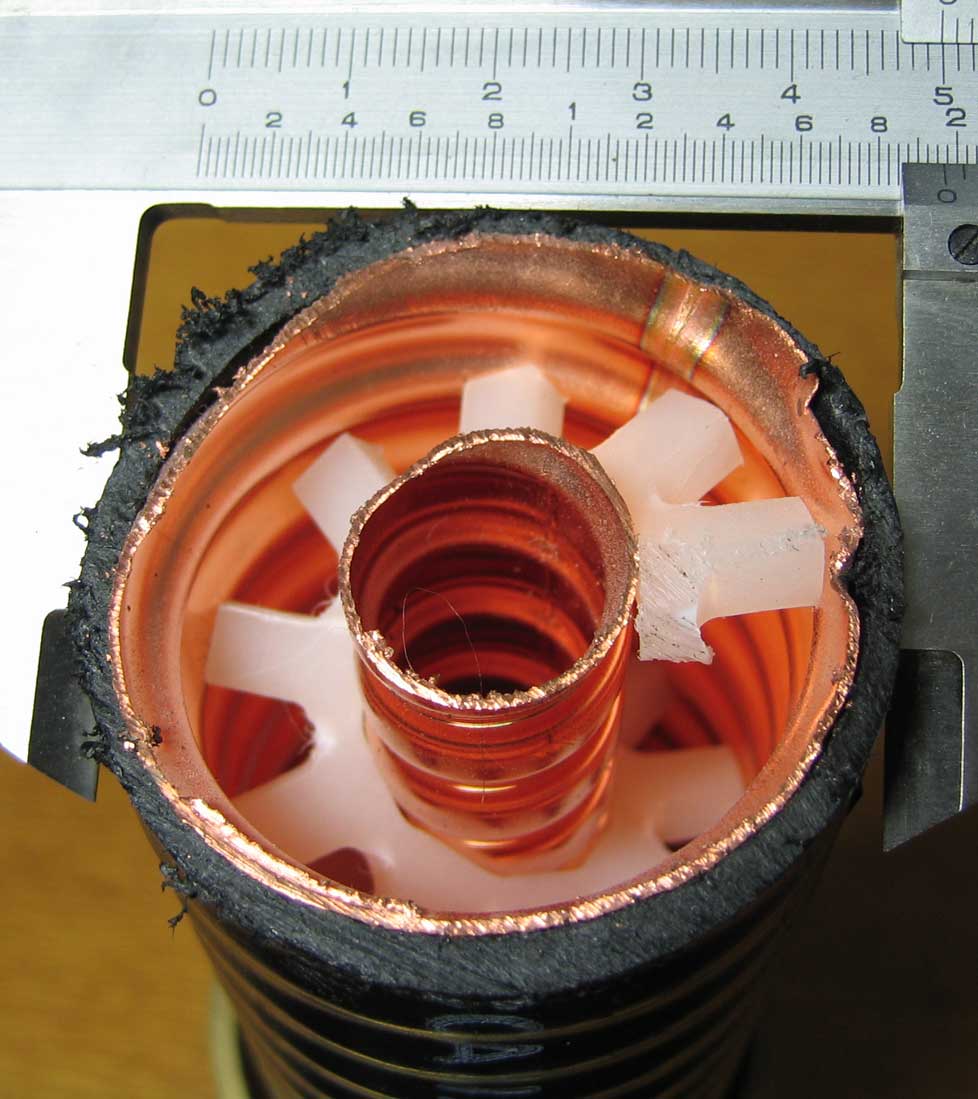
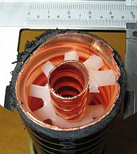 1-5/8" flexible line
Hard line is used in broadcasting as well as many other forms of radio communication. It is a coaxial cable constructed using round copper, silver or gold tubing or a combination of such metals as a shield. Some lower quality hard line may use aluminum shielding, aluminum however is easily oxidized and unlike silver or gold oxide, aluminum oxide drastically loses effective conductivity. Therefore all connections must be air and water tight. The center conductor may consist of solid copper, or copper plated aluminum. Since skin effect is an issue with RF, copper plating provides sufficient surface for an effective conductor. Most varieties of hardline used for external chassis or when exposed to the elements have a PVC jacket; however, some internal applications may omit the insulation jacket. Hard line can be very thick, typically at least a half inch or 13 mm and up to several times that, and has low loss even at high power. These large scale hard lines are almost always used in the connection between a transmitter on the ground and the antenna or aerial on a tower. Hard line may also be known by trademarked names such as Heliax (Andrew),[32] or Cablewave (RFS/Cablewave).[33] Larger varieties of hardline may consist of a center conductor which is constructed from either rigid or corrugated copper tubing. The dielectric in hard line may consist of polyethylene foam, air or a pressurized gas such as nitrogen or desiccated air (dried air). In gas-charged lines, hard plastics such as nylon are used as spacers to separate the inner and outer conductors. The addition of these gases into the dielectric space reduces moisture contamination, provides a stable dielectric constant, as well as a reduced risk of internal arcing. Gas-filled hardlines are usually used on high powered RF transmitters such as television or radio broadcasting, military transmitters, as well as high powered amateur radio applications but may also be used on some critical lower powered applications such as those in the microwave bands. Although in the microwave region waveguide is more often used than hard line for transmitter to antenna, or antenna to receiver applications. The various shields used in hardline also differ; some forms use rigid tubing, or pipe, others may use a corrugated tubing which makes bending easier, as well as reduces kinking when the cable is bent to conform. Smaller varieties of hard line may be used internally in some high frequency applications, particularly in equipment within the microwave range, to reduce interference between stages of the device.
Radiating
Main article: Leaky feederRadiating or Leaky Cable is another form of coaxial cable which is constructed in a similar fashion to hard line, however it is constructed with tuned slots cut into the shield. These slots are tuned to the specific RF wavelength of operation or tuned to a specific radio frequency band. This type of cable is to provide a tuned bi-directional "desired" leakage effect between transmitter and receiver. It is often used in elevator shafts, underground, transportation tunnels and in other areas where an antenna is not feasible. One example of this type of cable is Radiax (Andrew).[34]
RG-6
Main article: RG-6RG-6 is available in four different types designed for various applications. "Plain" or "house" wire is designed for indoor or external house wiring. "Flooded" cable is infused with heavy waterproofing for use in underground conduit (ideally) or direct burial. "Messenger" may contain some waterproofing but is distinguished by the addition of a steel messenger wire along its length to carry the tension involved in an aerial drop from a utility pole. "Plenum" wire comes with a special Teflon outer jacket designed for use in ventilation ducts to meet fire codes.
Triaxial cable
Main article: Triaxial cableTriaxial cable or triax is coaxial cable with a third layer of shielding, insulation and sheathing. The outer shield, which is earthed (grounded), protects the inner shield from electromagnetic interference from outside sources.
Twin-axial cable
Main article: Twinaxial cablingTwin-axial cable or twinax is a balanced, twisted pair within a cylindrical shield. It allows a nearly perfect differential signal which is both shielded and balanced to pass through. Multi-conductor coaxial cable is also sometimes used.
Biaxial cable
Main article: Twin-leadBiaxial cable, biax or Twin-Lead is a figure-8 configuration of two 50 Ω coaxial cables, externally resembling that of lamp cord, or speaker wire. Biax is used in some proprietary computer networks. Others may be familiar with 75Ω biax which at one time was popular on many cable TV services.
Semi-rigid
Semi-rigid cable is a coaxial form using a solid copper outer sheath. This type of coax offers superior screening compared to cables with a braided outer conductor, especially at higher frequencies. The major disadvantage is that the cable, as its name implies, is not very flexible, and is not intended to be flexed after initial forming. (See "hard line")
Conformable cable is a flexible reformable alternative to semi-rigid coaxial cable used where flexibility is required. Conformable cable can be stripped and formed by hand withouth the need for specialist tools, similar to standard coaxial cable.
Rigid line
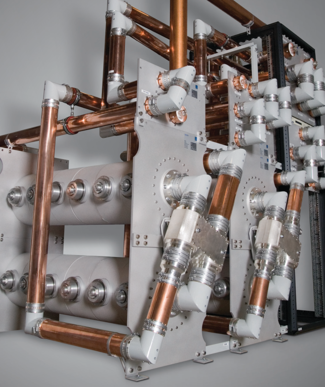
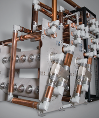 Rigid line
Rigid line is a coaxial formed by two copper tubes supported every other meter using PTFE-supports. Rigid lines are not possible to bend, so they often need elbows. Interconnection with rigid line is done with an inner bullet/inner support and a flange or connection kit. Rigid line is mainly used indoors for interconnection between transmitter and other RF-components, but even more rigid rigid line with flanges is used outdoors in antenna masts etc. With a flange connector it is possible to go from rigid line to hard line. Many broadcasting antennas and antenna splitters uses the flanged rigid line interface even when connecting to flexible coaxial cables and hard line.
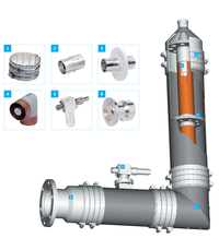 Rigid line parts
Rigid line is produced in a number of different sizes:
Outer conductor Inner conductor Size Outer diameter (not flanged) Inner diameter Outer diameter Inner diameter 7/8" 22.2 mm 20 mm 8.7 mm 7.4 mm 1 5/8" 41.3 mm 38.8 mm 16.9 mm 15.0 mm 3 1/8" 79.4 mm 76.9 mm 33.4 mm 42.6 mm 4 1/2" 106 mm 103 mm 44.8 mm 42.8 mm 6 1/8" 155.6 mm 151.9 mm 66.0 mm 64.0 mm Interference and troubleshooting
Coaxial cable insulation may degrade, requiring replacement of the cable, especially if it has been exposed to the elements on a continuous basis. The shield is normally grounded, and if even a single thread of the braid or filament of foil touches the center conductor, the signal will be shorted causing significant or total signal loss. This most often occurs at improperly installed end connectors and splices. Also, the connector or splice must be properly attached to the shield, as this provides the path to ground for the interfering signal.
Despite being shielded, interference can occur on coaxial cable lines. Susceptibility to interference has little relationship to broad cable type designations (e.g. RG-59, RG-6) but is strongly related to the composition and configuration of the cable's shielding. For cable television, with frequencies extending well into the UHF range, a foil shield is normally provided, and will provide total coverage as well as high effectiveness against high-frequency interference. Foil shielding is ordinarily accompanied by a tinned copper or aluminum braid shield, with anywhere from 60 to 95% coverage. The braid is important to shield effectiveness because (1) it is more effective than foil at absorbing low-frequency interference, (2) it provides higher conductivity to ground than foil, and (3) it makes attaching a connector easier and more reliable. "Quad-shield" cable, using two low-coverage aluminum braid shields and two layers of foil, is often used in situations involving troublesome interference, but is less effective than a single layer of foil and single high-coverage copper braid shield such as is found on broadcast-quality precision video cable.
In the United States and some other countries, cable television distribution systems use extensive networks of outdoor coaxial cable, often with in-line distribution amplifiers. Leakage of signals into and out of cable TV systems can cause interference to cable subscribers and to over-the-air radio services using the same frequencies as those of the cable system.
History
- 1880 — Coaxial cable patented in England by Oliver Heaviside, patent no. 1,407.[35]
- 1884 — Siemens & Halske patent coaxial cable in Germany (Patent No. 28,978, 27 March 1884).[36]
- 1894 — Oliver Lodge demonstrates waveguide transmission at the Royal Institution.
- 1929 — First modern coaxial cable patented by Lloyd Espenschied and Herman Affel of AT&T's Bell Telephone Laboratories.[37]
- 1936 — First closed circuit transmission of TV pictures on coaxial cable, from the 1936 Summer Olympics in Berlin to Leipzig.[38]
- 1936 — World's first underwater coaxial cable installed between Apollo Bay, near Melbourne, Australia, and Stanley, Tasmania. The 300 km cable can carry one 8.5-kHz broadcast channel and seven telephone channels.[39]
- 1936 — AT&T installs experimental coaxial telephone and television cable between New York and Philadelphia, with automatic booster stations every ten miles. Completed in December, it can transmit 240 telephone calls simultaneously.[40][41]
- 1936 — Coaxial cable laid by the General Post Office (now BT) between London and Birmingham, providing 40 telephone channels.[42][43]
- 1941 — First commercial use in USA by AT&T, between Minneapolis, Minnesota and Stevens Point, Wisconsin. L1 system with capacity of one TV channel or 480 telephone circuits.
- 1956 — First transatlantic coaxial cable laid, TAT-1.[44][45]
See also
- transmission line
- Radio frequency power transmission
- L-carrier
- Balanced pair
- Data cable
- Shielded cable
- Cable
- Category 5 cable
References
- ^ Nahin, Paul J. (2002). Oliver Heaviside: The Life, Work, and Times of an Electrical Genius of the Victorian Age. ISBN 0801869099.
- ^ a b H. Ward Silver, N0AX, and Mark J. Wilson, K1RO, ed (2010). "Chapter 20: Transmission Lines". The ARRL Handbook for Radio Communications (87th ed.). The American Radio Relay League. ISBN 0-87259-144-1.
- ^ Martin J. Van Der Burgt. "Coaxial Cables and Applications". Belden. p. 4. http://www.belden.com/pdfs/Techpprs/CoaxialCablesandApplications.pdf. Retrieved 11 July 2011.
- ^ a b c d e The ARRL UHF/MIcrowave Experimenter's Manual, American Radio Relay League, Newingont CT USA,1990 ISBN 0-87259-312-6, Chapter 5 Transmission Media pages 5.19 through 5.21
- ^ Jackson, John David (1962). Classical Electrodynamics. New York: John Wiley & Sons, Inc.. p. 244.
- ^ Pozar, David M. (1993). Microwave Engineering Addison-Wesley Publishing Company. ISBN 0-201-50418-9.
- ^ Elmore, William C.; Heald, Mark A. (1969). Physics of Waves. ISBN 0486649261.
- ^ Ott, Henry W. (1976). Noise Reduction Techniques in Electronic Systems. ISBN 0471657263.
- ^ Kizer, George Maurice (1990). Microwave communication. Iowa State University Press. p. 312. ISBN 9780813800264. http://books.google.co.uk/books?id=T2fI766k2R0C&pg=PA312.
- ^ http://www.rfcafe.com/references/electrical/coax.htm
- ^ See "field enhancement" discussion at http://www.microwaves101.com/encyclopedia/why50ohms.cfm
- ^ Microwaves 101: Why 50 Ohms?
- ^ Microwaves 101: Coax power handling
- ^ "Coaxial Cable Specifications for RG-62". http://www.madaboutcable.com/cables/coaxial_cables/products/rg6_coaxial_cable.html.
- ^ a b c d e f g h i j k l m n o p q r s t "Times Microwave Coax Loss Calculator". http://www.timesmicrowave.com/cgi-bin/calculate.pl. Retrieved 2011-10-26.
- ^ http://www.dxengineering.com/pdf/Belden%20RG8X%20Date%209258.pdf
- ^ "Coaxial Cable Specifications for RG-11". http://www.madaboutcable.com/cables/coaxial_cables/products/rg11_coaxial_cable.html.
- ^ "Coaxial Cable Specifications for RG-58". http://www.madaboutcable.com/cables/coaxial_cables/products/rg58_coaxial_cable.html.
- ^ "Coaxial Cable Specifications for RG-59". http://www.madaboutcable.com/cables/coaxial_cables/products/rg59_coaxial_cable.html.
- ^ "Coaxial Cable Specifications for RG-62". http://www.madaboutcable.com/cables/coaxial_cables/products/rg62_coaxial_cable.html.
- ^ "Coaxial Cable Specifications for RG-178". http://www.madaboutcable.com/cables/coaxial_cables/products/rg178_milspec_coaxial_cable.html.
- ^ Caledonian.com - RG178 Mini-Coax
- ^ "Coaxial Cable Specifications for 5 Core RG-179 (RGBHV)". http://www.madaboutcable.com/cables/audio_visual_cables/products/C07-R179AV5SL.html.
- ^ "Coaxial Cable Specifications for RG-213". http://www.madaboutcable.com/cables/coaxial_cables/products/rg213_coaxial_cable.html.
- ^ "Coaxial Cable Specifications for RG-214". http://www.madaboutcable.com/cables/coaxial_cables/products/rg214_coaxial_cable.html.
- ^ "Coaxial Cable Specifications for RG-316". http://www.madaboutcable.com/cables/coaxial_cables/products/rg316_coaxial_cable.html.
- ^ "Coaxial Cable Specifications for RG-400". http://www.madaboutcable.com/cables/coaxial_cables/products/rg400_coaxial_cable.html.
- ^ "Times Microwave LMR-240 Data Sheet". http://timesmicrowave.com/products/lmr/downloads/16-19.pdf. Retrieved 2011-10-26.
- ^ "Radio City Inc". http://www.radioinc.com/oscmax/catalog/product_info.php?name=LMR%20400%20UltraFlex%20(RG-8)%20100%20ft%20pre-cut&products_id=1121.
- ^ RF Cafe - Coaxial Cable Specifications Cables Chart
- ^ Microwaves 101 - Phase Velocity
- ^ "Andrew Heliax". http://www.commscope.com/andrew/eng/product/trans_line_sys/coaxial/wireless/1206774_13612.html.
- ^ "Cablewave Radio Frequency Systems (http://www.rfsworld.com)". http://www.rfsworld.com/.
- ^ "Andrew Radiax". http://www.commscope.com/andrew/eng/product/trans_line_sys/coaxial/radiating/1206639_13611.html.
- ^ Google Book Search - Oliver Heaviside By Paul J. Nahin
- ^ Feldenkirchen, Wilfried (1994). Werner von Siemens - Inventor and International Entrepreneur. ISBN 0814206581.
- ^ U.S. Patent 1,835,031
- ^ earlytelevision.org - Early Electronic Television - The 1936 Berlin Olympics
- ^ The worldwide history of telecommunications By Anton A. Huurdeman - Copper-Line Transmission
- ^ "Coaxial Debut," Time, Dec. 14, 1936.
- ^ Boing Boing - Gallery: An illustrated history of the transoceanic cable
- ^ Google books - Broadcast engineer's reference book By Edwin Paul J. Tozer
- ^ Radio-electronics.com - Coaxial feeder or RF coax cable
- ^ Atlantic-cable.com - 1956 TAT-1 Silver Commemorative Dish
- ^ Google books - The worldwide history of telecommunications By Anton A. Huurdeman
RF connectors (coaxial) APC-7 · BNC · C · F · FME · Hirose U.FL · IPX · Motorola · MCX · MMCX · N · QLS · QMA/QN · RCA · SMA · SMB · SMC · Twin-lead · TNC · TV aerial plug · UHF / Mini-UHF
Variations and alternate names: 2.9 mm (SMA) · 7 mm · Triax / Triaxial · Twin BNC / Twinax (BNC) · IPEX · MHF · AMC (UFL) · SnapN · RP-TNC · RP-SMA
Old or seldom used: EIA · GR · LEMO 00 · MusaSee also: Radio frequency · Radio spectrum · Audio and video connectors · Audio and video interfaces and connectorsCategories:- Signal cables
- Antennas (radio)
- Television terminology


Wikimedia Foundation. 2010.