- Impedance matching
-
In electronics, impedance matching is the practice of designing the input impedance of an electrical load (or the output impedance of its corresponding signal source) to maximize the power transfer and/or minimize reflections from the load.
 Source and load circuit impedance
In the case of a complex source impedance ZS and load impedance ZL, maximum power transfer is obtained when
where * indicates the complex conjugate. Minimum reflection is obtained when
The concept of impedance matching was originally developed for electrical power, but can be applied to any other field where a form of energy (not necessarily electrical) is transferred between a source and a load. An alternative to impedance matching is impedance bridging, where the load impedance is chosen to be much larger than the source impedance and maximizing voltage transfer (rather than power) is the goal.
Contents
Theory
Impedance is the opposition by a system to the flow of energy from a source. For constant signals, this impedance can also be constant. For varying signals, it usually changes with frequency. The energy involved can be electrical, mechanical, magnetic or thermal. The concept of electrical impedance is perhaps the most commonly known. Electrical impedance, like electrical resistance, is measured in ohms. In general, impedance has a complex value; this means that loads generally have a resistance to the source that is in phase with a sinusoidal source signal and reactance that is out of phase with a sinusoidal source signal. The total impedance (symbol: Z) is the vector sum of the resistance (symbol: R; a real number) and the reactance (symbol: X; an imaginary number).
In simple cases (such as low-frequency or direct-current power transmission) the reactance may be negligible or zero; the impedance can be considered a pure resistance, expressed as a real number. In the following summary we will consider the general case when resistance and reactance are both significant, and the special case in which the reactance is negligible.
Reflection-less (broadband) matching
Impedance matching to minimize reflections and maximize power transfer over a relatively large bandwidth (reflection-less or broadband matching) is the most commonly used. To prevent reflections of the signal back to the source, the load (which must be totally resistive) must be matched to the source impedance (which must also be totally resistive). In this case, if a transmission line is used to connect the source and load together, it must also be the same impedance: Zload = Zline = Zsource, where Zline is the characteristic impedance of the transmission line. Although source and load should each be totally resistive for this form of matching to work, the more-general term "impedance" is still used to describe the source and load characteristics. Any reactance present in the source or the load will affect the match.
Complex conjugate matching
This is used in cases in which the source and load are both reactive. This form of impedance matching can only maximize the power transfer between a reactive source and a reactive load at a single frequency. In this case,
- Zload = Zsource*
(where * indicates the complex conjugate).
If the signals are kept within the narrow frequency range for which the matching network was designed, reflections (in this narrow frequency band only) are also minimized. For the case of purely resistive source and load impedances, all reactance terms are zero and the formula above reduces to
- Zload = Zsource
as would be expected.
Power transfer
Main article: Maximum power theoremWhenever a source of power with a fixed output impedance such as an electric signal source, a radio transmitter or a mechanical sound (e.g., a loudspeaker) operates into a load, the maximum possible power is delivered to the load when the impedance of the load (load impedance or input impedance) is equal to the complex conjugate of the impedance of the source (that is, its internal impedance or output impedance). For two impedances to be complex conjugates their resistances must be equal, and their reactances must be equal in magnitude but of opposite signs. In low-frequency or DC systems (or systems with purely resistive sources and loads) the reactances are zero, or small enough to be ignored. In this case, maximum power transfer occurs when the resistance of the load is equal to the resistance of the source (see maximum power theorem for a mathematical proof).
Impedance matching is not always desirable. For example, if a source with a low impedance is connected to a load with a high impedance the power that can pass through the connection is limited by the higher impedance; however, the voltage transfer is higher and less prone to corruption than if the impedances had been matched. This maximum-voltage connection is a common configuration called impedance bridging or voltage bridging, and is widely used in signal processing. In such applications, delivering a high voltage (to minimize signal degradation during transmission and/or to consume less power by reducing currents) is often more important than maximum power transfer.
In older audio systems (reliant on transformers and passive filter networks, and based on the telephone system), the source and load resistances were matched at 600 ohms. One reason for this was to maximize power transfer, as there were no amplifiers available that could restore lost signal. Another reason was to ensure correct operation of the hybrid transformers used at central exchange equipment to separate outgoing from incoming speech, so these could be amplified or fed to a four-wire circuit. Most modern audio circuits, on the other hand, use active amplification and filtering and can use voltage-bridging connections for greatest accuracy. Strictly speaking, impedance matching only applies when both source and load devices are linear; however, matching may be obtained between nonlinear devices within certain operating ranges.
Impedance-matching devices
Adjusting the source impedance or the load impedance, in general, is called "impedance matching". There are three ways to improve an impedance mismatch, all of which are called "impedance matching":
- Devices intended to present an apparent load to the source of Rload = Rsource* (complex conjugate matching). Given a source with a fixed voltage and fixed source impedance, the maximum power theorem says this is the only way to extract the maximum power from the source.
- Devices intended to present an apparent load of Rload = Rline (complex impedance matching), to avoid echoes. Given a transmission line source with a fixed source impedance, this "reflectionless impedance matching" at the end of the transmission line is the only way to avoid reflecting echoes back to the transmission line.
- Devices intended to present an apparent source resistance as close to zero as possible, or presenting an apparent source voltage as high as possible. This is the only way to maximize energy efficiency, and so it is used at the beginning of electrical power lines. Such an impedance bridging connection also minimizes distortion and electromagnetic interference; it is also used in modern audio amplifiers and signal-processing devices.
There are a variety of devices used between a source of energy and a load that perform "impedance matching". To match electrical impedances, engineers use combinations of transformers, resistors, inductors, capacitors and transmission lines. These passive (and active) impedance-matching devices are optimized for different applications and include baluns, antenna tuners (sometimes called ATUs or roller-coasters, because of their appearance), acoustic horns, matching networks, and terminators.
Transformers
Transformers are sometimes used to match the impedances of circuits. A transformer converts alternating current at one voltage to the same waveform at another voltage. The power input to the transformer and output from the transformer is the same (except for conversion losses). The side with the lower voltage is at low impedance (because this has the lower number of turns), and the side with the higher voltage is at a higher impedance (as it has more turns in its coil).
One example of this method involves a television balun transformer. This transformer converts a balanced signal from the antenna (via 300-ohm twin-lead) into an unbalanced signal (75-ohm coaxial cable such as RG-6). To match the impedances of both devices, both cables must be connected to a matching transformer with a turns ratio of 2 (such as a 2:1 transformer). In this example, the 75-ohm cable is connected to the transformer side with fewer turns; the 300-ohm line is connected to the transformer side with more turns. The formula for calculating the transformer turns ratio for this example is Turns Ratio = √ [(Load Resistance)/(Source Resistance)].
Resistive network
Resistive impedance matches are easiest to design and can be achieved with a simple L pad consisting of two resistors. Power loss is an unavoidable consequence of using resistive networks, and they are only (usually) used to transfer line level signals.
Stepped transmission line
Most lumped-element devices can match a specific range of load impedances. For example, in order to match an inductive load into a real impedance, a capacitor needs be used. If the load impedance becomes capacitive, the matching element must be replaced by an inductor. In many cases, there is a need to use the same circuit to match a broad range of load impedance and thus simplify the circuit design. This issue was addressed by the stepped transmission line,[1] where multiple, serially placed, quarter-wave dielectric slugs are used to vary a transmission line's characteristic impedance. By controlling the position of each element, a broad range of load impedances can be matched without having to reconnect the circuit.
Some special situations (such as radio tuners and transmitters) use tuned filters such as stubs to match impedances at specific frequencies. These can distribute different frequencies to different places in the circuit. In addition, there is the closely related idea of power factor correction devices, intended to cancel the reactive and nonlinear characteristics of a load at the end of a power line. This causes the load seen by the power line to be purely resistive. For a given true power required by a load this minimizes the true current supplied through the power lines, and minimizes power wasted in the resistance of those power lines. For example, a maximum power point tracker is used to extract the maximum power from a solar panel and efficiently transfer it to batteries, the power grid or other loads. The maximum power theorem applies to its "upstream" connection to the solar panel, so it emulates a load resistance equal to the solar panel source resistance. However, the maximum power theorem does not apply to its "downstream" connection. That connection is an impedance bridging connection; it emulates a high-voltage, low-resistance source to maximize efficiency.
L-section
A simple electrical impedance-matching network requires one capacitor and one inductor. One reactance is in parallel with the source (or load), and the other is in series with the load (or source). If a reactance is in parallel with the source, the effective network matches from high to low impedance. The L-section is inherently a narrowband matching network.
The analysis is as follows. Consider a real source impedance of R1 and real load impedance of R2. If a reactance X1 is in parallel with the source impedance, the combined impedance can be written as:
If the imaginary part of the above impedance is canceled by the series reactance, the real part is
Solving for X1
If
 the above equation can be approximated as
The inverse connection (impedance step-up) is simply the reverse—for example, reactance in series with the source. The magnitude of the impedance ratio is limited by reactance losses such as the Q of the inductor. Multiple L-sections can be wired in cascade to achieve higher impedance ratios or greater bandwidth. Transmission line matching networks can be modeled as infinitely many L-sections wired in cascade. Optimal matching circuits can be designed for a particular system using Smith charts.
Transmission lines
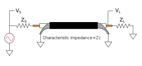 Coaxial transmission line with one source and one load
Impedance bridging is unsuitable for RF connections, because it causes power to be reflected back to the source from the boundary between the high and the low impedances. The reflection creates a standing wave if there is reflection at both ends of the transmission line, which leads to further power waste and may cause frequency-dependent loss. In these systems, impedance matching is desirable.
In electrical systems involving transmission lines (such as radio and fiber optics)—where the length of the line is long compared to the wavelength of the signal (the signal changes rapidly compared to the time it takes to travel from source to load)— the impedances at each end of the line must be matched to the transmission line's characteristic impedance (Zc) to prevent reflections of the signal at the ends of the line. (When the length of the line is short compared to the wavelength, impedance mismatch is the basis of transmission-line impedance transformers; see previous section.) In radio-frequency (RF) systems, a common value for source and load impedances is 50 ohms. A typical RF load is a quarter-wave ground plane antenna (37 ohms with an ideal ground plane; it can be matched to 50 ohms by using a modified ground plane or a coaxial matching section, i.e. part or all the feeder of higher impedance).
The general form of the voltage reflection coefficient for a wave moving from medium 1 to medium 2 is given by
while the voltage reflection coefficient for a wave moving from medium 2 to medium 1 is
so the reflection coefficient is the same (except for sign), no matter from which direction the wave approaches the boundary.
There is also a current reflection coefficient; it is the same as the voltage coefficient, except that it has an opposite sign. If the wave encounters an open at the load end, positive voltage and negative current pulses are transmitted back toward the source (negative current means the current is going the opposite direction). Thus, at each boundary there are four reflection coefficients (voltage and current on one side, and voltage and current on the other side). All four are the same, except that two are positive and two are negative. The voltage reflection coefficient and current reflection coefficient on the same side have opposite signs. Voltage reflection coefficients on opposite sides of the boundary have opposite signs.
Because they are all the same except for sign it is traditional to interpret the reflection coefficient as the voltage reflection coefficient (unless otherwise indicated). Either end (or both ends) of a transmission line can be a source or a load (or both), so there is no inherent preference for which side of the boundary is medium 1 and which side is medium 2. With a single transmission line it is customary to define the voltage reflection coefficient for a wave incident on the boundary from the transmission line side, regardless of whether a source or load is connected on the other side.
Single-source transmission line driving a load
Load-end conditions
In a transmission line, a wave travels from the source along the line. Suppose the wave hits a boundary (an abrupt change in impedance). Some of the wave is reflected back, while some keeps moving onwards. (Assume there is only one boundary, at the load.)
Let:
-
 and
and  be the voltage and current that is incident on the boundary from the source side.
 and
and  be the voltage and current that is transmitted to the load.
 and
and  be the voltage and current that is reflected back toward the source.
On the line side of the boundary
 and
and  and on the load side
  where , , , , , , and
  are phasors.
At a boundary, voltage and current must be continuous, therefore
All these conditions are satisfied by
where :
 the reflection coefficient going from the transmission line to the load.
The purpose of a transmission line is to get the maximum amount of energy to the other end of the line (or to transmit information with minimal error), so the reflection is as small as possible. This is achieved by matching the impedances ZL and Zc so that they are equal (Γ = 0).
Source-end conditions
At the source end of the transmission line, there may be waves incident both from the source and from the line; a reflection coefficient for each direction may be computed with
 , where Zs is the source impedance. The source of waves incident from the line are the reflections from the load end. If the source impedance matches the line, reflections from the load end will be absorbed at the source end. If the transmission line is not matched at both ends reflections from the load will be re-reflected at the source and re-re-reflected at the load end ad infinitum, losing energy on each transit of the transmission line. This can cause a resonance condition and strongly frequency-dependent behavior. In a narrow-band system this can be desirable for matching, but is generally undesirable in a wide-band system.
Source-end impedance
- where
 is the one-way transfer function (from either end to the other) when the transmission line is exactly matched at source and load.
  accounts for everything that happens to the signal in transit (including delay, attenuation and dispersion). If there is a perfect match at the load,
  and
and 
Transfer function
- where
 is the open circuit (or unloaded) output voltage from the source.
Note that if there is a perfect match at both ends
and  and then
Electrical examples
Telephone systems
Telephone systems also use matched impedances to minimise echo on long-distance lines. This is related to transmission-line theory. Matching also enables the telephone hybrid coil (2- to 4-wire conversion) to operate correctly. As the signals are sent and received on the same two-wire circuit to the central office (or exchange), cancellation is necessary at the telephone earpiece so excessive sidetone is not heard. All devices used in telephone signal paths are generally dependent on matched cable, source and load impedances. In the local loop, the impedance chosen is 600 ohms (nominal). Terminating networks are installed at the exchange to offer the best match to their subscriber lines. Each country has its own standard for these networks, but they are all designed to approximate about 600 ohms over the voice frequency band.
Loudspeaker amplifiers
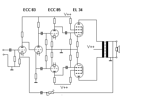
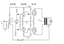 Typical push–pull audio tube power amplifier, matched to loudspeaker with an impedance-matching transformer
Audio amplifiers typically do not match impedances, but provide an output impedance that is lower than the load impedance (such as < 0.1 ohm in typical semiconductor amplifiers), for improved speaker damping. For vacuum tube amplifiers, impedance-changing transformers are often used to get a low output impedance, and to better match the amplifier's performance to the load impedance. Some tube amplifiers have output transformer taps to adapt the amplifier output to typical loudspeaker impedances.
The output transformer in vacuum-tube-based amplifiers has two basic functions:
- Separation of the AC component (which contains the audio signals) from the DC component (supplied by the power supply) in the anode circuit of a vacuum-tube-based power stage. A loudspeaker should not be subjected to DC current.
- Reducing the output impedance of power pentodes (such as the EL34) in a common-cathode configuration.
The impedance of the loudspeaker on the secondary coil of the transformer will be transformed to a higher impedance on the primary coil in the circuit of the power pentodes by the square of the turns ratio, which forms the impedance scaling factor.
The output stage in common-drain or common-collector semiconductor-based end stages with MOSFETs or power transistors has a very low output impedance. If they are properly balanced, there is no need for a transformer or a large electrolytic capacitor to separate AC from DC current.
Non-electrical examples
Acoustics
Similar to electrical transmission lines, an impedance matching problem exists when transferring sound energy from one medium to another. If the acoustic impedance of the two media are very different most sound energy will be reflected (or absorbed), rather than transferred across the border. The gel used in medical ultrasonography helps transfer acoustic energy from the transducer to the body and back again. Without the gel, the impedance mismatch in the transducer-to-air and the air-to-body discontinuity reflects almost all the energy, leaving very little to go into the body.
Horns are used like transformers, matching the impedance of the transducer to the impedance of the air. This principle is used in both horn loudspeakers and musical instruments. Most loudspeaker systems contain impedance matching mechanisms, especially for low frequencies. Because most driver impedances which are poorly matched to the impedance of free air at low frequencies (and because of out-of-phase cancellations between output from the front and rear of a speaker cone), loudspeaker enclosures both match impedances and prevent interference. Sound, coupling with air, from a loudspeaker is related to the ratio of the diameter of the speaker to the wavelength of the sound being reproduced. That is, larger speakers can produce lower frequencies at a higher level than smaller speakers for this reason. Elliptical speakers are a complex case, acting like large speakers lengthwise and small speakers crosswise. Acoustic impedance matching (or the lack of it) affects the operation of a megaphone, an echo and soundproofing.
Optics
A similar effect occurs when light (or any electromagnetic wave) hits the interface between two media with different refractive indices. For non-magnetic materials, the refractive index is inversely proportional to the material's characteristic impedance. An optical or wave impedance (that depends on the propagation direction) can be calculated for each medium, and may be used in the transmission-line reflection equation
to calculate reflection and transmission coefficients for the interface. For non-magnetic dielectrics, this equation is equivalent to the Fresnel equations. Unwanted reflections can be reduced by the use of an anti-reflection optical coating.
Mechanics
If a body of mass m collides elastically with a second body, maximum energy transfer to the second body will occur when the second body has the same mass m. In a head-on collision of equal masses, the energy of the first body will be completely transferred to the second body. In this case, the masses act as "mechanical impedances", which must be matched. If m1 and m2 are the masses of the moving and stationary bodies, and P is the momentum of the system (which remains constant throughout the collision), the energy of the second body after the collision will be E2:
which is analogous to the power-transfer equation in the above mathematical-proof section.
These principles are useful in the application of highly energetic materials (explosives). If an explosive charge is placed on a target, the sudden release of energy causes compression waves to propagate through the target radially from the point-charge contact. When the compression waves reach areas of high acoustic impedance mismatch (such as the opposite side of the target), tension waves reflect back and create spalling. The greater the mismatch, the greater the effect of creasing and spalling will be. A charge initiated against a wall with air behind it will do more damage to the wall than a charge initiated against a wall with soil behind it.
See also
- Maximum power theorem
- Power (physics)
- Reflection coefficient
- Ringing (signal)
- Standing wave ratio
- Transmission line
- Wet Transformer
Notes
- ^ Chunqui Qian and William W. Brey, "Impedance matching with an adjustable segmented transmission line". Journal of Magnetic Resonance, vol. 199 issue 1 (July 2009), pp. 104-110 Retrieved 2011-10-29.
- ^ Kraus (1984, p. 407)
- ^ Sadiku (1989, pp. 505–507)
- ^ Hayt (1989, pp. 398–401)
- ^ Karakash (1950, pp. 52–57)
References
- Hayt, William (1989), Engineering Electromagnetics (5th ed.), McGraw-Hill, ISBN 0070274061
- Karakash, John J. (1950), Transmission Lines and Filter Networks (1st ed.), Macmillan
- Kraus, John D. (1984), Electromagnetics (3rd ed.), McGraw-Hill, ISBN 0070354235
- Sadiku, Matthew N. O. (1989), Elements of Electromagnetics (1st ed.), Saunders College Publishing, ISBN 993013846
- Young, EC, The Penguin Dictionary of Electronics, Penguin, ISBN 0-14-051187-3 (see 'maximum power theorem', 'impedance matching')
- Floyd, Thomas (1997), Principles of Electric Circuits (5th ed.), Prentice Hall, ISBN 0132322242
External links
- Impedance Matching Impedance Matching with the Smith Chart for Antennas
- Unity Gain and Impedance Matching
- Impedance matching for microphones: Is it necessary? No.
- Calculation: Damping of impedance matching - connecting Zout and Zin
- Impedance matching: A primer
- Tutorial on RF impedance matching using the Smith Chart
- A description of impedance matching
- Conjugate matching versus reflectionless matching - pdf
- Impedance Matching Networks
- Java applets demonstrating impedance mismatching
- The impedance transformation along a stepped transmission line
Categories:- Electronic design
- Filter theory


Wikimedia Foundation. 2010.