- Micrometer
-
This article is about the measuring device. For the unit of length, see Micrometre.
 Outside, inside, and depth micrometers
A micrometer (
 /maɪˈkrɒmɨtər/ US dict: mī·krŏm′·ĭ·tər), sometimes known as a micrometer screw gauge, is a device incorporating a calibrated screw used widely for precise measurement of small distances in mechanical engineering and machining as well as most mechanical trades, along with other metrological instruments such as dial, vernier, and digital calipers. Micrometers are often, but not always, in the form of calipers.
Colloquially the word micrometer is often shortened to mike /ˈmaɪk/ (US dict: mīk′).
Contents
History of the device and its name
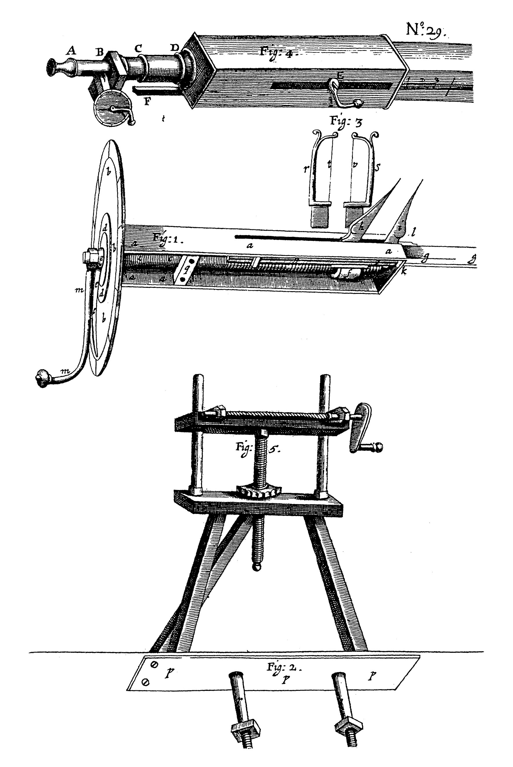
 Gascoigne's Micrometer as drawn by Robert Hooke
The word micrometer is a neoclassical coinage from Greek micros, "small", and metron, "measure". The Merriam-Webster Collegiate Dictionary[1] says that English got it from French and that its first known appearance in English writing was in 1670. Neither the metre nor the micrometre nor the micrometer (device) as we know them today existed at that time. However, humans of that time did have much need for, and interest in, the ability to measure small things, and small differences; the word no doubt was coined in reference to this endeavor, even if it did not refer specifically to its present-day senses.
The first ever micrometric screw was invented by William Gascoigne in the 17th century, as an enhancement of the vernier; it was used in a telescope to measure angular distances between stars.
Henry Maudslay built a bench micrometer in the early 19th century that was jocularly nicknamed "the Lord Chancellor" among his staff because it was the final judge on measurement accuracy and precision in the firm's work.
The first documented development of handheld micrometer-screw calipers was by Jean Laurent Palmer of Paris in 1848;[2] the device is therefore often called palmer in French, and tornillo de Palmer ("Palmer screw") in Spanish. (Those languages also use the micrometer cognates: micromètre, micrómetro.) The micrometer caliper was introduced to the mass market in anglophone countries by Brown & Sharpe in 1867,[3] allowing the penetration of the instrument's use into the average machine shop. Brown & Sharpe were inspired by several earlier devices, one of them being Palmer's design. In 1888 Edward Williams Morley added to the precision of micrometric measurements and proved their accuracy in a complex series of experiments.
The culture of toolroom accuracy and precision, which started with interchangeability pioneers including Gribeauval, Tousard, North, Hall, Whitney, and Colt, and continued through leaders such as Maudslay, Palmer, Whitworth, Brown, Sharpe, Pratt, Whitney, Leland, and others, grew during the Machine Age to become an important part of combining applied science with technology. Beginning in the early 20th century, one could no longer truly master tool and die making, machine tool building, or engineering without some knowledge of the science of metrology, as well as the sciences of chemistry and physics (for metallurgy, kinematics/dynamics, and quality).
Types
Basic types
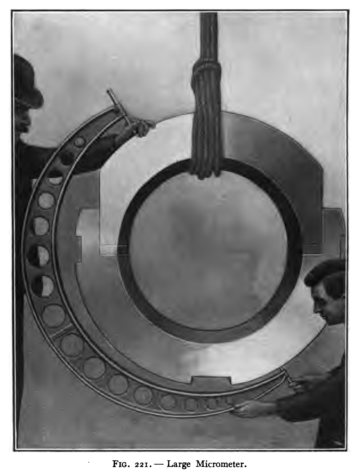
 Large micrometer caliper.
 Another large micrometer in use.
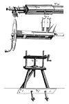
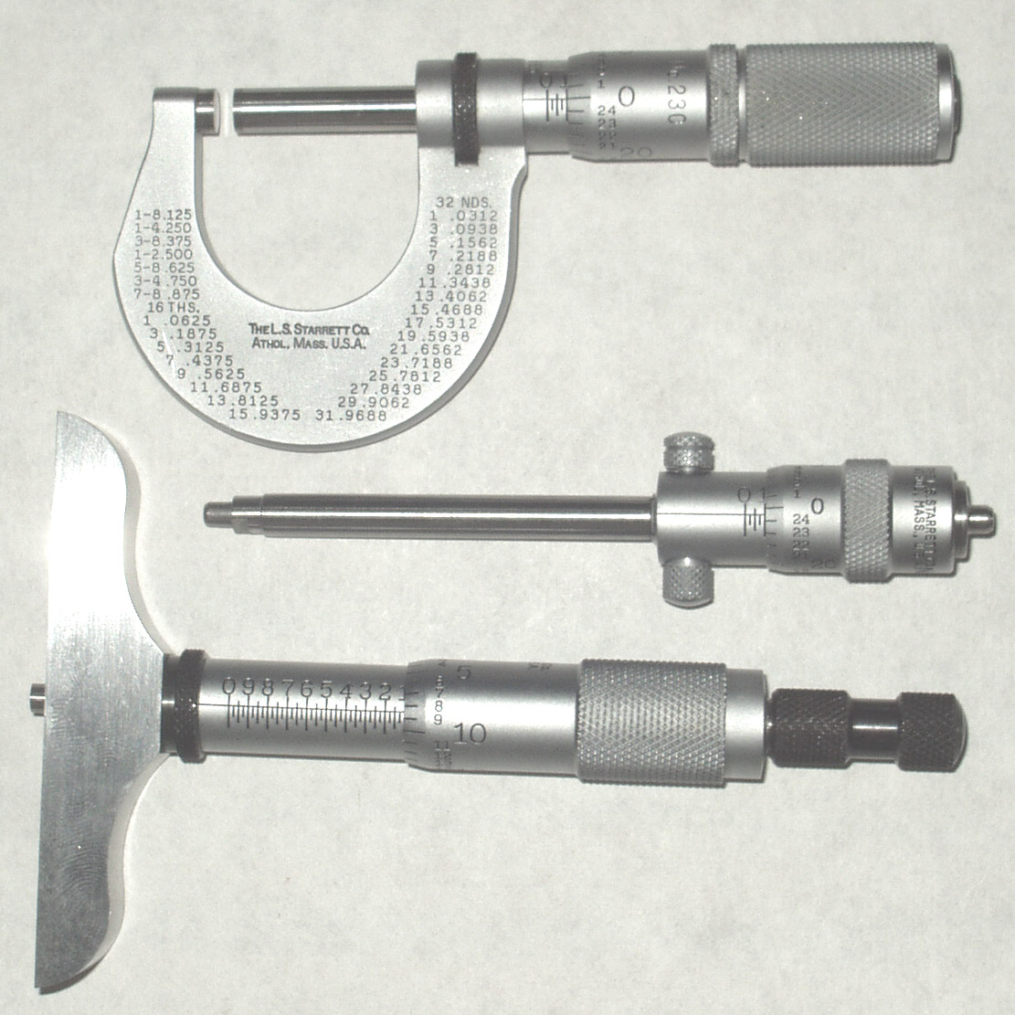
The topmost image shows the three most common types of micrometer; the names are based on their application:
- Outside micrometer (aka micrometer caliper), typically used to measure wires, spheres, shafts and blocks.
- Inside micrometer, used to measure the diameter of holes.
- Depth micrometer, measures depths of slots and steps.
Specialized types
Each type of micrometer caliper can be fitted with specialized anvils and spindle tips for particular measuring tasks. For example, the anvil may be shaped in the form of a segment of screw thread, in the form of a v-block, or in the form of a large disc.
- Universal micrometer sets come with interchangeable anvils, such as flat, spherical, spline, disk, blade, point, and knife-edge. The term universal micrometer may also refer to a type of micrometer whose frame has modular components, allowing one micrometer to function as outside mic, depth mic, step mic, etc. (often known by the brand names Mul-T-Anvil and Uni-Mike).
- Blade micrometers have a matching set of narrow tips (blades). They allow, for example, the measuring of a narrow o-ring groove.
- Pitch-diameter micrometers (aka thread mics) have a matching set of thread-shaped tips for measuring the pitch diameter of screw threads.
- Limit mics have two anvils and two spindles, and are used like a snap gauge. The part being checked must pass through the first gap and must stop at the second gap in order to be within specification. The two gaps accurately reflect the top and bottom of the tolerance range.
- Bore micrometer, typically a three-anvil head on a micrometer base used to accurately measure inside diameters.
- Tube micrometers have a cylindrical anvil positioned perpendicularly to a spindle and is used to measure the thickness of tubes.
- Micrometer stops micrometer heads that are mounted on the table of a manual milling machine, bedways of a lathe, or other machine tool, in place of simple stops. They help the operator to position the table or carriage precisely. Stops can also be used to actuate kickout mechanisms or limit switches to halt an automatic feed system.
- Ball micrometers have ball-shaped (spherical) anvils. They may have one flat and one ball anvil, in which case they are used for measuring tube wall thickness, distance of a hole to an edge, and other distances where one anvil must be placed against a rounded surface. They differ in application from tube micrometers in that they may be used to measure against rounded surfaces which are not tubes, but the ball anvil may also not be able to fit into smaller tubes as easily as a tube micrometer. Ball micrometers with a pair of balls can be used when single-tangential-point contact is desired on both sides. The most common example is in measuring the pitch diameter of screw threads (which is also done with conical anvils or the 3-wire method, the latter of which uses similar geometry as the pair-of-balls approach).
- Bench micrometers are tools for inspection use whose accuracy and precision are around half a micrometre (20 millionths of an inch, "a fifth of a tenth" in machinist jargon) and whose repeatability is around a quarter micrometre ("a tenth of a tenth"). An example is the Pratt & Whitney Supermicrometer brand.
- Digit mics are the type with mechanical digits that roll over.
- Digital mics are the type that uses an encoder to detect the distance and displays the result on a digital screen.
- V mics are outside mics with a small V-block for an anvil. They are useful for measuring the diameter of a circle from three points evenly spaced around it (versus the two points of a standard outside micrometer). An example of when this is necessary is measuring the diameter of 3-flute endmills and twist drills.
Operating principles
 animation of a micrometer used to measure an object(black) of length = 4.14 mm
Micrometers use the principle of a screw to amplify small distances that are too small to measure directly into large rotations of the screw that are big enough to read from a scale. The accuracy of a micrometer derives from the accuracy of the thread-form that is at its heart. The basic operating principles of a micrometer are as follows:
- The amount of rotation of an accurately made screw can be directly and precisely correlated to a certain amount of axial movement (and vice versa), through the constant known as the screw's lead (/ˈliːd/). A screw's lead is the distance it moves forward axially with one complete turn (360°). (In most threads [that is, in all single-start threads], lead and pitch refer to essentially the same concept.)
- With an appropriate lead and major diameter of the screw, a given amount of axial movement will be amplified in the resulting circumferential movement.
For example, if the lead of a screw is 1 mm, but the major diameter (here, outer diameter) is 10 mm, then the circumference of the screw is 10π, or about 31.4 mm. Therefore, an axial movement of 1 mm is amplified (magnified) to a circumferential movement of 31.4 mm. This amplification allows a small difference in the sizes of two similar measured objects to correlate to a larger difference in the position of a micrometer's thimble.
In older micrometers the position of the thimble is read directly from scale markings on the thimble and shaft. A vernier scale is usually included, which allows the position to be read to a fraction of the smallest scale mark. In newer digital micrometers, an electronic readout displays the length digitally on an LCD display on the instrument. There also exist mechanical-digit versions, like the style of car odometers where the numbers "roll over".
Parts
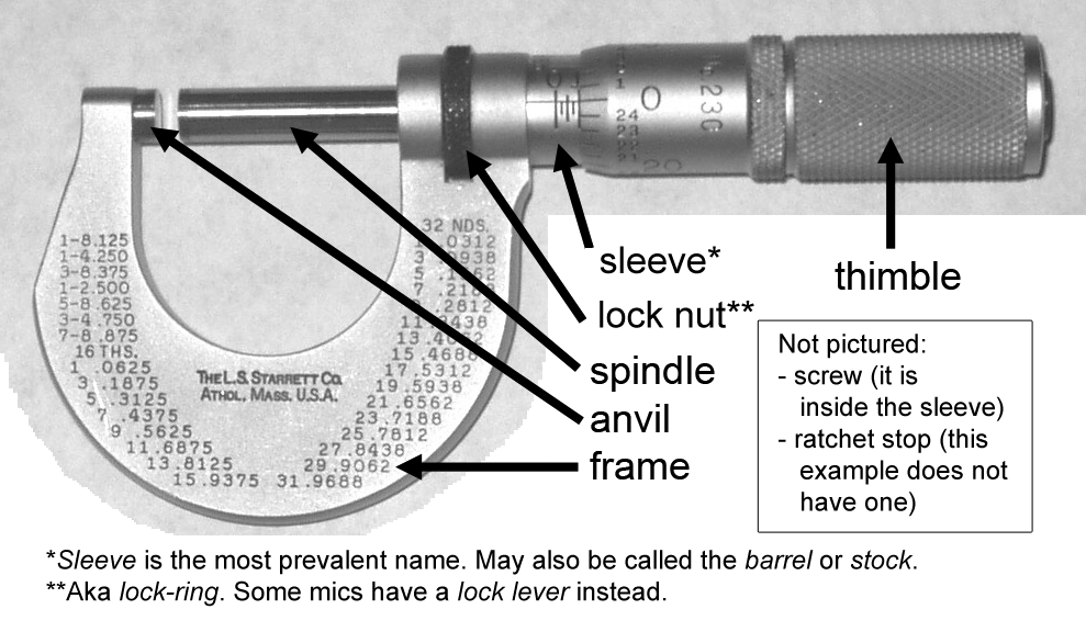
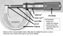 The parts of a micrometer caliper, labeled. (Notice also that there is a handy decimal-fraction equivalents chart printed right on the frame of this inch-reading micrometer.)
A micrometer is composed of:
- Frame
- The C-shaped body that holds the anvil and barrel in constant relation to each other. It is thick because it needs to minimize flexion, expansion, and contraction, which would distort the measurement.
The frame is heavy and consequently has a high thermal mass, to prevent substantial heating up by the holding hand/fingers. It is often covered by insulating plastic plates which further reduce heat transference.
Explanation: if you hold the frame long enough so that it heats up by 10°C, then the increase in length of any 10 cm linear piece of steel is of magnitude 1/100 mm. For micrometers this is their typical accuracy range.
Micrometers typically have a specified temperature at which the measurement is correct (often 20°C [68°F], which is generally considered "room temperature" in a room with HVAC). Toolrooms are generally kept at 20°C [68°F]. - Anvil
- The shiny part that the spindle moves toward, and that the sample rests against.
- Sleeve / barrel / stock
- The stationary round part with the linear scale on it. Sometimes vernier markings.
- Lock nut / lock-ring / thimble lock
- The knurled part (or lever) that one can tighten to hold the spindle stationary, such as when momentarily holding a measurement.
- Screw
- (not seen) The heart of the micrometer, as explained under "Operating principles". It is inside the barrel. (No wonder that the usual name for the device in German is Messschraube, literally "measuring screw".)
- Spindle
- The shiny cylindrical part that the thimble causes to move toward the anvil.
- Thimble
- The part that one's thumb turns. Graduated markings.
- Ratchet stop
- (not shown in illustration) Device on end of handle that limits applied pressure by slipping at a calibrated torque.
Reading
Inch system
 Micrometer thimble showing 0.276 inch
The spindle of an inch-system micrometer has 40 threads per inch, so that one turn moves the spindle axially 0.025 inch (1 ÷ 40 = 0.025), equal to the distance between two graduations on the frame. The 25 graduations on the thimble allow the 0.025 inch to be further divided, so that turning the thimble through one division moves the spindle axially 0.001 inch (0.025 ÷ 25 = 0.001). Thus, the reading is given by the number of whole divisions that are visible on the scale of the frame, multiplied by 25 (the number of thousandths of an inch that each division represents), plus the number of that division on the thimble which coincides with the axial zero line on the frame. The result will be the diameter expressed in thousandths of an inch. As the numbers 1, 2, 3, etc., appear below every fourth sub-division on the frame, indicating hundreds of thousandths, the reading can easily be taken mentally.
Suppose the thimble were screwed out so that graduation 2, and three additional sub-divisions, were visible (as shown in the image), and that graduation 1 on the thimble coincided with the axial line on the frame. The reading then would be 0.2000 + 0.075 + 0.001, or .276 inch.
Metric system
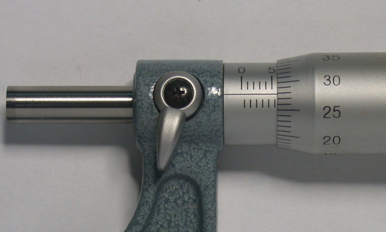
 Micrometer thimble reading 5.78mm
The spindle of an ordinary metric micrometer has 2 threads per millimetre, and thus one complete revolution moves the spindle through a distance of 0.5 millimetre. The longitudinal line on the frame is graduated with 1 millimetre divisions and 0.5 millimetre subdivisions. The thimble has 50 graduations, each being 0.01 millimetre (one-hundredth of a millimetre). Thus, the reading is given by the number of millimetre divisions visible on the scale of the sleeve plus the particular division on the thimble which coincides with the axial line on the sleeve.
Suppose that the thimble were screwed out so that graduation 5, and one additional 0.5 subdivision were visible (as shown in the image), and that graduation 28 on the thimble coincided with the axial line on the sleeve. The reading then would be 5.00 + 0.5 + 0.28 = 5.78 mm.
Vernier
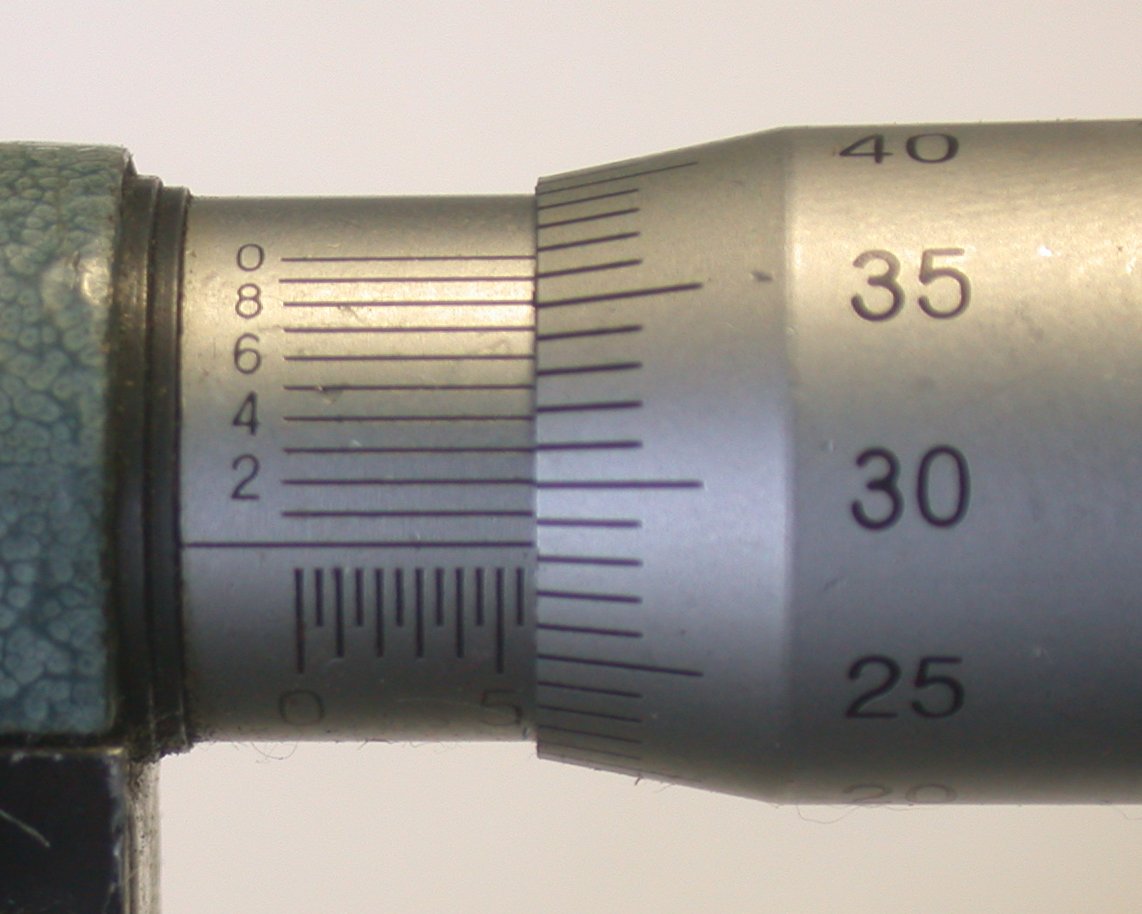
 Micrometer sleeve (with vernier) reading 5.783mm
Some micrometers are provided with a vernier scale on the sleeve in addition to the regular graduations. These permit measurements within 0.001 millimetre to be made on metric micrometers, or 0.0001 inches on inch-system micrometers.
The additional digit of these micrometers is obtained by finding the line on the sleeve vernier scale which exactly coincides with one on the thimble. The number of this coinciding vernier line represents the additional digit.
Thus, the reading for metric micrometers of this type is the number of whole millimetres (if any) and the number of hundredths of a millimetre, as with an ordinary micrometer, and the number of thousandths of a millimetre given by the coinciding vernier line on the sleeve vernier scale.
For example, a measurement of 5.783 millimetres would be obtained by reading 5.5 millimetres on the sleeve, and then adding 0.28 millimetre as determined by the thimble. The vernier would then be used to read the 0.003 (as shown in the image).
Inch micrometers are read in a similar fashion.
Note: 0.01 millimetre = 0.000393 inch, and 0.002 millimetre = 0.000078 inch (78 millionths) or alternatively, 0.0001 inch = 0.00254 millimetres. Therefore, metric micrometers provide smaller measuring increments than comparable inch unit micrometers—the smallest graduation of an ordinary inch reading micrometer is 0.001 inch; the vernier type has graduations down to 0.0001 inch (0.00254 mm). When using either a metric or inch micrometer, without a vernier, smaller readings than those graduated may of course be obtained by visual interpolation between graduations.
Torque repeatability via torque-limiting ratchets or sleeves
An additional feature of many micrometers is the inclusion of a torque-limiting device on the thimble—either a spring-loaded ratchet or a friction sleeve. Without this device, workers may overtighten the micrometer on the work, causing the mechanical advantage of the screw to squeeze the material or tighten the screw threads, giving an inaccurate measurement. However, with a thimble that will ratchet or friction slip at a certain torque, the micrometer will not continue to advance once sufficient resistance is encountered. This results in greater accuracy and repeatability of measurements—most especially for low-skilled or semi-skilled workers, who may not have developed the light, consistent touch of a skilled user.
Testing and calibration
A standard ordinary one-inch micrometer has readout divisions of .001 inch and a rated accuracy of +/- .0001 inch[4] ("one tenth", in machinist parlance). Both the measuring instrument and the object being measured should be at room temperature for an accurate measurement; dirt, abuse, and operator skill are the main sources of error.[5]
The accuracy of micrometers is checked by using them to measure gauge blocks, rods, or similar standards whose lengths are precisely and accurately known. If the gauge block is known to be 0.7500" ± .00005" ("seven-fifty plus or minus fifty millionths", that is, "seven hundred fifty thou plus or minus half a tenth"), then the micrometer should measure it as 0.7500". If the micrometer measures 0.7516", then it is out of calibration.
Calibration can also include the condition of the tips (flat and parallel), any ratchet, and linearity of the scale.[6] Calibration would record the error at approx 5 points along the scale. Only one can be adjusted to zero. Flatness and parallelism are typically measured with a gage called an optical flat, a disc of glass or plastic ground with extreme accuracy to have flat, parallel faces, which allows light bands to be counted when the micrometer's anvil and spindle are against it, revealing their amount of geometric inaccuracy.
Commercial machine shops, especially those that do certain categories of work (military or commercial aerospace, nuclear power industry, and others), are required by various standards organizations (such as ISO, ANSI, ASME, ASTM, SAE, AIA, the U.S. military, and others) to calibrate micrometers and other gages on a schedule (often annually), to affix a label to each gage that gives it an ID number and a calibration expiration date, to keep a record of all the gages by ID number, and to specify in inspection reports which gage was used for a particular measurement.
Not all calibration is an affair for metrology labs. A micrometer can be calibrated on-site anytime, at least in the most basic and important way (if not comprehensively), by measuring a high-grade gage block and adjusting to match. Even gages that are calibrated annually and within their expiration timeframe should be checked this way every month or two, if they are used daily. They usually will check out OK as needing no adjustment.
The accuracy of the gauge blocks themselves is traceable through a chain of comparisons back to a master standard such as the international prototype meter. This bar of metal, like the international prototype kilogram, is maintained under controlled conditions at the International Bureau of Weights and Measures headquarters in France, which is one of the principal measurement standards laboratories of the world. These master standards have extreme-accuracy regional copies (kept in the national laboratories of various countries, such as NIST), and metrological equipment makes the chain of comparisons. Because the definition of the meter is now based on a light wavelength, the international prototype meter is not quite as indispensable as it once was. But such master gauges are still important for calibrating and certifying metrological equipment. Equipment described as "NIST traceable" means that its comparison against master gages, and their comparison against others, can be traced back through a chain of documentation to equipment in the NIST labs. Maintaining this degree of traceability requires some expense, which is why NIST-traceable equipment is more expensive than non-NIST-traceable. But applications needing the highest degree of quality control mandate the cost.
Zero error
 the answer is =main scale + dial scale - (zero error) =4.00 + 0.29 - ( 0.15) = 4.14 mm
 the answer is =main scale + dial scale - (zero error) =4.00 + 0.05 - ( -0.09) = 4.14 mm
Zero error is the reading when the jaws are closed. It is the calibration error of the device - often caused by knocks or overstrains.
The way to use a micrometer with zero error is to use the formula 'actual reading = main scale + micro scale - (zero error)'.
Positive zero error refers to the fact that when the jaws of the micrometer are just closed, the reading is a positive reading away from the actual reading of 0.00mm. If the reading is 0.15mm, the zero error is referred to as +0.15mm.
Negative zero error refers to the fact that when the jaws of the micrometer are just closed, the reading is a negative reading away from the actual reading of 0.00mm. If the reading is -0.09mm, the zero error is referred to as -0.09mm.
See also
References
- ^ Merriam-Webster. "Merriam-Webster Online Dictionary (based on M-W Collegiate Dictionary).". Merriam-Webster. http://m-w.com/dictionary/micrometer. Retrieved 2007-11-14.
- ^ Roe 1916:212.
- ^ Roe 1916:210-213, 215.
- ^ http://www.starrett.com/download/222_p1_5.pdf GENERAL MICROMETER INFORMATION
- ^ http://www.mahr.de/index.php?NodeID=13120 MICROMETER ACCURACY: Drunken Threads and Slip-sticks
- ^ http://ittc.sname.org/2006_recomm_proc/7.6-02-04.res.pdf ITTC – Recommended Procedures : Sample Work Instructions Calibration of Micrometers.
Bibliography
- Roe, Joseph Wickham (1916), English and American Tool Builders, New Haven, Connecticut, USA: Yale University Press, LCCN 16-011753, http://books.google.com/books?id=X-EJAAAAIAAJ&printsec=titlepage. Reprinted by McGraw-Hill, New York and London, 1926 (LCCN 27-024075); and by Lindsay Publications, Inc., Bradley, IL, USA (ISBN 978-0-917914-73-7).
External links
- Simulator to practice reading and interpreting one-hundredth of a millimetre outside micrometer
- Simulator to practice reading and interpreting one-thousandth of a millimetre outside micrometer
- Print files including lessons and quizzes for teachers and students of the subject matter.
- Simulator to practice reading and interpreting one-thousandth of an inch outside micrometer
- Simulator to practice reading and interpreting ten-thousandth of an inch outside micrometer
- Quantum Laser Micrometers
Types of tools Cleaning tools Broom · Brush · Feather duster · Floor buffer · Hataki · Ice resurfacer · Mop · Mop bucket cart · Office cleaning cart · Pipe cleaner · Pressure washer · Sponge · Squeegee · Steam mop · Tawashi · Vacuum cleanerCutting and
abrasive toolsBlade · Bolt cutter · Broach · Ceramic tile cutter · Chisel · Coping saw · Countersink · Diamond blade · Diamond tool · Draw knife · Drill bit · Emery cloth · File · Fretsaw · Froe · Glass cutter · Grater · Grinding wheel · Hand saw · Knife · Miter saw · Nail clipper · Pipecutter · Plane · Rasp · Razor · Reamer · Sandpaper · Saw · Scalpel · Scissors · Steel wool · Surform · Switchblade · Utility knife · Water jet cutter · Wire brush · Wire cutter · Wire stripperGarden tools Adze · Axe · Billhook · Bow saw · Chainsaw · Cultivator · Earth auger · Edger · Garden fork · Garden hose · Garden trowel · Hatchet · Hedge trimmer · Hoe · Hori hori · Irrigation sprinkler · Lawn aerator · Lawn mower · Lawn sweeper · Leaf blower · Loppers · Loy · Machete · Mattock · Pickaxe · Pitchfork · Plough (plow) · Post hole digger · Pruning shears (secateurs) · Rake · Roller · Rotary tiller · Scythe · Shovel · Sickle · Slasher · Spade · Splitting maul · String trimmerHand tools Block plane · BNC inserter/remover · Brace · Bradawl · Breaker bar · Card scraper · Cat's paw · Caulking gun · Clamp · Crimping pliers · Crowbar · Grease gun · Fish tape · Hammer · Hand truck · Hawk · Hex key · Jack · Lug wrench · Locking pliers · Mallet · Mitre box · Monkey wrench · Nut driver · Paint roller · Paintbrush · Pipe wrench · Pliers · Plumber's snake · Plunger · Punch · Punch down tool · Putty knife · Ratchet · Sink wrench · Scratch awl · Screwdriver · Sledgehammer · Socket wrench · Spike maul · Staple gun · Stitching awl · Strap wrench · Tire iron · Torque wrench · Trowel · Upholstery hammer · Wrench (spanner)Machine and
metalworking toolsAutomatic lathe · Ball-peen hammer · Broaching machine · Drill press · Endmill · English wheel · Gear shaper · Grinding machine · Hacksaw · Hobbing machine · Jig borer · Lathe · Metalworking lathe · Milling cutter · Milling machine · Planer · Plasma cutter · Screw machine · Shaper · Tap and die · Thread restorer · Tool bit · Turret lathe · WelderMeasuring and
alignment toolsArchitect's scale · Beam compass · Caliper · Chalk box · Compass · Engineer's scale · Flexible curve · Jig · Laser level · Laser line level · Laser measuring tool · Micrometer · Plumb-bob · Protractor · Ruler · Scale · Sliding T bevel · Spirit level · Square · Straightedge · Tape measure · TemplatePower tools Angle grinder · Bandsaw · Belt sander · Blow torch · Chop saw · Circular saw · Concrete saw · Crusher · Cutting torch · Die grinder · Drill · Glue gun · Heat gun · Impact wrench · Jackhammer · Jigsaw · Jointer · Nail gun · Needlegun scaler · Power trowel · Radial arm saw · Random orbital sander · Reciprocating saw · Rotary tool · Router table · Sander · Scroll saw · Soldering gun · Soldering iron · Steam box · Table saw · Thickness planer · Wood router · Wood shaperOther Antique tools · Backscratcher · Bucket · Comb · Flashlight · Halligan bar · Kelly tool · Ladder · Pencil · Toolbox · Vise · WorkbenchCategories:- Dimensional instruments
- Metalworking measuring instruments


Wikimedia Foundation. 2010.