- Machine taper
-
A machine taper is a system for securing cutting bits and other accessories to a machine tool's spindle.
Contents
Explanation
Machine tool operators must be able to install or remove tool bits quickly and easily. A lathe, for example, has a rotating spindle in its headstock, to which one may want to mount a spur drive or work in a collet. Another example is a drill press, to which an operator may want to mount a bit directly, or using a drill chuck.
Virtually all milling machines, from the oldest, manual machines up to the most modern CNC machines utilize tooling that is piloted on a tapered surface.
The machine taper is a simple, low-cost, highly repeatable, and versatile tool mounting system that uses tool bits (or holders) with gradually tapered shanks, and a matching hollowed-out spindle.
For light loads (such as encountered by a lathe tailstock), tools are simply slipped onto or into the spindle; the pressure of the spindle against the workpiece drives the tapered shank tightly into the tapered hole. The friction across the entire surface area of the interface provides a large amount of torque transmission, so that splines or keys are not required.
For heavy loads (such as encountered by a milling machine spindle), the tapered shank of the tool (or collet) is threaded, and often has a key. Commonly, there is a threaded hole in the shank, which is engaged by a matching drawbar. The drawbar is then tightened, drawing the shank firmly into the spindle.
Use
Tools with a tapered shank are inserted into a matching tapered socket and pushed or twisted into place. They are then retained by friction. In some cases, the friction fit needs to be made stronger, as with the use of a drawbar, essentially a long bolt that holds the tool into the socket with more force than is possible by other means.
Tapered shanks "stick" in a socket best when both the shank and the socket are clean. Shanks can be wiped clean, but sockets, being deep and inaccessible, are best cleaned with a specialized taper cleaning tool which is inserted, twisted, and removed.
Tapered shank tools are removed from a socket using different approaches, depending on the design of the socket. In drill presses and similar tools, the tool is removed by inserting a wedge shaped block of metal called a "drift" into a rectangular shaped cross hole through the socket and tapping it. As the cross section of the drift gets larger when the drift is driven further in, the result is that the drift, bearing against the foremost edge of the tang, pushes the tool out. In many lathe tailstocks, the tool is removed by fully withdrawing the quill into the tailstock, which brings the tool up against the end of the leadscrew or an internal stud, separating the taper and releasing the tool. Where the tool is retained by a drawbar, as in some mill spindles, the drawbar is partially unthreaded with a wrench and then tapped with a hammer, which separates the taper, at which point the tool can be further unthreaded and removed. For simple sockets with open access to the back end, a drift punch is inserted axially from behind and the tool tapped out.
Types
There are multiple standard tapers, which differing based on the following:
- the diameter at the small end of the truncated cone ("the minor diameter")
- the diameter at the large end of the truncated cone ("the major diameter") and
- the axial distance between the two ends of the truncated cone.
The standards are grouped into families. Though a family of tapers could be designed that all taper at the same angle, existing families all differ.
One of the first uses of tapers was to mount drill bits directly to machine tools, such as in the tailstock of a lathe, although later drill chucks were invented that mounted to machine tools and in turn held non-tapered drill bits.
Morse
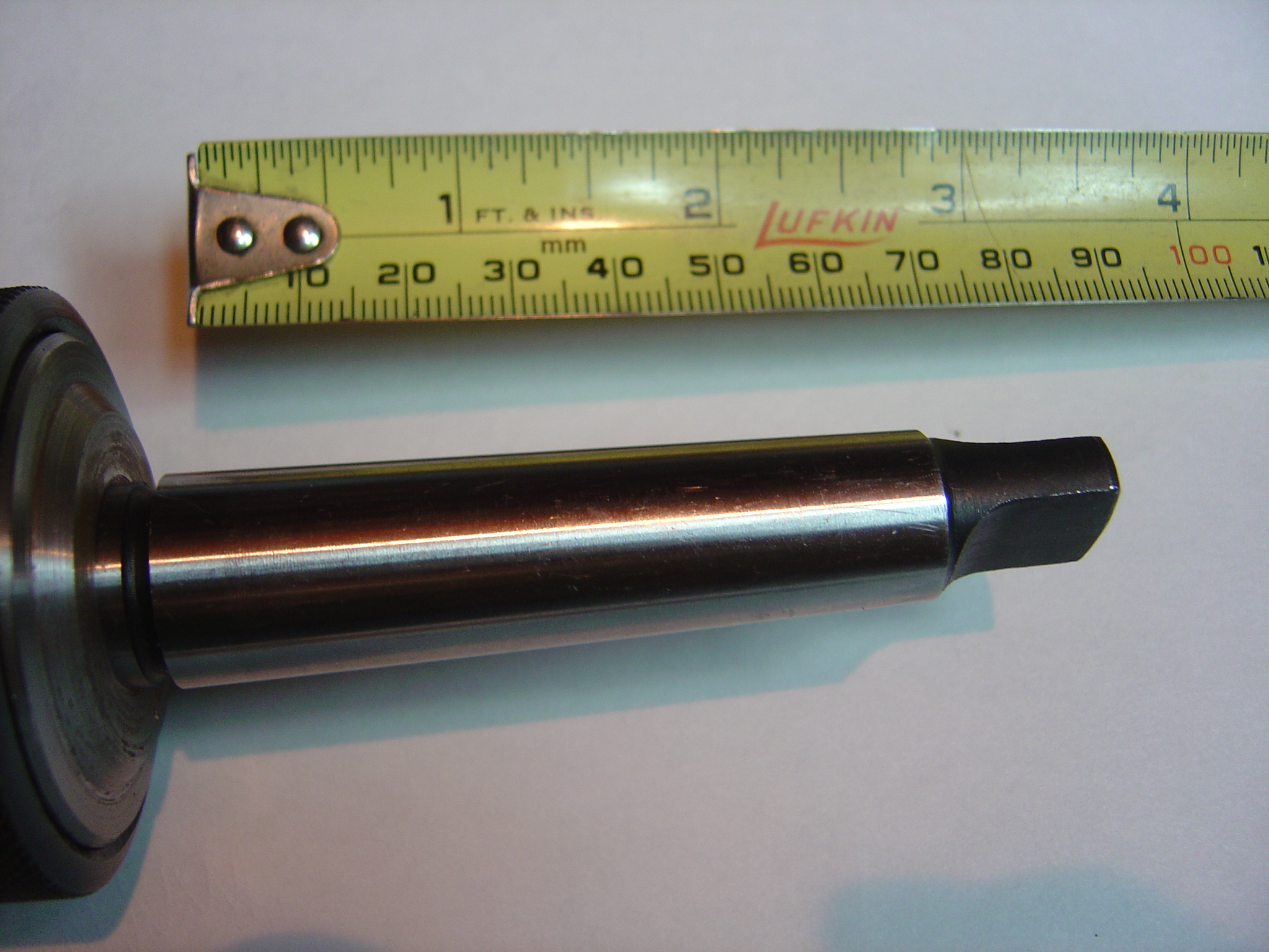
 Morse Taper #2 (MT2)
The Morse Taper was invented by Stephen A. Morse in the mid-1860s.[1] Since then, it has evolved to encompass smaller and larger sizes and has been adopted as a standard by numerous organizations, including the International Organization for Standardization (ISO) as ISO 296 and the German Institute for Standardization (DIN) as DIN 228-1. It is one of the most widely used types, and is particularly common on the shank of taper-shank twist drills and machine reamers, in the spindles of industrial drill presses, and in the tailstocks of lathes.[citation needed]
Sizes
Morse Tapers come in eight sizes identified by whole numbers between 0 and 7, and one half-size (4 1/2 - very rarely found, and not shown in the table). Often the designation is abbreviated as MT followed by a digit, for example a Morse taper number 4 would be MT4. The MT2 taper is the size most often found in drill presses up to ½" capacity. Stub (short) versions, the same taper angle but a little over half the usual length, are occasionally encountered for the whole number sizes from 1 through 5. There are standards for these, which (inter alia) are sometimes used in lathe headstocks to preserve a larger spindle through-hole.
End types
Morse tapers are of the self-holding variety, and can have three types of ends:
- tang (illustrated) to facilitate removal with a drift
- threaded to be held in place with a drawbar
- flat (no tang or threaded section)
Self holding tapers rely on a heavy preponderance of axial load over radial load to transmit high torques. Problems may arise using large drills in relation to the shank, if the pilot hole is too large. The threaded style is essential for any sideloading, particularly milling. The only exception is that such unfavourable situations can be simulated to remove a jammed shank. Permitting chatter will help release the grip. The acute (narrow) taper angle can result in such jamming with heavy axial loads, or over long periods.
End-Milling cutters with a Morse taper shank with a tang are occasionally seen: for security these must be used with a C-collar or similar, fitting into the neck between cutter and shank, and pulling back against the large end of the taper
The taper itself is roughly 5/8" per foot, but exact ratios and dimensions for the various sizes of tang type tapers are given below.
Dimensions

Morse Taper dimensions (mm) Morse Taper number Taper A B (max) C (max) D (max) E (max) F G H J K 0 1:19.212 9.045 56.5 59.5 10.5 6 4 1 3 3.9 1° 29' 27" 1 1:20.047 12.065 62 65.5 13.5 8.7 5 1.2 3.5 5.2 1° 25' 43" 2 1:20.020 17.780 75 80 16 13.5 6 1.6 5 6.3 1° 25' 50" 3 1:19.922 23.825 94 99 20 18.5 7 2 5 7.9 1° 26' 16" 4 1:19.254 31.267 117.5 124 24 24.5 8 2.5 6.5 11.9 1° 29' 15" 5 1:19.002 44.399 149.5 156 29 35.7 10 3 6.5 15.9 1° 30' 26" 6 1:19.180 63.348 210 218 40 51 13 4 8 19 1° 29' 36" 7 1:19.231 83.058 285.75 294.1 34.9 - - 19.05 - 19 1° 29' 22" Brown & Sharpe
Brown & Sharpe tapers, standardized by the eponymous company, are an alternative to the more-commonly seen Morse taper. Like the Morse, these have a series of sizes, from 1 to 18, with 7, 9 and 11 being the most common. Actual taper on these lies within a narrow range close to .500" per foot.
Size Lg. Dia. Sm. Dia. Length Taper/Ft 1 0.2392 0.2000 0.94 0.5020 2 0.2997 0.2500 1.19 0.5020 3 0.3753 0.3125 1.50 0.5020 4 0.4207 0.3500 1.69 0.5024 5 0.5388 0.4500 2.13 0.5016 6 0.5996 0.5000 2.38 0.5033 7 0.7201 0.6000 2.88 0.5010 8 0.8987 0.7500 3.56 0.5010 9 1.0775 0.9001 4.25 0.5009 10 1.2597 1.0447 5.00 0.5161 11 1.4978 1.2500 5.94 0.5010 12 1.7968 1.5001 7.13 0.4997 13 2.0731 1.7501 7.75 0.5002 14 2.3438 2.0000 8.25 05000 15 2.6146 2.2500 8.75 0.5000 16 2.8854 2.5000 9.25 0.5000 17 3.1563 2.7500 9.75 0.5000 18 3.4271 3.0000 10.25 0.5000 R8
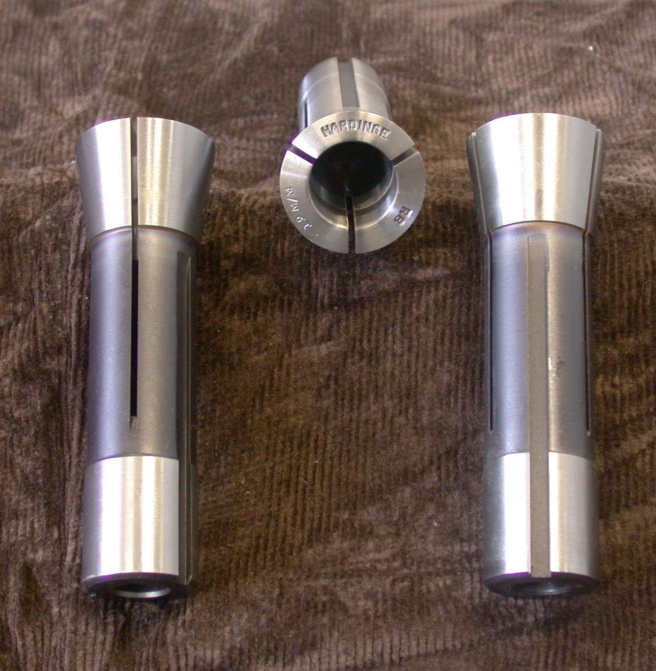
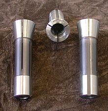 collets with R8 taper
This taper was designed by Bridgeport Machines, Inc. of the USA for use in their milling machines. It is intended that collets be inserted directly into the machine taper, which is not usual with other tapers (except very occasionally with Morse). Collets must be used with a drawbar extending up through the spindle to the top of the machine to prevent the collet from falling from the spindle when lateral forces are encountered. The collet has a precision hole in one end for holding a cutting tool and is threaded for a drawbar on other end. They are also keyed (see image) to prevent rotation during insertion and removal. However, cutting torques are transferred through friction at the taper, not through the key. The drawbar thread is typically 7/16"-20 tpi (UNF).
The R8 system can accept tools with a nominal 3/4" shank diameter. Smaller tools are generally held using a toolholder with a 3/4" shank diameter. The cutting tool or toolholder is placed in the collet, the collet placed into the taper, and the drawbar is tightened into the top of the collet from above the spindle. The collet has a groove to engage a key in the spindle to keep the collet from spinning inside the taper and to aid in the installation and removal of the collet. The angle of the cone is typically 16 degrees and 51 minutes (i.e. 16.85 degrees) with an OD of 1.25" (source, Bridgeport Manufacturer).
The R8 taper is commonly encountered on Bridgeport and similar turret mills from the USA, or on (very common) copies of these mills from elsewhere.[citation needed] The popularity is due in large part to the success of Bridgeport and other mills that were closely modeled after it and produced throughout much of the 20th century.
Jacobs
The Jacobs Taper (abbreviated JT) is commonly used to secure drill press chucks to an arbor.
Taper Small End Big End Length mm inch mm inch mm inch 0 5.80 0.2284 6.35 0.2500 11.11 0.4375 1 8.47 0.3334 9.75 0.3840 16.67 0.6563 2 12.39 0.4876 14.20 0.5590 22.23 0.8750 2 Short 12.39 0.4876 13.94 0.5488 19.05 0.7500 2½ 15.88 0.625 17.20 0.677 26.80 1.055 3 18.95 0.7461 20.60 0.8110 30.96 1.2188 4 26.34 1.0372 28.55 1.1240 42.07 1.6563 5 33.43 1.3161 35.89 1.4130 47.63 1.8750 6 15.85 0.6241 17.17 0.6760 25.40 1.0000 33 14.23 0.5604 15.85 0.6240 25.40 1.0000 Jarno
Jarno tapers use a greatly simplified scheme. The rate of taper is 1:20 on diameter, in other words 0.600" on diameter per foot, .050" on diameter per inch. Tapers range from a Number 2 to a Number 20. The diameter of the big end in inches is always the taper size divided by 8, the small end is always the taper size divided by 10 and the length is the taper size divided by 2. For example a Jarno #7 measures 0.875" (7/8) across the big end. The small end measures 0.700" (7/10) and the length is 3.5" (7/2).
The system was invented by Oscar J. Beale of Brown & Sharpe.
Jarno Tapers
Taper Large End Small End Length Taper/
FootTaper/
InchAngle From Center #2 0.2500 0.2000 1.00 .6000 .0500 1.4321 #3 0.3750 0.3000 1.50 .6000 .0500 1.4321 #4 0.5000 0.4000 2.00 .6000 .0500 1.4321 #5 0.6250 0.5000 2.50 .6000 .0500 1.4321 #6 0.7500 0.6000 3.00 .6000 .0500 1.4321 #7 0.8750 0.7000 3.50 .6000 .0500 1.4321 #8 1.0000 0.8000 4.00 .6000 .0500 1.4321 #9 1.1250 0.9000 4.50 .6000 .0500 1.4321 #10 1.2500 1.0000 5.00 .6000 .0500 1.4321 #11 1.3750 1.1000 5.50 .6000 .0500 1.4321 #12 1.5000 1.2000 6.00 .6000 .0500 1.4321 #13 1.6250 1.3000 6.50 .6000 .0500 1.4321 #14 1.7500 1.4000 7.00 .6000 .0500 1.4321 #15 1.8750 1.5000 7.50 .6000 .0500 1.4321 #16 2.0000 1.6000 8.00 .6000 .0500 1.4321 #17 2.1250 1.7000 8.50 .6000 .0500 1.4321 #18 2.2500 1.8000 9.00 .6000 .0500 1.4321 #19 2.3750 1.9000 9.50 .6000 .0500 1.4321 #20 2.5000 2.0000 10.00 .6000 .0500 1.4321 NMTB Tapers
The National Machine Tool Builders Association (now called the Association for Manufacturing Technology) in the USA laid down standards for machine tool design, among other things: the taper used on CNC (Computer Numerically Controlled) milling machines.
The taper is variously referred to as NMTB, NMT or NT. Essentially this defines a taper of 3.500 inches per foot or 16.7112 degrees (also referred to as "7 in 24" or 7/24. All NMTB Tooling has this taper but the tooling comes in different sizes. NMTB-10, 15, 20, 25, 30, 35, 40, 45, 50 and 60. With the 40 taper being the most common by far.
CAT, V Flange,SK, ISO (also known as INT, Inter or International) and BT tooling use this same taper: the difference is in the flanges and pull studs (a male extension from the drawbar thread, used in CNC machines with toolchangers and/or power drawbars).
This is a "self releasing" or "Fast" taper. Unlike the more acute self holding tapers above, such tapers are not designed to transmit torque. This turning effort is carried by driving keys engaging slots on the flange. The purpose is to allow a quick and easy change between different tools (either automatically or by hand) while ensuring the tool or toolholder will be tightly and rigidly connected to the spindle, and accurately coaxial with it. The larger end adjacent to the tool makes for more rigidity than is possible with Morse or RT tapers fitted to comparable machines.
The spindle on the machine tool is built with a female taper and drawbar. Each individual tool must be fitted with a male taper and the proper adapter for the drawbar.
References
- Machine Tools -- Self-holding tapers for tool shanks, ISO, 1991, ISO 296:1991, http://www.iso.org/iso/iso_catalogue/catalogue_tc/catalogue_detail.htm?csnumber=4224
External links
- Beautiful Iron Overview of Tapers
- Quickly Identify your Morse Taper
- http://www.tools-n-gizmos.com/specs/Tapers.html (description of several tool holders)
- http://www.timgoldstein.com/cad_cam/tapers.htm (description of several tool holders)
Metalworking Machining and computing Computer-aided engineering Drilling and threading Grinding and lapping Abrasive · Angle grinder · Bench grinder · Coated abrasives · Cylindrical grinder · Diamond plate · Flick grinder · Dresser · Grinding · Grinding machine · Grinding wheel · Jig grinder · Lapping · Sanding · Sharpening stone · Spark testing · Surface grinder · Tool and cutter grinderMachining and milling Electrical discharge machining · Electrochemical machining · Endmill · Engraving · Hobbing · Lathe · Machine tool · Machining · Milling cutter · Milling machine · Planer · Pantograph · ShaperMachine tooling Angle plate · Chuck · Collet · Jig · Fixture · Indexing head · Lathe center · Machine taper · Magnetic base · Mandrel · Rotary table · WigglerTerminology Casting · Fabrication · Forming · Jewellery · Machining · Metallurgy · Smithing · Tools and terminology · Welding Categories:- Machine tools
- Woodworking

Wikimedia Foundation. 2010.