- Movie projector
-
- This article is concerned with technical aspects of moving film projection. For non-film movie projection, see digital cinema. For historical aspects, see the article history of cinema.
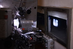 35 mm movie projector in operation.
 35 mm movie projector with enclosed type spool boxes, optical and magnetic soundheads and Xenon lamphouse
A movie projector is an opto-mechanical device for displaying moving pictures by projecting them on a projection screen. Most of the optical and mechanical elements, except for the illumination and sound devices, are present in movie cameras.
Contents
Physiology
According to the theory of persistence of vision, the perceptual processes of the brain and the retina of the human eye retain an image for a brief moment of time. This theory is said to account for the illusion of motion which results when a series of film images is displayed in quick succession, rather than the perception of the individual frames in the series.
Persistence of vision should be compared with the related phenomena of beta movement and phi movement. A critical part of understanding these visual perception phenomena is that the eye is not a camera, i.e.: there is no "frame rate" or "scan rate" in the eye. Instead, the eye/brain system has a combination of motion detectors, detail detectors and pattern detectors, the outputs of all of which are combined to create the visual experience.
The frequency at which flicker becomes invisible is called the flicker fusion threshold, and is dependent on the level of illumination. Generally, the frame rate of 16 frames per second (frame/s) is regarded as the lowest frequency at which continuous motion is perceived by humans. (Interestingly this threshold varies across different species; a higher proportion of rod cells in the retina will create a higher threshold level.)
It is possible to view the black space between frames and the passing of the shutter by the following technique:
Close your eyelids, then periodically rapidly blink open and closed. If done fast enough you will be able to randomly "trap" the image between frames, or during shutter motion. This will not work with television due to the persistence of the phosphors nor with LCD or DLP light projectors due to the continuity of image, although certain color artifacts may appear with some digital projection technologies.Silent films usually were not projected at constant speeds [1] but rather were varied throughout the show at the discretion of the projectionist, often with some notes provided by the distributor. Speeds ranged from about 18 frame/s on up - sometimes even faster than modern sound film speed (24 frame/s). Contrary to received opinion, 16 frame/s - though sometimes used as a camera shooting speed - was dangerously inadvisable for projection, due to the high risk of the nitrate-base prints catching fire in the projector. (A dramatic rendition of a nitrate print fire and its potentially devastating effects is famously found in Nuovo Cinema Paradiso, which revolves around the goings-on of a projectionist.)
Since the birth of sound film, virtually all film projectors in commercial movie theaters project at a constant speed of 24 frame/s. This speed was chosen for both financial and technical reasons. When Warner Bros. and Western Electric were trying to find the proper projection speed for the new sound pictures, Western Electric went to the Warner Theater in LA and noted the AVERAGE speed at which films were projected there. They set that as the sound speed at which a satisfactory reproduction and amplification of sound could be conducted. There are some specialist formats (e.g. Showscan and Maxivision) which project at higher rates, often 48 frame/s.
Principles of operation
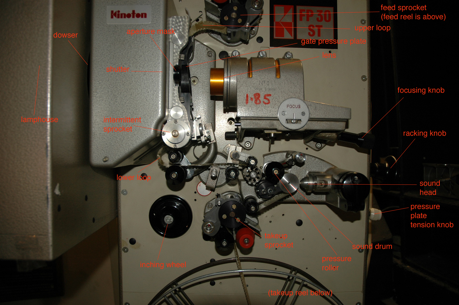
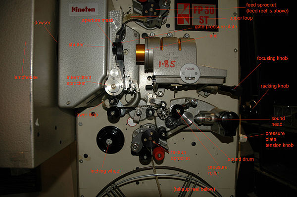 35 mm Kinoton FP30ST movie projector, with parts labeled. (Click thumbnail for larger text.)
Projection elements
As in a slide projector there are essential optical elements:
Light source
Incandescent lighting and even limelight were the first light sources used in film projection. In the early 1900s up until the late 1960s, carbon arc lamps were the source of light in the almost all theaters in the world.
The Xenon arc lamp was introduced in Germany in 1957 and in the US in 1963. After film platters became commonplace in the 1970s, Xenon lamps became the most common light source, as they could stay lit for extended periods of time, whereas a carbon rod used for a carbon arc could last for an hour at the most.
Most lamp houses in a professional theatrical setting produce sufficient heat to burn the film should the film remain stationary for more than a fraction of a second. Because of this, care must be taken in inspecting a film so that it should not break in the gate and be damaged, particularly inflammable cellulose nitrate film stock.
Reflector and condenser lens
A curved reflector redirects light that would otherwise be wasted toward the condensing lens.
A positive curvature lens concentrates the reflected and direct light toward the film gate.
Douser
(Also spelled dowser.)
A metal or asbestos blade which cuts off light before it can get to the film. The douser is usually part of the lamphouse, and may be manually or automatically operated. Some projectors have a second, electrically controlled douser that is used for changeovers (sometimes called a "changeover douser" or "changeover shutter"). Some projectors have a third, mechanically controlled douser that automatically closes when the projector slows down (called a "fire shutter" or "fire douser"), to protect the film if the projector stops while the first douser is still open. Dousers protect the film when the lamp is on but the film is not moving, preventing the film from melting from prolonged exposure to the direct heat of the lamp. It also prevents the lens from scarring or cracking from excessive heat.
Film gate and single image
A single image of the series of images comprising the movie is positioned and held flat within an aperture called the gate. The gate also provides a slight amount of friction so that the film does not advance or retreat except when driven to advance the film to the next image.
Shutter
A commonly held misconception is that film projection is simply a series of individual frames dragged very quickly past the projector's intense light source; this is not the case. If a roll of film were merely passed between the light source and the lens of the projector, all that would be visible on screen would be a continuous blurred series of images sliding from one edge to the other. It is the shutter that gives the illusion of one full frame being replaced exactly on top of another full frame. A rotating petal or gated cylindrical shutter interrupts the emitted light during the time the film is advanced to the next frame. The viewer does not see the transition, thus tricking the brain into believing a moving image is on screen. Modern shutters are designed with a flicker-rate of two times (48 Hz) or even sometimes three times (72 Hz) the frame rate of the film, so as to reduce the perception of screen flickering. (See Frame rate and Flicker fusion threshold.) Higher rate shutters are less light efficient, requiring more powerful light sources for the same light on screen.

Mechanical sequence when image is shown twice and then advanced.
Outer sprockets rotate continuously while the frame advance sprockets are controlled by the mechanism shown - a Geneva drive.Imaging lens and aperture plate
A projection objective with multiple optical elements directs the image of the film to a viewing screen (imaging lens). Imaging lenses also differ in aperture and focal length. Different lenses are used for different aspect ratios.
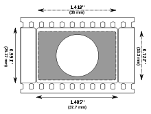
Aspect ratios are controlled by the lens with the appropriate aperture plate, a piece of metal with a precisely cut rectangular hole in the middle of equivalent aspect ratio. The aperture plate is placed just behind the gate, and masks off any light from hitting the image outside of the area intended to be shown. All films, even those in the standard Academy ratio, have extra image on the frame that is meant to be masked off in the projection.
Viewing screen
In most cases this is a reflective surface which may be either aluminized (for high contrast in moderate ambient light) or a white surface with small glass beads (for high brilliance under dark conditions). Switchable projection screen can be switched between opaque and clear by a safe voltage under 36V AC and is viewable from both sides. In a commercial theater, the screen also has millions of very small, evenly spaced holes in order to allow the passage of sound from the speakers and subwoofer which often are directly behind it.
Film transport elements
Film supply and takeup
Two-reel system
In the two-reel system the projector has 2 reels- one is the feed reel, which holds the part of the film that has not been shown, the other is the takeup reel, which winds the film that has been shown onto a second, empty, reel. In a two-reel projector the feed reel has a slight drag to maintain tension on the film, while the takeup reel is constantly driven with a mechanism that has mechanical 'slip,' to allow the film to be wound under constant tension so the film is wound in a smooth manner.
The film being wound on the takeup reel is being wound 'head in' or 'tails out.' This means that the beginning of the reel is in the center, where it is inaccessible. As each reel is taken off of the projector, it must be re-wound onto another empty reel. In a theater setting there is often a separate machine for rewinding reels. For the 16 mm projectors often used in schools and churches, the projector could be re-configured to rewind films.
The size of the reels can vary based on the projectors, but generally films are divided and distributed in reels of up to 2000 feet (610 m, about 22 minutes at 24 frame/s). Some projectors can even accommodate up to 6000 feet (1,830 m), which minimizes the number of changeovers (see below) in a showing. Certain countries also divide their film reels up differently; Russian films, for example, often come on 1000 foot (305 m) reels, although it's likely that most projectionists working with changeovers would combine them into longer reels of at least 2000 feet (610 m), to minimize changeovers and also give sufficient time for threading and any possibly needed troubleshooting time.
Films are identified as 'short subjects,' taking 1 reel or less of film, 'two-reelers,' required two reels of film (some of the early Laurel & Hardy, 3 Stooges, and other comedies were two-reelers), and 'features' could take any number of reels (although most are limited to 1-1/2 to 2 hours, enabling the theater to have multiple showings throughout the day and evening, each showing with a feature, commercials, and intermission to allow the audiences to change). In the 'old days,' (1930–1960), when you 'went to the movies' you'd see a short subject (a newsreel, short documentary, a "2-reeler," etc.), a cartoon, and the feature. Some theaters would have movie-based commercials for local businesses, and the state of New Jersey required showing a diagram of the theater showing all of the exits.
Changeover
Because a single film reel does not contain enough film to show an entire feature, the film is distributed on multiple reels. To prevent having to interrupt the show when one reel ends and the next is mounted, two projectors are used in what is known as a 'changeover system,' after the switching mechanism that operates between the end of one reel on the first projector and the beginning of the next reel on the second projector. The two-reel system was used almost universally for movie theaters before the advent of the single-reel system in order to be able to show feature-length films. Although one-reel long-play systems tend to be more popular with the newer multiplexes, the two reel system is still in significant use to this day.
The projector operator operates two projectors, starting the 1st reel of the show on projector "A." While this reel is being shown, the projectionist threads the 2nd reel on projector "B."
As the reel being shown approaches its end, the projectionist looks for cue marks at the upper-right corner of the picture. Usually these are dots or circles, although they can also be slashes. Some older films occasionally used squares or triangles, and sometimes positioned the cues in the middle of the right edge of the picture.
The first cue appears twelve feet (3.7 m) before the end of the program on the reel. That's eight seconds at 24 frame/s. This cue signals the projectionist to start the motor of the projector containing the next reel. After another ten and a half feet (3.2 m)of film is shown (seven seconds at 24 frame/s), the changeover cue should appear, which signals the projectionist to actually make the changeover. When this second cue appears, the projectionist has one and a half feet (457 mm), or one second at 24 frame/s, to make the changeover. If it doesn't occur within one second, the tail leader of the reel coming to an end will be projected on the screen.
See the note below on "Leaders--" twelve feet before the "First Frame Of Action," Academy leaders have a 'START' frame. The projectionist positions the 'start' in the gate of the projector. When the first cue is seen, the motor of the starting projector is started. Seven seconds later the end of the leader and start of program material on the new reel should just reach the gate of the projector when the changeover cue is seen.
On some projectors, the operator would be alerted to the time for a change by a bell that operated when the feed reel rotation exceeded a certain speed (the feed reel rotates faster as the film is exhausted), or based on the diameter of the remaining film (Premier Changeover Indicator Pat.411992), although many projectors do not have such an auditory system.
During the actual operation of a changeover, the two projectors use an interconnected electrical control connected to the changeover button so that as soon as the button is pressed, the changeover douser on the outgoing projector is closed in sync with the changeover douser on the incoming projector opening. If done properly, a changeover should be virtually unnoticeable to an audience. In older theaters, there may be manually operated, sliding covers in front of the projection booth's windows. A changeover with this system is often clearly visible as a wipe on the screen.
Once the changeover has been made, the projectionist unloads the full takeup reel from projector "A," moves the now-empty reel (that used to hold the film just unloaded) from the feed spindle to the takeup spindle, and loads reel #3 of the presentation on projector "A." When reel 2 on projector "B" is finished, the changeover switches the live show from projector "B" back to projector "A," and so on for the rest of the show.
When the projectionist removes a finished reel from the projector it is 'tails out,' and needs to be rewound before the next show. The projectionist usually uses a separate rewind machine and a spare empty reel, and rewinds the film so it is 'head out,' ready to project again for the next show.
Single reel system
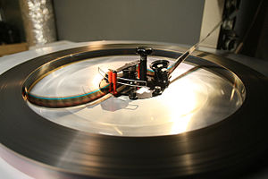
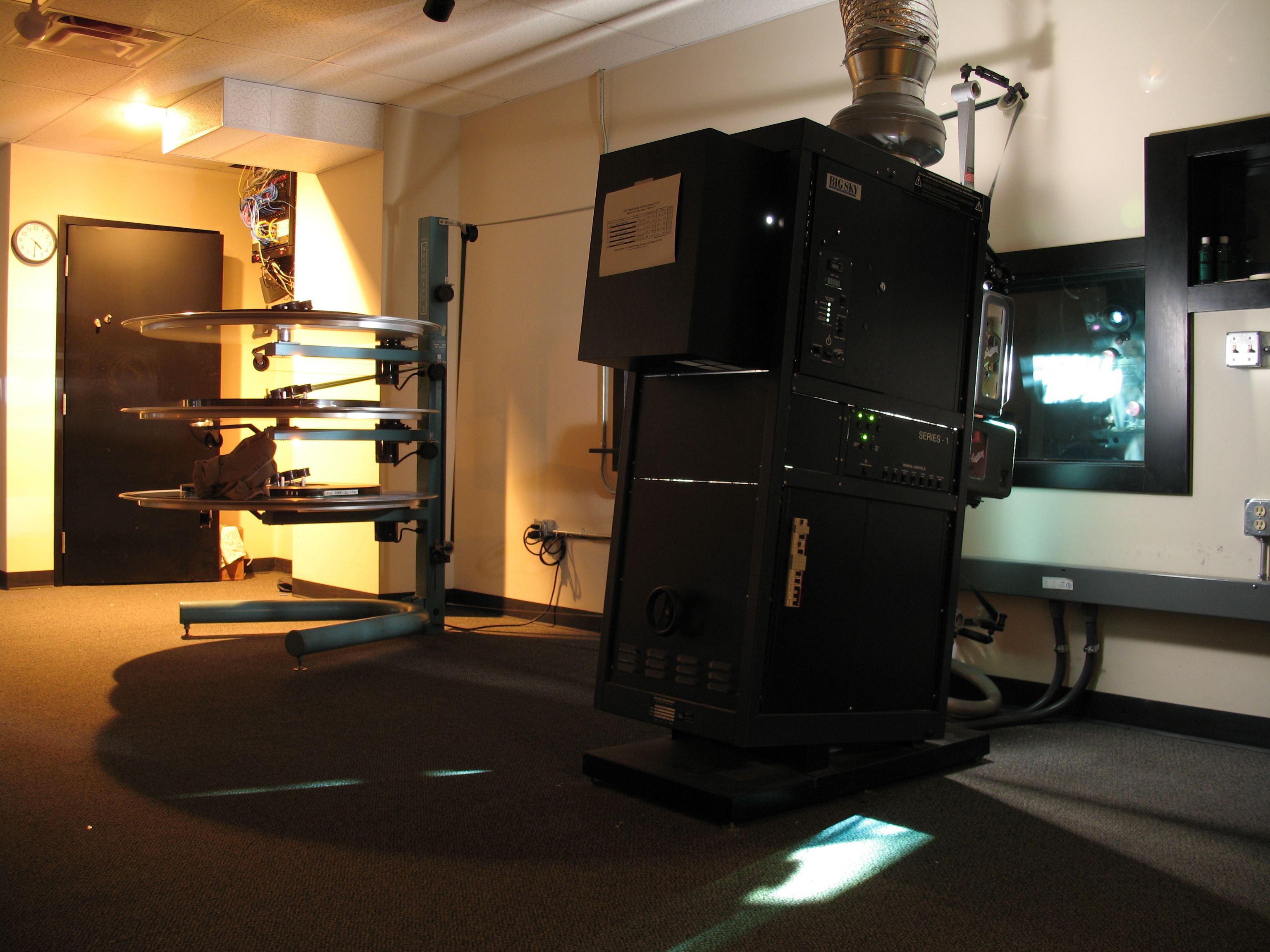
 Christie AW3 platter, BIG SKY Industries console, and Century SA projector.
There are two largely used single reel systems (also known as long-play systems) today: the tower system (vertical feed and takeup) and the platter system (non-rewinding; horizontal feed and takeup).
The tower system largely resembles the two reel system, except in that the tower itself is generally a separate piece of equipment used with a slightly modified standard projector. The feed and takeup reels are held vertically on the axis, except behind the projector, on oversized spools with 12,000 foot (3,660 m) capacity or about 133 minutes at 24 frame/s. This large capacity alleviates the need for a changeover on an average-length feature; all of the reels are spliced together into one giant one. The tower is designed with four spools, two on each side, each with its own motor. This allows the whole spool to be immediately rewound after a showing; the extra two spools on the other side allow for a film to be shown while another is being rewound or even made up directly onto the tower. Each spool requires its own motor in order to set proper tensioning for the film, since it has to travel (relatively) much further between the projector film transport and the spools. As each spool gains or loses film, the tension must be periodically checked and adjusted so that the film can be transported on and off the spools without either sagging or snapping.
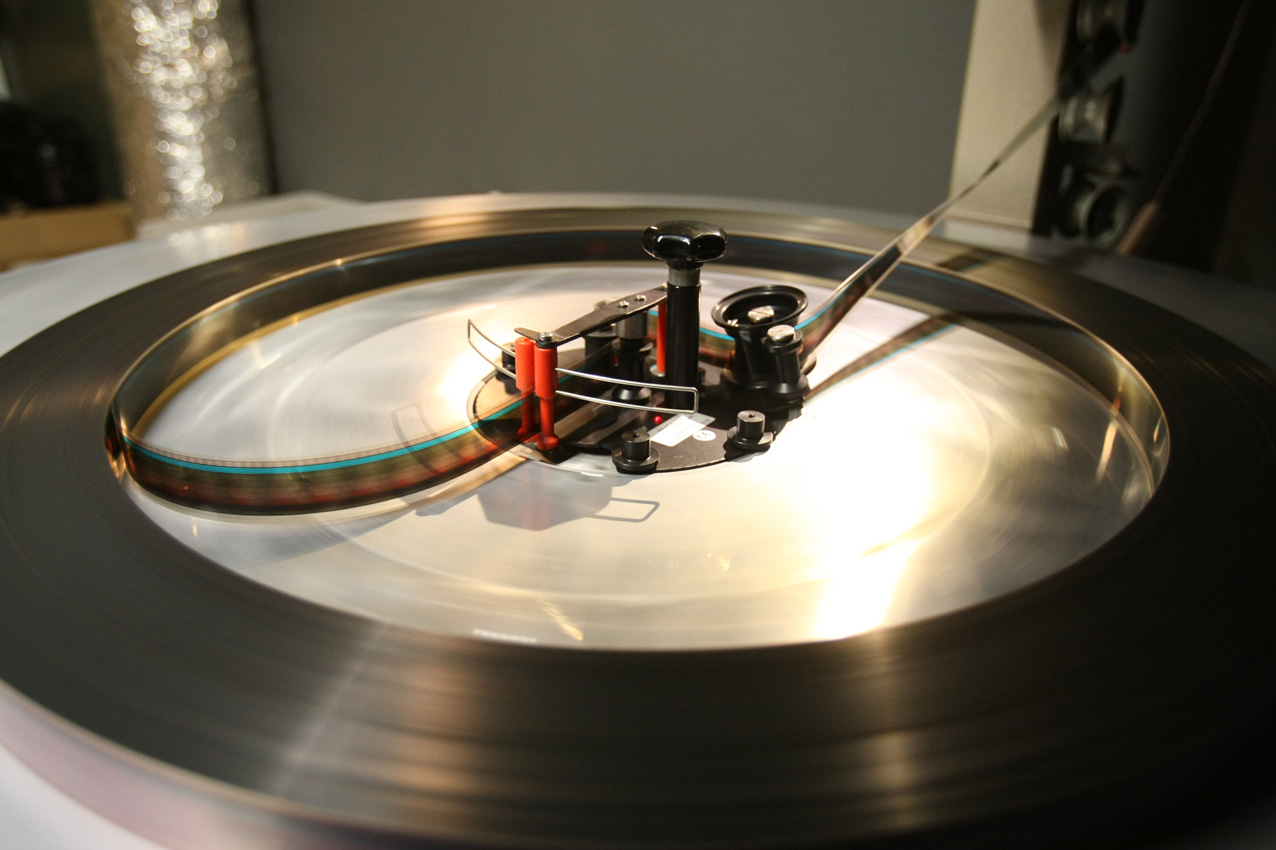
In a platter system the individual 20-minute reels of film are also spliced together as one large reel, but the film is then wound onto a horizontal rotating table called a platter. Three or more platters are stacked together to create a platter system. Most of the platters in a platter system will be occupied by film prints; whichever platter happens to be empty serves as the "take-up reel" to receive the film that is playing from another platter.
The way the film is fed from the platter to the projector is not unlike an eight-track audio cartridge. Film is unwound from the center of the platter through a mechanism called a payout unit which controls the speed of the platter's rotation so that it matches the speed of the film as it is fed to the projector. The film winds through a series of rollers from the platter stack to the projector, through the projector, through another series of rollers back to the platter stack, and then onto the platter serving as the take-up reel.
This system makes it possible to project a film multiple times without needing to rewind it. As the projectionist threads the projector for each showing, he transfers the payout unit from the empty platter to the full platter and the film then plays back onto the platter it came from. In the case of a double feature, each film plays from a full platter onto an empty platter, swapping positions on the platter stack throughout the day.
 nonrewind in Royal - Malmo, Sweden.
The advantage of a platter is that the film need not be rewound after each show, which can save labor. Rewinding risks rubbing the film against itself, which can cause scratching of the film and smearing of the emulsion which carries the pictures. The disadvantages of the platter system are that the film can acquire diagonal scratches on it if proper care is not taken while threading film from platter to projector, and the film has more opportunity to collect dust and dirt as long lengths of film are exposed to the air. A clean projection booth kept at the proper humidity is of great importance, as are cleaning devices that can remove dirt from the film print as it plays.
Automation and the rise of the multiplex
The single reel system can allow for the complete automation of the projection booth operations, given the proper auxiliary equipment. Since films are still transported in multiple reels they must be joined together when placed on the projector reel and taken apart when the film is to be returned to the distributor. It is the complete automation of projection that has enabled the modern "multiplex" cinema - a single site typically containing from 8 to 24 theaters with only a few projection and sound technicians, rather than a platoon of projectionists. The multiplex also offers a great amount of flexibility to a theater operator, enabling theaters to exhibit the same popular production in more than one auditorium with staggered starting times. It is also possible, with the proper equipment installed, to "interlock", i.e. thread a single length of film through multiple projectors. This is very useful when dealing with the mass crowds that an extremely popular film may generate in the first few days of showing, as it allows for a single print to serve more patrons.
Feed and extraction sprockets
Smooth wheels with triangular pins called sprockets engage perforations punched into one or both edges of the film stock. These serve to set the pace of film movement through the projector and any associated sound playback system.
Film loop
As with motion picture cameras, the intermittent motion of the gate requires that there be loops above and below the gate in order to serve as a buffer between the constant speed enforced by the sprockets above and below the gate and the intermittent motion enforced at the gate. Some projectors also have a sensitive trip pin above the gate to guard against the upper loop becoming too big. If the loop hits the pin, it will close the dousers and stop the motor to prevent an excessively large loop from jamming the projector.
Film gate pressure plate
A spring-loaded pressure plate functions to align the film in a consistent image plane, both flat and perpendicular to the optical axis. It also provides sufficient drag to prevent film motion during the frame display, while still allowing free motion under control of the intermittent mechanism. The plate also has spring-loaded runners to help hold film while in place and advance it during motion.
Intermittent mechanism
The intermittent mechanism can be constructed in different ways. For smaller gauge projectors (8 mm and 16 mm), a pawl mechanism engages the film's sprocket hole one side, or holes on each side. This pawl advances only when the film is to be moved to the next image. As the pawl retreats for the next cycle it is drawn back and does not engage the film. This is similar to the claw mechanism in a motion picture camera.
In 35 mm and 70 mm projectors, there usually is a special sprocket immediately underneath the pressure plate, known as the intermittent sprocket. Unlike all the other sprockets in the projector, which run continuously, the intermittent sprocket operates in tandem with the shutter, and only moves while the shutter is blocking the lamp, so that the motion of the film cannot be seen. It also moves in a discrete amount at a time, equal to the number of perforations that make up a frame (4 for 35 mm, 5 for 70 mm). The intermittent movement in these projectors is usually provided by a Geneva drive, also known as the Maltese Cross mechanism.
IMAX projectors use what is known as the rolling loop method, in which each frame is sucked into the gate by a vacuum, and positioned by registration pins in the perforations corresponding to that frame.
Types of projectors
Projectors are classified by the size of the film used, i.e. the film format. Typical film sizes:
8 mm
Long used for home movies before the video camera, this uses double sprocketed 16 mm film, which is run through the camera twice. The 16 mm film is then split lengthwise into two 8 mm pieces that are spliced to make a single projectable film with sprockets on one side.
Super 8
Developed by Kodak, this film stock uses very small sprocket holes close to the edge that allow more of the film stock to be used for the images. This increases the quality of the image. The unexposed film is supplied in the 8 mm width, not split during processing as is the earlier 8 mm. Magnetic stripes could be added to carry encoded sound to be added after film development.
9.5 mm
Film format introduced by Pathé Frères in 1922 as part of the Pathé Baby amateur film system. It was conceived initially as an inexpensive format to provide copies of commercially made films to home users. The format uses a single, central perforation (sprocket hole) between each pair of frames, as opposed to 8 mm film which has perforations along one edge, and most other film formats which have perforations on each side of the image. It became very popular in Europe over the next few decades and is still used by a small number of enthusiasts today. Over 300,000 projectors were produced and sold mainly in France and England, and many commercial features were available in the format. In the sixties the last projectors of this format were being produced. They are now collectors' items.
16 mm
This was a popular format for audio-visual use in schools and as a high-end home entertainment system before the advent of broadcast television. The most popular home content were comedic shorts (typically less than 20 minutes in length in the original release) and bundles of cartoons previously seen in movie theaters. 16 mm enjoys widespread use today as a format for short films, independent features and music videos, being a relatively economical alternative to 35 mm.
35 mm
The most common film size for theatrical productions during the 20th century. In fact, the common 35 mm camera, developed by Leica, was designed to use this film stock and was originally intended to be used for test shots by movie directors and cinematographers.[citation needed]
35 mm film is typically run vertically through the camera and projector. In the mid-1950s the VistaVision[1] system presented wide screen movies in which the film moved horizontally, allowing much more film to be used for the image as this avoided the anamorphic reduction of the image to fit the frame width. As this required specific projectors it was largely unsuccessful as a presentation method while remaining attractive as filming, intermediate, and source for production printing and as an intermediate step in special effects to avoid film granularity, although the latter is now supplanted by digital methods.
70 mm
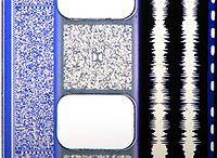 A photo of a 35 mm film print featuring all four audio formats (or "quad track")- from left to right: SDDS (blue area to the left of the sprocket holes), Dolby Digital (grey area between the sprocket holes labelled with the Dolby "Double-D" logo in the middle), analog optical sound (the two white lines to the right of the sprocket holes), and the DTS time code (the dashed line to the far right.)
High-end movie productions were often produced in this film gauge in the 1950s and 1960s and many very large screen theaters are still capable of projecting it in the 21st century. It is often referred to as 65/70, as the camera uses film 65 mm wide, but the projection prints are 70 mm wide. The extra five millimeters of film accommodated the soundtrack, usually a six track magnetic stripe. The most common theater installation would use dual gauge 35/70mm projectors.
70 mm film is also used in both the flat and domed IMAX projection system. In IMAX the film is transported horizontally in the film gate, similar to VistaVision. Some productions intended for 35 mm anamorphic release were also released using 70 mm film stock. A 70 mm print made from a 35 mm negative is significantly better in appearance than an all-35 mm process, and allowed for a release with 6 track magnetic audio.
The advent of 35 mm prints with digital soundtracks in the 1990s largely supplanted the widespread release of the more expensive 70 mm prints.
Sound
Regardless of the sound format, any sound represented on the film image itself will not be the sound for the particular frame it occupies. In the gate of the projector head, there is no space for a reader, and the film is not travelling smoothly at the gate position. Consequently, all optical sound formats must be offset from the image because the sound reader is usually located above (for magnetic readers) or below (for optical readers) the projector head.
- See the 35 mm film article for more information on both digital and analog methods.
Analog Optical Sound
Optical sound constitutes the recording and reading of amplitude based on the amount of light that is projected through a soundtrack area on a film using an illuminating light or laser and a photocell or photodiode. As the photocell picks up the light in varying intensities, the electricity produced is intensified by an amplifier, which in turn powers a loudspeaker, where the electrical impulses are turned into air vibrations and thus, sound waves. In 16 mm, this optical soundtrack is a single mono track placed on the right side of the projected image, and the sound head is 26 frames after the gate. In 35 mm, this can be mono or stereo, on the left side of the projected image, with the sound head 21 frames after the gate .[2]
The first form of optical sound was represented by horizontal bands of clear (white) and solid (black) area. The space between solid points represented amplitude and was picked up by the photo-electric cell on the other side of a steady, thin beam of light being shined through it. This variable density form of sound was eventually phased out because of its incompatibility with color stocks. The alternative and ultimately the successor of variable density has been the variable area track, in which a clear, vertical waveform against black represents the sound, and the width of the waveform is equivalent to the amplitude. Variable area does have slightly less frequency response than variable density, but because of the grain and variable infrared absorption of various film stocks, variable density had a lower signal-to-noise ratio.
Optical stereo is recorded and read through a bilateral variable area track, recorded using Dolby Stereo matrix encoding and Dolby noise reduction. Left, center, right and surround channels are matrix-encoded into these two tracks.
In the 1970s and early 1980s, optical sound Super-8 mm copies were produced mainly for airline in-flight movies. Even though technology was soon made obsolete by video equipment, the majority of small-gauge films used magnetic sound rather than optical sound for a higher frequency range.
Magnetic sound
Magnetic sound is no longer used in commercial cinema, but between 1952 and the early 1990s it provided the highest fidelity sound from film because of its wider frequency range and superior signal to noise ratio compared to optical sound. There are two forms of magnetic sound in conjunction with projection: double-head and striped.
The first form of magnetic sound was the double-head system, in which the movie projector was interlocked with a dubber playing a 35 mm reel of a full-coat, or film completely coated with magnetic iron-oxide. This was introduced in 1952 with Cinerama, holding six tracks of stereophonic sound. Stereophonic releases throughout 1953 also used an interlocked full-coat for three-channel stereophonic sound.
In interlock, since the sound is on a separate reel, it does not need to be offset from the image. Today, this system is usually used only for very low-budget or student productions, or for screening rough cuts of films before the creation of a final married print. Sync between the two reels is checked with SMPTE leader, also known as countdown leader. If the two reels are synced, there should be one frame of "beep" sound exactly on the "2" frame of the countdown - 2 seconds or 48 frames before the picture start.
Striped magnetic film is motion picture film in which 'stripes' of magnetic oxide are placed on the film between the sprocket holes and the edge of the film, and sometimes also between the sprocket holes and the image. Each of these stripes has one channel of the audio recorded on it. This technique was first introduced in September, 1953 by Hazard E. Reeves for Cinemascope. Four tracks are present on the film: Left, Center, Right and Surround. This 35mm four-track magnetic sound format was used from 1954 through 1982 for "roadshow" screenings of big-budget feature films.
70 mm, which had no optical sound, used the 5 millimeters gained between the 65 mm negative and the final release print to place three magnetic tracks outside of the perforations on each side of the film for a total of six tracks. Until the introduction of digital sound, it was fairly common for 35 mm films to be blown up to 70 mm often just to take advantage of the greater number of sound tracks and the fidelity of the audio.
Although magnetic audio was of excellent quality it also had significant disadvantages. Magnetic sound prints were expensive, 35mm magnetic prints cost roughly twice as much as optical sound prints, whilst 70mm prints could cost up to 15 times as much. Furthermore they wore out faster and were also prone to damage and erasure over time. Because of the high cost of installing magnetic sound reproduction equipment only a minority of movie theaters ever installed it and the magnetic soundheads needed considerable maintenance to keep their performance up to standard. As a consequence the use of the Cinemascope 35mm four-track magnetic sound format decreased significantly during the course of the 1960s and effectively ended with the success of the Dolby Stereo optical stereo format in the late 1970s. However 70mm film continued to be used for prestigious "roadshow" screenings until the introduction of digital sound on 35mm film in the early 1990s removed one of the major justifications for using this expensive format.
On certain stocks of Super 8 and 16 mm an iron-oxide sound recording strip was added for the direct synchronous recording of sound which could then be played by projectors with a magnetic sound head. It has since been discontinued by Kodak on both gauges.
Digital
Modern theatrical systems use optical representations of digitally encoded multi-channel sound. An advantage of digital systems is that the offset between the sound and picture heads can be varied and then set with the digital processors. Digital sound heads are usually above the gate. All digital sound systems currently in use have the ability to instantly and gracefully fall back to the analog optical sound system should the digital data be corrupt or the whole system fail.
Cinema Digital Sound (CDS)
Created by Kodak and ORC (Optical Radiation Corporation), Cinema Digital Sound was the first attempt to bring multi-channel digital sound to first-run theaters. CDS was available on both 35 mm and 70 mm films. Film prints equipped with CDS did not have the conventional analog optical or magnetic soundtracks to serve as a back-up in case the digital sound was unreadable. Another disadvantage of not having an analog back-up track is that CDS required extra film prints be made for the theaters equipped to play CDS. The three formats that followed, Dolby Digital, DTS and SDDS, can co-exist with each other and the analog optical soundtrack on a single version of the film print. This means that a film print carrying all three of these formats (and the analog optical format, usually Dolby SR) can be played in whichever format the theater is equipped to handle. CDS did not achieve widespread use and ultimately failed. It premiered with the film Dick Tracy and was used with several other films, such as Days of Thunder and Terminator 2: Judgement Day.
Sony Dynamic Digital Sound (SDDS)
SDDS runs on the outside of 35 mm film, between the perforations and the edges, on both edges of the film. It was the first digital system that could handle up to eight channels of sound. The additional two tracks are for an extra pair of screen channels (Left Center and Right Center) located between the 3 regular screen channels (Left, Center and Right). A pair of CCDs located in a unit above the projector reads the two SDDS tracks. The information is decoded and decompressed before being passed along to the cinema sound processor. By default, SDDS units use an onboard Sony Cinema Sound Processor, and when the system is set up in this manner, the theatre's entire sound system can be equalized in the digital domain. The audio data in an SDDS track is compressed in the 20-bit ATRAC2 compression scheme at a ratio of about 4.5:1. SDDS premiered with the film Last Action Hero. SDDS was the least commercially successful of the three competing digital sound systems for 35mm film. Sony ceased the sale of SDDS processors in 2001-2002.
Dolby Digital
Dolby Digital data is printed in the spaces between the perforations on the soundtrack side of the film, 26 frames before the picture. Release prints with Dolby Digital always include an analog Dolby Stereo soundtrack with Dolby SR noise reduction, thus these prints are known as Dolby SR-D prints. Dolby Digital produces 6 discrete channels. In a variant called SR-D EX, the left and right surround channels can be dematrixed into left, right, and back surround, using a matrix system similar to Dolby Pro Logic. The audio data in a Dolby Digital track is compressed in the 16-bit AC-3 compression scheme at a ratio of about 12:1. The images between each perforation are read by a CCD located either above the projector or in the regular analog sound head below the film gate, a digital delay within the processor allowing correct lip-sync to be achieved regardless of the position of the reader relative to the picture gate. The information is then decoded, decompressed, and converted to analog; this can happen either in a separate Dolby Digital processor that feeds signals to the cinema sound processor, or digital decoding can be built into the cinema processor.
In 2006 Dolby discontinued the sale of their external SR-D processor (the DA20), but included Dolby Digital decoding in their CP500 and later CP650 cinema processors.
A consumer version of Dolby Digital is also used on most DVDs, often at higher data rates than the original film. A bit for bit vesion is used on Blu-ray discs called Dolby TrueHD. Dolby Digital officially premiered with the film Batman Returns, but it was earlier tested at some screenings of Star Trek: The Undiscovered Country.
Digital Theater Systems (DTS)
DTS actually stores the sound information on separate CD-ROMs supplied with the film. The CDs are fed into a special modified computer which syncs up with the film through the use of DTS time code, decompresses the sound, and passes it through to a standard cinema processor. The time code is placed between the optical sound tracks and the actual picture, and is read by an optical LED ahead of the gate. The time code is actually the only sound system which is not offset within the film from the picture, but still needs to be physically set offset ahead of the gate in order to maintain continuous motion. Each disc can hold slightly over 90 minutes of sound, so longer films will require a second disc. Three types of DTS sound exist: DTS-ES (Extended Surround), an 8 channel digital system; DTS-6, a 6 track digital system, and a now-obsolete 4 channel system. DTS-ES derives a back surround channel from the left surround and right surround channels using Dolby Pro Logic. The audio data in a DTS track is compressed in the 20-bit APTX-100 compression scheme at a ratio of about 4.5:1. Of the three digital formats currently in use, DTS is the only one that has been used with 70 mm presentations. DTS was premiered on Jurassic Park. Datasat Digital Entertainment, purchaser of DTS's cinema division in May 2008, now distributes Datasat Digital Sound to professional cinemas worldwide. A consumer version of DTS is available on some DVDs. A bit for bit version of the DTS soundtrack is on Blu-ray discs called DTS-MA (DTS Master Aurio).
Leaders
Academy leader is placed at the head of release prints containing information for the projectionist and featuring numbers which are black on a clear background, counting from 11 to 3 at 16 frame intervals (16 frames in 35 mm film = 1 ft). At -12 feet there is a START frame.
SMPTE leader is placed at the head of release prints or video masters containing information for the projectionist or video playback tech. The numbers count down in seconds from 8 to 2 at 24 frame intervals ending at the first frame of the "2" followed by 47 frames of black.
Usually there's an audio POP that play 48 frames (2 seconds at 24 frame per second) before first frame of action (FFOA) that helps to sync audio and video during printing processes or postproduction.
Types of lenses and screens
Orthographic
Before the advent of certain wide screen technologies, lenses always reproduced the exact proportions of the film image onto the screen. Such lenses are relatively simple to design and manufacture. Prior to modern wide screen, the industry standard image ratio of width to height was 1.37:1.
35 mm VistaVision was a wide screen orthographic system. The wide image was obtained by running the film horizontally across the gate so that the width limitation of the film was transformed to a height limitation. See the VistaVision article for more information.
Anamorphic
 Simulated wide screen image with 1.96 to 1 ratio as it would be seen in a camera viewfinder or on a theater screen
 Simulated anamorphed image with 1.33 to 1 ratio (4:3) as it would appear on a frame of film
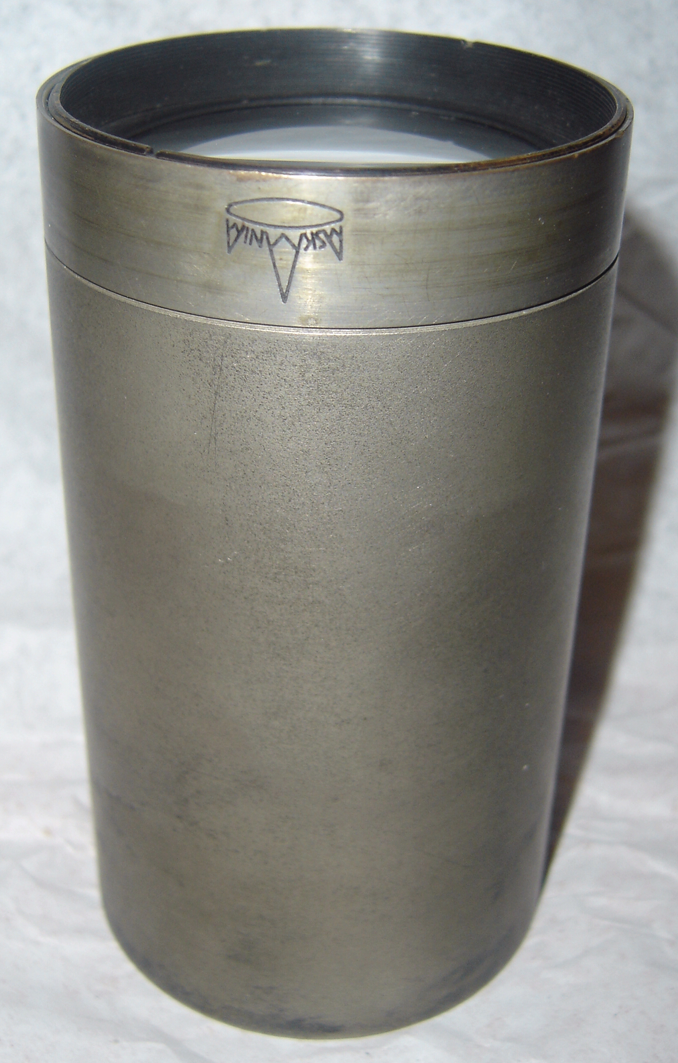
1953 saw the development of wide screen films using special lenses for filming and projection. The images on these films utilized a more squarish aspect ratio (1.18:1) in order to accommodate both magnetic and optical tracks. The wide image is compressed horizontally in half onto the film in the camera using additional cylindrical elements within the lens, with a corresponding lens used in the projector to expand the image to the wide screen. This technique is called anamorphic projection and various implementations have been marketed under several brand names, including CinemaScope, Panavision and Superscope, with Technirama implementing a slightly different anamorphic technique using vertical expansion to the film rather than horizontal compression. Large format anamorphic processes included and Ultra Panavision and Camera 65 (which was renamed Ultra panavision in the early 60s).
Fish eye with dome
The IMAX dome projection method (called "OMNIMAX") uses 70 mm film running sideways through the projector to maximize the image area and extreme wide angle lenses to obtain an almost hemispherical image. The field of view is tilted, as is the projection hemisphere, so one may view a portion of the ground in the foreground. Owing to the great area covered by the picture it is not as bright as seen with flat screen projection, but the immersive qualities are quite convincing. While there are not many theaters capable of displaying this format there are regular productions in the fields of nature, travel, science, and history, and productions may be viewed in most large urban regions. These dome theaters are mostly located in large and prosperous science and technology museums.
Wide and deep flat screen
The IMAX flat screen system uses large format film, a wide and deep screen, and close and quite steep "stadium" seating. The effect is to fill the visual field to a greater degree than is possible with conventional wide screen systems. Like the IMAX dome, this is found in major urban areas, but unlike the dome system it is practical to reformat existing movie releases to this method. Also, the geometry of the theater and screen are more amenable to inclusion within a newly constructed but otherwise conventional multiple theater complex than is the dome style theater.
Multiple cameras and projectors
One wide screen development during the 1950s used non-anamorphic projection, but used three side by side synchronised projectors. Called Cinerama, the images were projected onto an extremely wide, curved screen. Some seams were said to be visible between the images but the almost complete filling of the visual field made up for this. This showed some commercial success as a limited location (only in major cities) exhibition of the technology in This is Cinerama, but the only memorable story-telling film of two made for this technology was How the West Was Won, widely seen only in its Cinemascope re-release.
While neither a technical nor a commercial success, the business model survives as implemented by the documentary production, limited release locations, and long running exhibitions of IMAX dome movies.
Three-dimensional
For techniques used to display pictures with a three-dimensional appearance, see the 3-D film article for some movie history and the stereoscopy article for technical information.
See also
- Film format
- List of film formats
- Projector (disambiguation) for a directory of projector types
- Projectionist
- Movietone sound system
References
- ^ Nowell-Smith, Geoffrey (ed.) The Oxford History of World Cinema, pp. 446–449. Oxford University Press: Oxford, 1996.
- ^ Kodak Film Notes Issue # H-50-03: Projection practices and techniques - see Manuals at http://www.film-tech.com/
External links
- Collection of restored cinema projectors and lighting by Regal Group, UK.
- Film-Tech
- American Wide Screen Museum
- The story of the DP70 - The Todd-AO Projector
- A Cinerama site
- List of 3000 movie projectors and cameras
- [2]
- "How Motion Pictures Are Projected" , August 1949, Popular Science
Photography Technical terms Angle of view · Aperture · Chromatic Aberration · Circle of confusion · Color temperature · Depth of field · Depth of focus · Exposure · Exposure compensation · Exposure value · F-number · Film format · Film speed · Focal length · Guide number · Hyperfocal distance · Metering mode · Perspective distortion · Photograph · Photographic printing · Photographic processes · Reciprocity · Red-eye effect · Science of photography · Shutter speed · Sync · Zone SystemGenres Aerial · Architectural · Black-and-white · Commercial · Cloudscape · Documentary · Erotic · Fashion · Fine art · Forensic · Glamour · High speed · Landscape · Lomography · Nature · Nude · Photojournalism · Pornography · Portrait · Post-mortem · Senior · Social documentary · Sports · Still life · Stock · Street · Vernacular · Underwater · Wedding · WildlifeTechniques Afocal photography · Bokeh · Contre-jour · Cyanotype · Fill flash · Fireworks · Harris shutter · High speed · Holography · Infrared · Kite aerial · Long exposure · Macro · Mordançage · Multiple exposure · Night · Panning · Panoramic · Photogram (Kirlian) · Print toning · Redscale · Rephotography · Rollout · Sabatier Effect · Stereoscopy · Stopping down · Sun printing · Tilt-shift · Time-lapse · Ultraviolet · VignettingComposition Diagonal Method · Framing · Geometry and symmetry · Headroom · Lead room · Rule of thirds · SimplicityEquipment Camera (Pinhole · Rangefinder · SLR · Still · TLR · Toy · View) · Darkroom (Enlarger · Safelight) · Film (Base · Format · Holder · Stock) · Filter · Flash (Beauty dish · Cucoloris · Gobo · Hot shoe · Grid · Monolight · Snoot · Softbox · Umbrella · Wireless sync) · Lens · Manufacturers · Monopod · Movie projector · Slide projector · Tripod · Tripod head · Zone plateHistory Analog photography · Autochrome Lumière · Box camera · Calotype · Camera obscura · Daguerreotype · Dufaycolor · Heliography · Painted photography backdrops · Photography and the law · Timeline of photography technology · Visual artsDigital photography Digital camera (D-SLR · Comparison of D-SLRs · Digital camera back) · Digiscoping · Digital versus film photography · Film scanner · Image sensor (CMOS APS · CCD · Three-CCD camera · Foveon X3 sensor) · Photo sharing · PixelColor photography Color · Color film (Print · Slide) · Color management (CMYK color model · Color space · Primary color · RGB color model)Photographic processing C-41 process · Cross processing · Developer · Dye coupler · E-6 process · Fixer · Gelatin silver process · Gum printing · K-14 process · Print permanence · Push processing · Stop bathList of most expensive photographs · List of photographers · Photography museums and galleries (category) · Portal · WikiProject Categories:- Film and video technology
- Projectors


Wikimedia Foundation. 2010.