- Coherer
-
The coherer was a primitive form of radio signal detector used in the first radio receivers during the wireless telegraphy era at the beginning of the twentieth century. Invented around 1890 by French scientist Édouard Branly, it consisted of a tube or capsule containing two electrodes spaced a small distance apart, with metal filings in the space between them. When a radio frequency signal was applied to the device, the initial high resistance of the filings reduced, allowing an electric current to flow through it. The coherer was a key enabling technology for radio, and was the first device used to detect radio signals in practical spark gap transmitter wireless telegraphy. It became the basis for radio reception around 1900, and remained in widespread use for about ten years. It saw commercial use again briefly in the mid 20th century in a few primitive radio-controlled toys that used spark-gap transmitter controllers.
There are two basic kinds of coherers, the original metal filings type, called the Branly coherer, and a later imperfect junction type.
Contents
Operation
Unlike modern radio stations that transmit audio (sound), the first radio transmitters transmitted Morse code, consisting of "dots" and "dashes", by on-off keying, so early radio receiving apparatus merely had to detect the presence or absence of the radio signal, not convert it into audio. The device that did this was called a detector. The coherer was the most successful of many detector devices that were tried in the early days of radio.
The basis for the operation of the coherer is that metal particles cohere (cling together) and conduct electricity much better after being subjected to radio frequency electricity. The radio signal from the antenna was applied directly across the coherer's electrodes. When the radio signal from a "dot" or "dash" came, the coherer would become conductive. The coherer's electrodes were also attached to a DC circuit powered by a battery that created a "click" sound in earphones or a telegraph sounder, or a mark on a paper tape, to record the signal. Unfortunately, the reduction in the coherer's electrical resistance persisted after the radio signal was removed. This was a problem because the coherer had to be ready immediately to receive the next "dot" or "dash". Therefore a decoherer mechanism was added, to tap the coherer, mechanically disturbing the particles to reset it to the high resistance state.
Coherence of particles by radio waves is an obscure phenomenon that is not well understood even today. Recent experiments with particle coherers seem to have confirmed the hypothesis that the particles cohere by a micro-weld phenomenon caused by radio frequency electricity flowing across the small contact area between particles.[1] The underlying principle of so-called "imperfect contact" coherers is also not well understood, but may involve a kind of tunneling of charge carriers across an imperfect junction between conductors.
Application
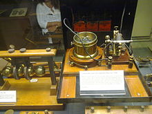
The filings coherer used in practical receivers was a glass tube, sometimes evacuated, which was about half filled with sharply cut metal filings, often part silver and part nickel. Silver electrodes made contact with the metal particles on both ends. The electrodes were slanted so the width of the gap occupied by the filings could be varied by rotating the tube about its long axis, thus adjusting its sensitivity to the prevailing conditions.
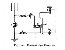
In operation, the coherer is included in two separate electrical circuits. One is the antenna-ground circuit shown in the untuned receiver circuit diagram below. The other is the battery-sounder relay circuit including battery B1 and relay R in the diagram. A radio signal from the antenna-ground circuit "turns on" the coherer, enabling current flow in the battery-sounder circuit, activating the sounder, S. The coils, L, act as RF chokes to prevent the RF signal power from leaking away through the relay circuit.
One electrode, A, of the coherer, (C, in the left diagram) is connected to the antenna and the other electrode, B, to ground. A series combination of a battery, B1, and a relay, R, is also attached to the two electrodes. When the signal from a spark gap transmitter is received, the filings tend to cling to each other, reducing the resistance of the coherer. When the coherer conducts better, battery B1 supplies enough current through the coherer to activate relay R, which connects battery B2 to the telegraph sounder S, giving an audible click. In some applications, a pair of headphones replaced the telegraph sounder, being much more sensitive to weak signals.
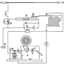
The problem of the filings continuing to cling together after the removal of the signal was solved by tapping the coherer with a small arm attached to the sounder after the arrival of each signal, shaking up the filings and raising the resistance of the coherer to the original value. This apparatus was called a decoherer. In practical implementations, the decoherer was the clapper of a door bell that was powered by the coherer current itself. This is referred to as 'decohering' the device and was subject to much innovation during the life of this component. Tesla, for example, had the tube rotating continuously along its axis, following each successive activation.
History
In 1850 Pierre Guitard found that when dusty air was electrified, the particles of dust would tend to attach themselves together in the form of strings. Again, in 1879, it was observed[2] that drops of water from a small fountain, when exposed to the influence of a charged piece of sealing-wax, would not separate into small drops, but would cohere into large ones. Temistocle Calzecchi-Onesti is thought to have performed the first experiments with a predecessor of the coherer in 1884. These phenomena had been observed for many years, but it was not until 1890 that Edouard Branly made a practical application of the principle in the form of the filings coherer as it is now known. The invention of the device is usually credited to Branly.
He began his studies in this field in 1890, being led to undertake them by observing the anomalous change in the resistance of thin metallic films when exposed to electric sparks. Platinum deposited upon glass was first employed. The effect was at first attributed to the influence of the ultraviolet light of the spark. The variations in the resistance of metals in a finely divided state were even more striking, and they were shown by Branly to be due to the action of the electrical, or Hertzian, waves of which the spark was the source. The further developments from these experiments led to the coherer. Later this simple device was employed by British radio pioneer Oliver Lodge in his researches, and formed an important part of Guglielmo Marconi's successful system of wireless telegraphy.
The coherer was replaced in receivers by the simpler and more sensitive crystal detector around 1907, and became obsolete.
Imperfect junction coherer
There are several variations of what is known as the imperfect junction coherer. The principle of operation (microwelding) suggested above for the filings coherer may be less likely to apply to this type because there is no need for decohering. The iron and mercury variation is important because the Thomasina form was used by Marconi for the first transatlantic radio message. An earlier form was invented by Jagdish Chandra Bose in 1899.[3] The device consisted of a small metallic cup containing a pool of mercury covered by a very thin insulating film of oil; above the surface a small iron disc is suspended. By means of an adjusting screw the lower edge of the disc is made to touch the oil-covered mercury with a pressure small enough not to puncture the film of oil. Its principle of operation is not well understood. The action of detection occurs when the radio frequency signal somehow breaks down the insulating film of oil, allowing the device to conduct, operating the receiving sounder wired in series. This form of coherer is self-restoring and needs no decohering.
In 1899, Bose announced the development of an "iron-mercury-iron coherer with telephone detector" in a paper presented at the Royal Society, London.[4] He also later received U.S. Patent 755,840, "Detector for electrical disturbances" (1904), for a specific electromagnetic receiver.
Limitations of coherers
Coherers had a hard time discriminating between the impulsive signals of spark-gap transmitters, and other impulsive electrical noise:[5]
All was fish that came to the coherer net, and the recorder wrote down dot and dash combinations quite impartially for legitimate signals, static disturbances, a slipping trolley several blocks away, and even the turning on and off of lights in the building. Translation of the tape frequently required a brilliant imaginationAs a simple switch registering the presence or absence of radio waves, the coherer could detect the on-off keying of wireless telegraphy transmitters, but it could not follow the complex waveforms of audio (AM) broadcasting, which began to be experimented with in the first years of the 20th century. This problem was solved by the demodulation capability enabled by Reginald Fessenden's hot wire barretter and electrolytic detector. These in turn were replaced by the crystal detector around 1906, and then around 1920 by vacuum tube technologies such as John Ambrose Fleming's thermionic diode and the triode-based regenerative detector invented by Edwin Howard Armstrong.
References
- ^ E. Falcon, B. Castaing, and M. Creyssels: Nonlinear electrical conductivity in a 1D granular medium, Laboratoire de Physique de l’Ecole Normale Sup'erieure de Lyon UMR 5672 -46 all'ee d’Italie, 69007 Lyon, France
- ^ Louis Derr, A.M., S.B., Cyclopedia of Engineering, American School of Correspondence of Armour Institute of Technology, Chicago, 1904
- ^ Bose article by Varun Aggarwal
- ^ Bondyopadhyay (1988)
- ^ quoted in Douglas, Alan (April 1981). "The crystal detector". IEEE Spectrum (New York: Inst. of Electrical and Electronic Engineers): 64. http://www.crystalradio.net/crystalplans/xximages/thecrystaldetector1.jpg. Retrieved 2010-03-14. on Stay Tuned website
See also
- Detector (radio)
- Crystal Radio
- Spark-gap transmitter
- Radio receiver
- Antique radio
- Camille Papin Tissot
External links
- "The Coherer". World of Wireless, Virtual radiomuseum.
- "Coherer / Receiver". Marconi Calling Company.
- Slaby, Adolphus, "The New Telegraphy, Recent experiments in telegraphy with sparks.". The Century Magazine. April, 1898. (Earlyradiohistory.us)
- Hirakawa Institute of Technology(Japan),"Coherer".
- "Tesla's US Patent: 613,809". ShareAPic.net.
Categories:- History of radio
- Radio electronics
- Detectors
- Electronic amplifiers
Wikimedia Foundation. 2010.


