- Crankshaft
-
 Crankshaft (red), pistons (gray) in their cylinders (blue), and flywheel (black)
The crankshaft, sometimes casually abbreviated to crank, is the part of an engine which translates reciprocating linear piston motion into rotation. To convert the reciprocating motion into rotation, the crankshaft has "crank throws" or "crankpins", additional bearing surfaces whose axis is offset from that of the crank, to which the "big ends" of the connecting rods from each cylinder attach.
It typically connects to a flywheel, to reduce the pulsation characteristic of the four-stroke cycle, and sometimes a torsional or vibrational damper at the opposite end, to reduce the torsion vibrations often caused along the length of the crankshaft by the cylinders farthest from the output end acting on the torsional elasticity of the metal.
Contents
History
Western World
Classical Antiquity
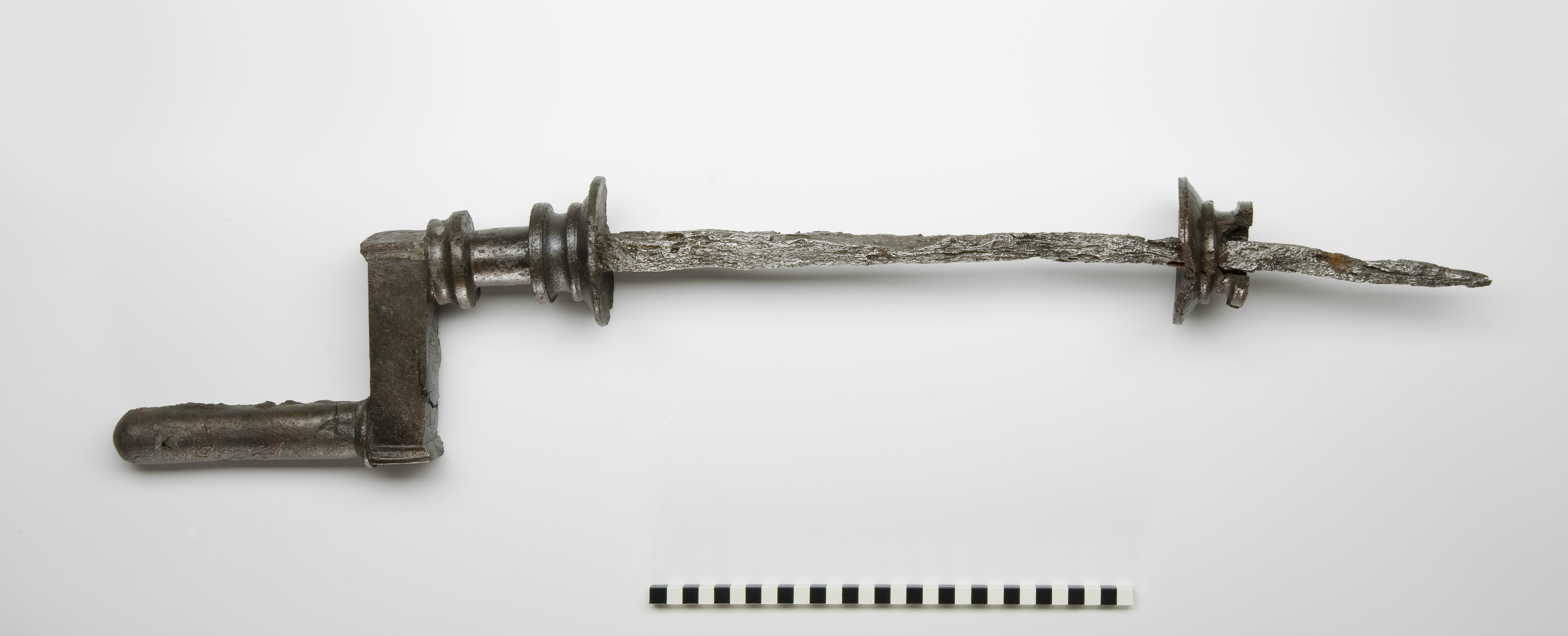
A Roman iron crankshaft of yet unknown purpose dating to the 2nd century AD was excavated in Augusta Raurica, Switzerland. The 82.5 cm long piece has fitted to one end a 15 cm long bronze handle, the other handle being lost.[2][1]
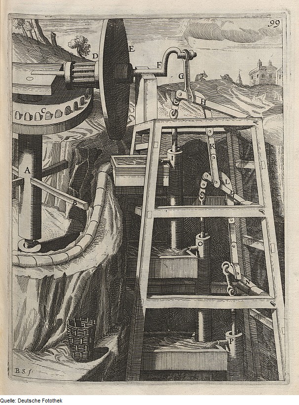
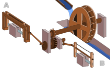 Roman Hierapolis sawmill from the 3rd century AD, the earliest known machine to combine a crank with a connecting rod.[3]
The earliest evidence, anywhere in the world, for a crank and connecting rod in a machine appears in the late Roman Hierapolis sawmill from the 3rd century AD and two Roman stone sawmills at Gerasa, Roman Syria, and Ephesus, Asia Minor (both 6th century AD).[3] On the pediment of the Hierapolis mill, a waterwheel fed by a mill race is shown powering via a gear train two frame saws which cut rectangular blocks by the way of some kind of connecting rods and, through mechanical necessity, cranks. The accompanying inscription is in Greek.[4]
The crank and connecting rod mechanisms of the other two archaeologically attested sawmills worked without a gear train.[5][6] In ancient literature, we find a reference to the workings of water-powered marble saws close to Trier, now Germany, by the late 4th century poet Ausonius;[3] about the same time, these mill types seem also to be indicated by the Christian saint Gregory of Nyssa from Anatolia, demonstrating a diversified use of water-power in many parts of the Roman Empire.[7] The three finds push back the date of the invention of the crank and connecting rod back by a full millennium;[3] for the first time, all essential components of the much later steam engine were assembled by one technological culture:
With the crank and connecting rod system, all elements for constructing a steam engine (invented in 1712) — Hero's aeolipile (generating steam power), the cylinder and piston (in metal force pumps), non-return valves (in water pumps), gearing (in water mills and clocks) — were known in Roman times.[8]Middle Ages
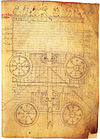
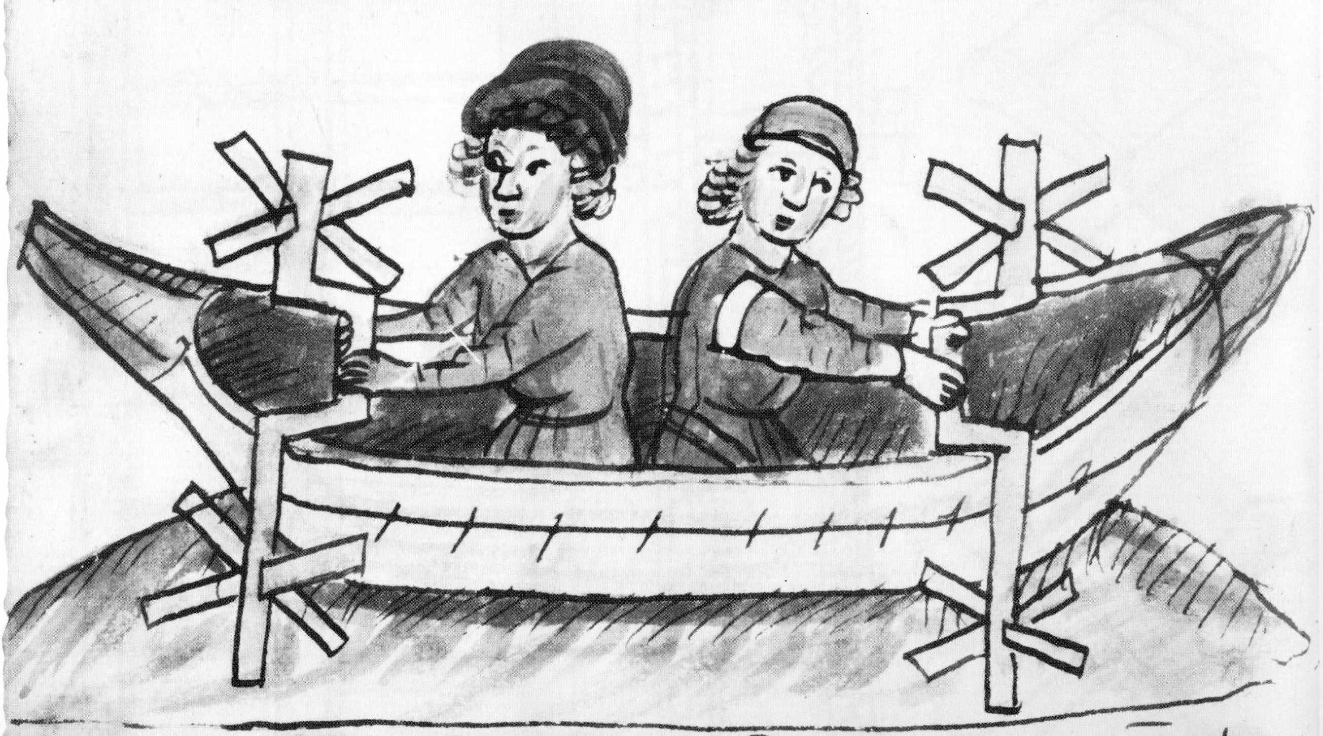
The Italian physician Guido da Vigevano (c. 1280−1349), planning for a new crusade, made illustrations for a paddle boat and war carriages that were propelled by manually turned compound cranks and gear wheels (center of image).[9] The Luttrell Psalter, dating to around 1340, describes a grindstone which was rotated by two cranks, one at each end of its axle; the geared hand-mill, operated either with one or two cranks, appeared later in the 15th century;[10]
Renaissance
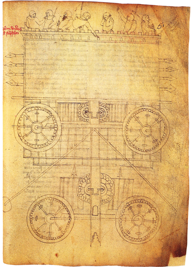
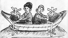 15th century paddle-wheel boat whose paddles are turned by single-throw crankshafts (Anonymous of the Hussite Wars)
The first depictions of the compound crank in the carpenter's brace appear between 1420 and 1430 in various northern European artwork.[11] The rapid adoption of the compound crank can be traced in the works of the Anonymous of the Hussite Wars, an unknown German engineer writing on the state of the military technology of his day: first, the connecting-rod, applied to cranks, reappeared, second, double compound cranks also began to be equipped with connecting-rods and third, the flywheel was employed for these cranks to get them over the 'dead-spot'.[12]
In Renaissance Italy, the earliest evidence of a compound crank and connecting-rod is found in the sketch books of Taccola, but the device is still mechanically misunderstood.[12] A sound grasp of the crank motion involved demonstrates a little later Pisanello who painted a piston-pump driven by a water-wheel and operated by two simple cranks and two connecting-rods.[12]
One of the drawings of the Anonymous of the Hussite Wars shows a boat with a pair of paddle-wheels at each end turned by men operating compound cranks (see above). The concept was much improved by the Italian Roberto Valturio in 1463, who devised a boat with five sets, where the parallel cranks are all joined to a single power source by one connecting-rod[13], an idea also taken up by his compatriot Francesco di Giorgio.[14]
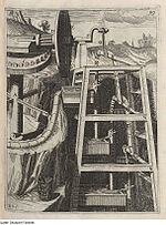
Crankshafts were also described by Konrad Kyeser (d. 1405), Leonardo da Vinci (1452–1519)[15] and a Dutch "farmer" by the name Cornelis Corneliszoon van Uitgeest in 1592. His wind-powered sawmill used a crankshaft to convert a windmill's circular motion into a back-and-forward motion powering the saw. Corneliszoon was granted a patent for his crankshaft in 1597.
From the 16th century onwards, evidence of cranks and connecting rods integrated into machine design becomes abundant in the technological treatises of the period: Agostino Ramelli's The Diverse and Artifactitious Machines of 1588 alone depicts eighteen examples, a number which rises in the Theatrum Machinarum Novum by Georg Andreas Böckler to 45 different machines, one third of the total.[16]
Middle and Far East
Al-Jazari (1136–1206) described a crank and connecting rod system in a rotating machine in two of his water-raising machines.[15] His twin-cylinder pump incorporated a crankshaft,[17] but the device was unnecessarily complex indicating that he still did not fully understand the concept of power conversion.[18] In China, the potential of the crank of converting circular motion into reciprocal one never seems to have been fully realized, and the crank was typically absent from such machines until the turn of the 20th century.[19]
Design
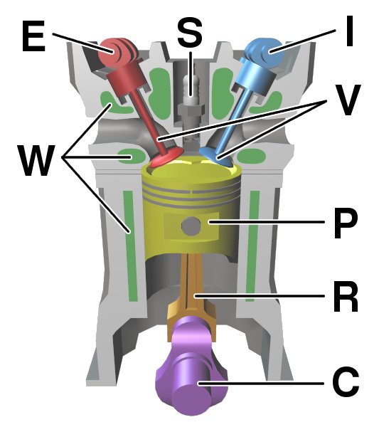
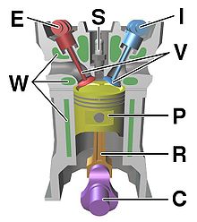 Components of a typical, four stroke cycle, DOHC piston engine. (E) Exhaust camshaft, (I) Intake camshaft, (S) Spark plug, (V) Valves, (P) Piston, (R) Connecting rod, (C) Crankshaft, (W) Water jacket for coolant flow.
Large engines are usually multicylinder to reduce pulsations from individual firing strokes, with more than one piston attached to a complex crankshaft. Many small engines, such as those found in mopeds or garden machinery, are single cylinder and use only a single piston, simplifying crankshaft design. This engine can also be built with no riveted seam.
Bearings
The crankshaft has a linear axis about which it rotates, typically with several bearing journals riding on replaceable bearings (the main bearings) held in the engine block. As the crankshaft undergoes a great deal of sideways load from each cylinder in a multicylinder engine, it must be supported by several such bearings, not just one at each end. This was a factor in the rise of V8 engines, with their shorter crankshafts, in preference to straight-8 engines. The long crankshafts of the latter suffered from an unacceptable amount of flex when engine designers began using higher compression ratios and higher rotational speeds. High performance engines often have more main bearings than their lower performance cousins for this reason.
Piston stroke
The distance the axis of the crank throws from the axis of the crankshaft determines the piston stroke measurement, and thus engine displacement. A common way to increase the low-speed torque of an engine is to increase the stroke, sometimes known as "shaft-stroking." This also increases the reciprocating vibration, however, limiting the high speed capability of the engine. In compensation, it improves the low speed operation of the engine, as the longer intake stroke through smaller valve(s) results in greater turbulence and mixing of the intake charge. For this reason, even such high speed production engines as current Honda engines are classified as "under square" or long-stroke, in that the stroke is longer than the diameter of the cylinder bore. As such, finding the proper balance between shaft-stroking speed and length will lead to better results.
Engine configuration
The configuration and number of pistons in relation to each other and the crank leads to straight, V or flat engines. The same basic engine block can be used with different crankshafts, however, to alter the firing order; for instance, the 90° V6 engine configuration, in older days sometimes derived by using six cylinders of a V8 engine with what is basically a shortened version of the V8 crankshaft, produces an engine with an inherent pulsation in the power flow due to the "missing" two cylinders. The same engine, however, can be made to provide evenly spaced power pulses by using a crankshaft with an individual crank throw for each cylinder, spaced so that the pistons are actually phased 120° apart, as in the GM 3800 engine. While production V8 engines use four crank throws spaced 90° apart, high-performance V8 engines often use a "flat" crankshaft with throws spaced 180° apart. The difference can be heard as the flat-plane crankshafts result in the engine having a smoother, higher-pitched sound than cross-plane (for example, IRL IndyCar Series compared to NASCAR Nextel Cup, or a Ferrari 355 compared to a Chevrolet Corvette). See the main article on crossplane crankshafts.
Engine balance
For some engines it is necessary to provide counterweights for the reciprocating mass of each piston and connecting rod to improve engine balance. These are typically cast as part of the crankshaft but, occasionally, are bolt-on pieces. While counter weights add a considerable amount of weight to the crankshaft, it provides a smoother running engine and allows higher RPMs to be reached.
Rotary engines
Many early aircraft engines (and a few in other applications) had the crankshaft fixed to the airframe and instead the cylinders rotated, known as a rotary engine design. Rotary engines such as the Wankel engine are referred to as pistonless rotary engines.
In the Wankel engine the rotors drive the eccentric shaft, which could be considered the equivalent of the crankshaft in a piston engine.
Construction
 Continental engine marine crankshafts, 1942
Crankshafts can be monolithic (made in a single piece) or assembled from several pieces. Monolithic crankshafts are most common, but some smaller and larger engines use assembled crankshafts.
Forging and casting
Crankshafts can be forged from a steel bar usually through roll forging or cast in ductile steel. Today more and more manufacturers tend to favor the use of forged crankshafts due to their lighter weight, more compact dimensions and better inherent dampening. With forged crankshafts, vanadium microalloyed steels are mostly used as these steels can be air cooled after reaching high strengths without additional heat treatment, with exception to the surface hardening of the bearing surfaces. The low alloy content also makes the material cheaper than high alloy steels. Carbon steels are also used, but these require additional heat treatment to reach the desired properties. Iron crankshafts are today mostly found in cheaper production engines (such as those found in the Ford Focus diesel engines) where the loads are lower. Some engines also use cast iron crankshafts for low output versions while the more expensive high output version use forged steel.
Machining
Crankshafts can also be machined out of a billet, often using a bar of high quality vacuum remelted steel. Even though the fiber flow (local inhomogeneities of the material's chemical composition generated during casting) doesn’t follow the shape of the crankshaft (which is undesirable), this is usually not a problem since higher quality steels which normally are difficult to forge can be used. These crankshafts tend to be very expensive due to the large amount of material removal which needs to be done by using lathes and milling machines, the high material cost and the additional heat treatment required. However, since no expensive tooling is required, this production method allows small production runs of crankshafts to be made without high costs.
Fatigue strength
The fatigue strength of crankshafts is usually increased by using a radius at the ends of each main and crankpin bearing. The radius itself reduces the stress in these critical areas, but since the radius in most cases are rolled, this also leaves some compressive residual stress in the surface which prevents cracks from forming.
Hardening
Most production crankshafts use induction hardened bearing surfaces since that method gives good results with low costs. It also allows the crankshaft to be reground without having to redo the hardening. But high performance crankshafts, billet crankshafts in particular, tend to use nitridization instead. Nitridization is slower and thereby more costly, and in addition it puts certain demands on the alloying metals in the steel, in order to be able to create stable nitrides. The advantage with nitridization is that it can be done at low temperatures, it produces a very hard surface and the process will leave some compressive residual stress in the surface which is good for the fatigue properties of the crankshaft. The low temperature during treatment is advantageous in that it doesn’t have any negative effects on the steel, such as annealing. With crankshafts that operate on roller bearings, the use of carburization tends to be favored due to the high Hertzian contact stresses in such an application. Like nitriding, carburization also leaves some compressive residual stresses in the surface.
Counterweights
Some expensive, high performance crankshafts also use heavy-metal counterweights to make the crankshaft more compact. The heavy-metal used is most often a tungsten alloy but depleted uranium has also been used. A cheaper option is to use lead, but compared with tungsten its density is much lower.
Stress on crankshafts
The shaft is subjected to various forces but generally needs to be analysed in two positions. Firstly, failure may occur at the position of maximum bending; this may be at the centre of the crank or at either end. In such a condition the failure is due to bending and the pressure in the cylinder is maximal. Second, the crank may fail due to twisting, so the conrod needs to be checked for shear at the position of maximal twisting. The pressure at this position is the maximal pressure, but only a fraction of maximal pressure.
See also
- Crankcase, the housing that surrounds the crankshaft
- Bicycle crankset
- Crank (mechanism)
- Brace (tool)
- Controlled Combustion Engine
- Piston motion equations
- Hudson Motor Car Company, balanced crankshaft in 1916 allowed higher RPM & more power
- Camshaft
- Cam
References
- ^ a b Schiöler 2009, pp. 113f.
- ^ Laur-Belart 1988, p. 51–52, 56, fig. 42
- ^ a b c d Ritti, Grewe & Kessener 2007, p. 161:
Because of the findings at Ephesus and Gerasa the invention of the crank and connecting rod system has had to be redated from the 13th to the 6th c; now the Hierapolis relief takes it back another three centuries, which confirms that water-powered stone saw mills were indeed in use when Ausonius wrote his Mosella.
- ^ Ritti, Grewe & Kessener 2007, pp. 139–141
- ^ Ritti, Grewe & Kessener 2007, pp. 149–153
- ^ Mangartz 2010
- ^ Wilson 2002, p. 16
- ^ Ritti, Grewe & Kessener 2007, p. 156, fn. 74
- ^ Hall 1979, p. 80
- ^ White, Jr. 1962, p. 111
- ^ White, Jr. 1962, p. 112
- ^ a b c White, Jr. 1962, p. 113
- ^ See illustration here (top): http://www.cervantesvirtual.com/s3/BVMC_OBRAS/fff/50e/6e8/2b1/11d/fac/c70/021/85c/e60/64/mimes/fff50e6e-82b1-11df-acc7-002185ce6064_415.htm
- ^ White, Jr. 1962, p. 114
- ^ a b Ahmad Y Hassan. The Crank-Connecting Rod System in a Continuously Rotating Machine.
- ^ White, Jr. 1962, p. 172
- ^ Sally Ganchy, Sarah Gancher (2009), Islam and Science, Medicine, and Technology, The Rosen Publishing Group, p. 41, ISBN 1435850661
- ^ White, Jr. 1962, p. 170:
However, that al-Jazari did not entirely grasp the meaning of the crank for joining reciprocating with rotary motion is shown by his extraordinarily complex pump powered through a cog-wheel mounted eccentrically on its axle.
- ^ White, Jr. 1962, p. 104:
Yet a student of the Chinese technology of the early twentieth century remarks that even a generation ago the Chinese had not 'reached that stage where continuous rotary motion is substituted for reciprocating motion in technical contrivances such as the drill, lathe, saw, etc. To take this step familiarity with the crank is necessary. The crank in its simple rudimentary form we find in the [modern] Chinese windlass, which use of the device, however, has apparently not given the impulse to change reciprocating into circular motion in other contrivances'. In China the crank was known, but remained dormant for at least nineteen centuries, its explosive potential for applied mechanics being unrecognized and unexploited.
Sources
- Hall, Bert S. (1979), The Technological Illustrations of the So-Called "Anonymous of the Hussite Wars". Codex Latinus Monacensis 197, Part 1, Wiesbaden: Dr. Ludwig Reichert Verlag, ISBN 3-920153-93-6
- al-Hassan, Ahmad Y.; Hill, Donald R. (1992), Islamic Technology. An Illustrated History, Cambridge University Press, ISBN 0-521-422396
- Laur-Belart, Rudolf (1988), Führer durch Augusta Raurica (5th ed.), Augst
- Mangartz, Fritz (2010), Die byzantinische Steinsäge von Ephesos. Baubefund, Rekonstruktion, Architekturteile, Monographs of the RGZM, 86, Mainz: Römisch-Germanisches Zentralmuseum, ISBN 978-3-88467-149-8
- White, Jr., Lynn (1962), Medieval Technology and Social Change, Oxford: At the Clarendon Press
- Ritti, Tullia; Grewe, Klaus; Kessener, Paul (2007), "A Relief of a Water-powered Stone Saw Mill on a Sarcophagus at Hierapolis and its Implications", Journal of Roman Archaeology 20: 138–163
- Schiöler, Thorkild (2009), "Die Kurbelwelle von Augst und die römische Steinsägemühle", Helvetia Archaeologica 40 (159/160): 113–124
- Wilson, Andrew (2002), "Machines, Power and the Ancient Economy", The Journal of Roman Studies 92: 1–32
External links
- Grewe, Klaus (2009), "Die Reliefdarstellung einer antiken Steinsägemaschine aus Hierapolis in Phrygien und ihre Bedeutung für die Technikgeschichte. Internationale Konferenz 13.−16. Juni 2007 in Istanbul", in Bachmann, Martin (in German), Bautechnik im antiken und vorantiken Kleinasien, Byzas, 9, Istanbul: Ege Yayınları/Zero Prod. Ltd., pp. 429–454, ISBN 978-975-807-223-1, http://www.freundeskreis-roemerkanal.de/Text/BAUTECHNIK%20IM%20ANTIKEN%20UND.pdf
Reciprocating engines and configurations Type Stroke cycles Engine
configurationsI2 · I3 · I4 · I5 · I6 · I7 · I8 · I9 · I10 · I12 · I14F2 · F4 · F6 · F8 · F12 · F16Other inlineComponents Cylinder head porting · Corliss · Intake · Exhaust · Multi · Overhead · Piston · Piston (steam engine) · Poppet · Side · Sleeve · Slide · Rotary valve · Variable valve timing · Camless · DesmodromicCam · Camshaft · Overhead camshaft · Connecting rod · Crank · Crank substitute · Crankshaft · Scotch Yoke · Swashplate · Rhombic driveOtherCategories:- Piston engine configurations
- Linkages
- Engine technology
- Piston engines
- Engine components


Wikimedia Foundation. 2010.