- AC power
-
This article deals with power in AC systems. See Mains electricity for information on utility-supplied AC power.
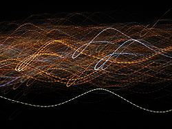 Usually hidden from the unaided eye, the blinking of (non-incandescent) lighting powered by AC mains is revealed in this motion-blurred long exposure of city lights. Light is emitted twice each cycle.
Power in an electric circuit is the rate of flow of energy past a given point of the circuit. In alternating current circuits, energy storage elements such as inductance and capacitance may result in periodic reversals of the direction of energy flow. The portion of power that, averaged over a complete cycle of the AC waveform, results in net transfer of energy in one direction is known as real power. The portion of power due to stored energy, which returns to the source in each cycle, is known as reactive power.
Contents
Real, reactive, and apparent powers
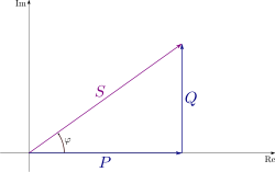 The complex power is the vector sum of real and reactive power. The apparent power is the magnitude of the complex power.
Real power (P)
Reactive power (Q)
Complex power (S)
Apparent Power (|S|)
Phase of Current (φ)In a simple alternating current (AC) circuit consisting of a source and a linear load, both the current and voltage are sinusoidal. If the load is purely resistive, the two quantities reverse their polarity at the same time. At every instant the product of voltage and current is positive, indicating that the direction of energy flow does not reverse. In this case, only real power is transferred.
If the loads are purely reactive, then the voltage and current are 90 degrees out of phase. For half of each cycle, the product of voltage and current is positive, but on the other half of the cycle, the product is negative, indicating that on average, exactly as much energy flows toward the load as flows back. There is no net energy flow over one cycle. In this case, only reactive energy flows—there is no net transfer of energy to the load.
Practical loads have resistance, inductance, and capacitance, so both real and reactive power will flow to real loads. Power engineers measure apparent power as the magnitude of the vector sum of real and reactive power. Apparent power is the product of the root-mean-square of voltage and current.
Engineers care about apparent power, because even though the current associated with reactive power does no work at the load, it heats the wires, wasting energy. Conductors, transformers and generators must be sized to carry the total current, not just the current that does useful work.
Another consequence is that adding the apparent power for two loads will not accurately give the total apparent power unless they have the same displacement between current and voltage (the same power factor).
Conventionally, capacitors are considered to generate reactive power and inductors to consume it. If a capacitor and an inductor are placed in parallel, then the currents flowing through the inductor and the capacitor tend to cancel rather than add. This is the fundamental mechanism for controlling the power factor in electric power transmission; capacitors (or inductors) are inserted in a circuit to partially cancel reactive power 'consumed' by the load.
Engineers use the following terms to describe energy flow in a system (and assign each of them a different unit to differentiate between them):
- Real power (P) or active power[1]: watt [W]
- Reactive power (Q): volt-ampere reactive [VAR]
- Complex power (S): volt-ampere [VA]
- Apparent Power (|S|), that is, the absolute value of complex power S: volt-ampere [VA]
- Phase of Voltage Relative to Current (φ), the angle of difference (in degrees) between voltage and current; Current lagging Voltage (Quadrant I Vector), Current leading voltage (Quadrant IV Vector)
In the diagram, P is the real power, Q is the reactive power (in this case positive), S is the complex power and the length of S is the apparent power.
Reactive power does not transfer energy, so it is represented as the imaginary axis of the vector diagram. Real power moves energy, so it is the real axis.
The unit for all forms of power is the watt (symbol: W), but this unit is generally reserved for real power. Apparent power is conventionally expressed in volt-amperes (VA) since it is the product of rms voltage and rms current. The unit for reactive power is expressed as var, which stands for volt-amperes reactive. Since reactive power transfers no net energy to the load, it is sometimes called "wattless" power. It does, however, serve an important function in electrical grids and its lack has been cited as a significant factor in the Northeast Blackout of 2003.[2]
Understanding the relationship between these three quantities lies at the heart of understanding power engineering. The mathematical relationship among them can be represented by vectors or expressed using complex numbers, S = P + jQ (where j is the imaginary unit).
Power factor
Main article: Power factorThe ratio between real power and apparent power in a circuit is called the power factor. It's a practical measure of the efficiency of a power distribution system. For two systems transmitting the same amount of real power, the system with the lower power factor will have higher circulating currents due to energy that returns to the source from energy storage in the load. These higher currents produce higher losses and reduce overall transmission efficiency. A lower power factor circuit will have a higher apparent power and higher losses for the same amount of real power.
The power factor is one when the voltage and current are in phase. It is zero when the current leads or lags the voltage by 90 degrees. Power factors are usually stated as "leading" or "lagging" to show the sign of the phase angle of current with respect to voltage.
Purely capacitive circuits cause reactive power with the current waveform leading the voltage wave by 90 degrees, while purely inductive circuits cause reactive power with the current waveform lagging the voltage waveform by 90 degrees. The result of this is that capacitive and inductive circuit elements tend to cancel each other out.
Where the waveforms are purely sinusoidal, the power factor is the cosine of the phase angle (φ) between the current and voltage sinusoid waveforms. Equipment data sheets and nameplates often will abbreviate power factor as "cos ϕ" for this reason.
Example: The real power is 700 W and the phase angle between voltage and current is 45.6°. The power factor is cos(45.6°) = 0.700. The apparent power is then: 700 W / cos(45.6°) = 1000 VA.[3]
Reactive power
Main article: Volt-ampere reactiveReactive power flow on the alternating current transmission system is needed to support the transfer of real power over the network. In alternating current circuits energy is stored temporarily in inductive and capacitive elements, which can result in the periodic reversal of the direction of energy flow. The portion of power flow remaining after being averaged over a complete AC waveform is the real power, which is energy that can be used to do work (for example overcome friction in a motor, or heat an element). On the other hand the portion of power flow that is temporarily stored in the form of electric or magnetic fields, due to inductive and capacitive network elements, and returned to source is known as the reactive power.
AC connected devices that store energy in the form of a magnetic field include inductive devices called reactors, which consist of a large coil of wire. When a voltage is initially placed across the coil a magnetic field builds up, and it takes a period of time for the current to reach full value. This causes the current to lag the voltage in phase, and hence these devices are said to absorb reactive power.
A capacitor is an AC device that stores energy in the form of an electric field. When current is driven through the capacitor, it takes a period of time for charge to build up to produce the full voltage difference. On an AC network the voltage across a capacitor is always changing – the capacitor will oppose this change causing the voltage to lag behind the current. In other words the current leads the voltage in phase, and hence these devices are said to generate reactive power.
Energy stored in capacitive or inductive elements of the network give rise to reactive power flow. Reactive power flow strongly influences the voltage levels across the network. Voltage levels and reactive power flow must be carefully controlled to allow a power system to be operated within acceptable limits.
Reactive power control
Transmission connected generators are generally required to support reactive power flow. For example on the Great Britain transmission system generators are required by the Grid Code Requirements to supply their rated power between the limits of 0.85 power factor lagging and 0.95 power factor leading at the designated terminals. The system operator will perform switching actions to maintain a secure and economical voltage profile while maintaining a reactive power balance equation:
Generator_MVARs + System_gain + Shunt_capacitors = MVAR_Demand + Reactive_losses + Shunt_reactors
The ‘System gain’ is an important source of reactive power in the above power balance equation, which is generated by the capacitive nature of the transmission network itself. By making decisive switching actions in the early morning before the demand increases, the system gain can be maximized early on, helping to secure the system for the whole day.
To balance the equation some pre-fault reactive generator use will be required. Other sources of reactive power that will also be used include shunt capacitors, shunt reactors, Static VAR Compensators and voltage control circuits.
Unbalanced polyphase systems
While real power and reactive power are well defined in any system, the definition of apparent power for unbalanced polyphase systems is considered to be one of the most controversial topics in power engineering. Originally, apparent power arose merely as a figure of merit. Major delineations of the concept are attributed to Stanley's Phenomena of Retardation in the Induction Coil (1888) and Steinmetz's Theoretical Elements of Engineering (1915). However, with the development of three phase power distribution, it became clear that the definition of apparent power and the power factor could not be applied to unbalanced polyphase systems. In 1920, a "Special Joint Committee of the AIEE and the National Electric Light Association" met to resolve the issue. They considered two definitions:
that is, the quotient of the sums of the real powers for each phase over the sum of the apparent power for each phase.
that is, the quotient of the sums of the real powers for each phase over the magnitude of the sum of the complex powers for each phase.
The 1920 committee found no consensus and the topic continued to dominate discussions. In 1930 another committee formed and once again failed to resolve the question. The transcripts of their discussions are the lengthiest and most controversial ever published by the AIEE (Emanuel, 1993). Further resolution of this debate did not come until the late 1990s.
Basic calculations using real numbers
A perfect resistor stores no energy, so current and voltage are in phase. Therefore there is no reactive power and P = S. Therefore for a perfect resistor

For a perfect capacitor or inductor there is no net power transfer, so all power is reactive. Therefore for a perfect capacitor or inductor:


Where X is the reactance of the capacitor or inductor.
If X is defined as being positive for an inductor and negative for a capacitor then we can remove the modulus signs from Q and X and get

Multiple frequency systems
Since an RMS value can be calculated for any waveform, apparent power can be calculated from this.
For real power it would at first appear that we would have to calculate loads of product terms and average all of them. However if we look at one of these product terms in more detail we come to a very interesting result.


however the time average of a function of the form cos(ωt+k) is zero provided that ω is nonzero. Therefore the only product terms that have a nonzero average are those where the frequency of voltage and current match. In other words it is possible to calculate real (average) power by simply treating each frequency separately and adding up the answers.
Furthermore, if we assume the voltage of the mains supply is a single frequency (which it usually is), this shows that harmonic currents are a bad thing. They will increase the rms current (since there will be non-zero terms added) and therefore apparent power, but they will have no effect on the real power transferred. Hence, harmonic currents will reduce the power factor.
Harmonic currents can be reduced by a filter placed at the input of the device. Typically this will consist of either just a capacitor (relying on parasitic resistance and inductance in the supply) or a capacitor-inductor network. An active power factor correction circuit at the input would generally reduce the harmonic currents further and maintain the power factor closer to unity.
See also
References
- ^ IEEE 100 : the authoritative dictionary of IEEE standards terms.-7th ed. ISBN 0-7381-2601-2, page 23
- ^ "August 14, 2003 Outage - Sequence of Events". FERC. 2003-09-12. Archived from the original on 2007-10-20. http://web.archive.org/web/20071020070028/http://www.ferc.gov/industries/electric/indus-act/blackout/09-12-03-blackout-sum.pdf. Retrieved 2008-02-18.
- ^ "AC power calculation". http://74.125.77.132/search?q=cache:LOdT-N4UkNUJ:encon.fke.utm.my/courses/see1023/AC_CircuitAnaysis2.ppt. 091123 encon.fke.utm.my (google cache)
Electricity generation Concepts Availability factor · Baseload · Black start · Capacity factor · Demand factor · Demand management · EROEI · Grid storage · Intermittency · Load following · Nameplate capacity · Peak demand · Repowering · Spark spreadSources Technology AC power · Cogeneration · Combined cycle · Cooling tower · Induction generator · Micro CHP · Microgeneration · Rankine cycle · Three-phase electric power · Virtual power plantDistribution Policies Carbon offset · Coal phase out · Ecotax · Energy subsidies · Feed-in tariff · Net metering · Pigovian tax · Renewable Energy Certificates · Renewable energy payments · Renewable energy policyCategories: Electric power distribution · Electricity economics · Power station technology · Portals: Energy · Sustainable development Categories:


Wikimedia Foundation. 2010.