- Communications-based train control
-
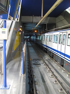
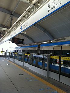
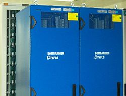
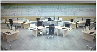
World´s busiest metros are choosing radio-based CBTC systems to improve the operation (in the case of these images, two lines equipped with the Bombardier´s CBTC solution CITYFLO 650])
Communications-Based Train Control (CBTC) is a railway signalling system that makes use of the telecommunications between the train and track equipment for the traffic management and infrastructure control. By means of the CBTC systems, the exact position of a train is known more accurately than with the traditional signalling systems. This results in a more efficient and safe way to manage the railway traffic. Metros (and other railway systems) are able to improve headways while maintaining or even improving also the safety.
A CBTC system is a “continuous, automatic train control system utilizing high-resolution train location determination, independent of track circuits; continuous, high-capacity, bidirectional train-to-wayside data communications; and trainborne and wayside processors capable of implementing Automatic Train Protection (ATP) functions, as well as optional Automatic Train Operation (ATO) and Automatic Train Supervision (ATS) functions.”, as defined in the IEEE 1474 standard.[1]
Contents
Background and origin
City and population growth increases the need for mass transit transport and signalling systems need to evolve and adapt to safely meet this increase in demand and traffic capacity. As a result of this operators are now focused on maximising train line capacity. The main objective of CBTC is to increase capacity by safely reducing the time interval (headway) between trains travelling along the line.
Traditional legacy signalling systems are historically based in the detection of the trains in discrete sections of the track called ‘blocks’. Each block is protected by signals that prevent a train entering an occupied block. Since every block is fixed by the infrastructure, these systems are referred to as fixed block systems.
Unlike the traditional fixed block systems, in the modern moving block CBTC systems the protected section for each train is not statically defined by the infrastructure (except for the virtual block technology, with operating appearance of a moving block but still constrained by physical blocks). Besides, the trains themselves are continuously communicating their exact position to the equipment in the track by means of a bi-directional link, either inductive loop as is used by Dubai Metro, or radio communication.
The advent of digital radio communication technology during the early 90s, encouraged the signalling industry on both sides of the Atlantic to explore using radio communication as a viable means of track to train communication, mainly due to its increased capacity and reduced costs compared to the existing transmission loop-based systems, and this is how CBTC systems started to evolve.[2]
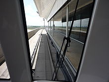
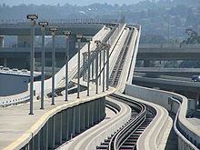 SFO AirTrain, in San Francisco Airport, was the first radio-based CBTC system deployment in the world
As a result, Bombardier opened the world’s first radio-based CBTC system at San Francisco airport´s Automated People Mover (APM) in February 2003. A few months later, in June 2003, Alstom introduced the railway application of its radio technology on the Singapore North East Line. Previously, CBTC has its former origins in the loop based systems developed by Alcatel SEL (now Thales) for the Bombardier Automated Rapid Transit (ART) systems in Canada during the mid 1980s. These systems, which were also referred to as Transmission-Based Train Control (TBTC), made use of inductive loop transmission techniques for track to train communication, introducing an alternative to track circuit based communication. This technology, operating in the 30-60 KHz frequency range to communicate trains and wayside equipment, was widely adopted by the metro operators in spite of some electromagnetic compatibility (EMC) issues, as well as other installation and maintenance concerns.
As every new application of any technology, some problems arose at the beginning mainly due to compatibility and interoperability aspects.[3][4] However, there have been relevant improvements since then, and currently the reliability of the radio-based communication systems has grown significantly.
Moreover, it is important to highlight that not all the systems using radio communication technology are considered to be CBTC systems. So, for clarity and to keep in line with the state-of-the-art solutions for operator´s requirements,[4] this article only covers the latest moving block principle based (either true moving block or virtual block, so not dependent on track-based detection of the trains)[1] CBTC solutions that make use of the radio communications.
Main features
CBTC and moving block
CBTC systems are modern railway signalling systems that can mainly be used in urban railway lines (either light or heavy) and APMs, although it could also be deployed on commuter lines. For main lines, a similar system might be the European Railway Traffic Management System ERTMS Level 3 (not yet fully defined). In the modern CBTC systems the trains continuously calculate and communicate their status via radio to the wayside equipment distributed along the line. This status includes, among others parameters, the exact position, speed, travel direction and braking distance. This information allows calculation of the area potentially occupied by the train on the track. It also enables the wayside equipment to define the points on the line that must never be passed by the other trains on the same track. These points are communicated to make the trains automatically and continuously adjust their speed while maintaining the safety and comfort (jerk) requirements. So, the trains continuously receive information regarding the distance to the preceding train and are then able to adjust their safety distance accordingly.
 Safety distance between trains in fixed block and moving block signalling systems
From the signalling system perspective, the first figure shows the total occupancy of the leading train by including the whole blocks which the train is located on. This is due to the fact that it is impossible for the system to know exactly where the train actually is within these blocks. Therefore, the fixed block system will only allow the following train to move up to the last unoccupied block's border.
On the other hand, in a moving block system as shown in the second figure, the train position and its braking curve is continuously calculated by the trains, and then communicated via radio to the wayside equipment. Thus, the wayside equipment is able to establish protected areas, each one called Limit of Movement Authority (LMA), up to the nearest obstacle (in the figure the tail of the train in front).
It is important to mention that the occupancy calculated in these systems must include a safety margin for location uncertainty (in yellow in the figure) added to the length of the train. Both of them form what is usually called ‘Footprint’. This safety margin depends on the accuracy of the odometry system in the train.
Therefore, the CBTC systems based on moving block allows to reduce the safety distance between two consecutive trains. This distance is varying according to the continuous updates of the train location and speed, maintaining the safety requirements. This results in a reduced headway between consecutive trains and an increased transport capacity.
Levels of automation
Modern CBTC systems allow different levels of automation or Grades of Automation, GoA, as defined and classified in the IEC 62290-1.[5] In fact, CBTC is not a synonym for “driverless” or “automated trains” although it is considered as a basic technology for this purpose.
The grades of automation available range from a manual protected operation, GoA 1 (usually applied as a fallback operation mode) to the fully automated operation, GoA 4 (Unattended Train Operation, UTO). Intermediate operation modes comprise semi-automated GoA 2 (Semi-automated Operation Mode, STO) or driverless GoA 3 (Driverless Train Operation, DTO).[6] The latter operates without a driver in the cabin, but requires an attendant to face degraded modes of operation as well as guide the passengers in the case of emergencies. The higher the GoA, the higher the safety, functionality and performance levels must be.[6]
Main applications
CBTC systems allow optimal use of the railway infrastructure as well as achieving maximum capacity and minimum headway between operating trains, while maintaining the safety requirements. These systems are suitable for the new highly demanding urban lines, but also to be overlaid on existing lines in order to improve their performance.[7]
Of course, in the case of upgrading existing lines the design, installation, test and commissioning stages are much more critical. This is mainly due to the challenge of deploying the overlying system without disrupting the revenue service.[8]
Main benefits
The evolution of the technology and the experience gained in operation over the last 30 years means that modern CBTC systems are more reliable and less prone to failure than older train control systems. CBTC systems normally have less wayside equipment and their diagnostic and monitoring tools have been improved, which makes them easier to implement and, more importantly, easier to maintain.[6]
CBTC technology is evolving, making use of the latest techniques and components to offer more compact systems and simpler architectures. For instance, with the advent of modern electronics it has been possible to build in redundancy so that single failures do not adversely impact operational availability.
Moreover, these systems offer complete flexibility in terms of operational schedules or timetables, enabling urban rail operators to respond to the specific traffic demand more swiftly and efficiently and to solve traffic congestion problems. In fact, automatic operation systems have the potential to significantly reduce the headway and improve the traffic capacity compared to manual driving systems.[9][10]
Finally, it is important to mention that the CBTC systems have proven to be more energy efficient than traditional manually-driven systems.[6] The use of new functionalities, such as automatic driving strategies or a better adaptation of the transport offer to the actual demand, allows significant energy savings reducing the power consumption.
Architecture
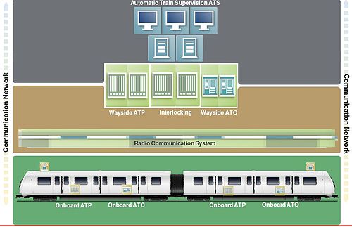
The typical architecture of a modern CBTC system comprises the following main subsystems:
- Wayside equipment, which includes the interlocking and the subsystems controlling every zone in the line or network (typically containing the wayside ATP and ATO functionalities). Depending on the suppliers, the architectures may be centralized of distributed. The control of the system is performed from a central command ATS, though local control subsystems may be also included as a fallback.
- CBTC onboard equipment, including ATP and ATO subsystems in the vehicles.
- Train to wayside communication subsystem, currently based on radio links.
Thus, although a CBTC architecture is always depending on the supplier and its technical approach, the following logical components may be found generally in a typical CBTC architecture:
-
-
-
- Onboard ATP system. This subsystem is in charge of the continuous control of the train speed according to the safety profile, and applying the brake if it is necessary. It is also in charge of the communication with the wayside ATP subsystem in order to exchange the information needed for a safe operation (sending speed and braking distance, and receiving the limit of movement authority for a safe operation).
-
-
-
-
-
- Onboard ATO system. It is responsible for the automatic control of the traction and braking effort in order to keep the train under the threshold established by the ATP subsystem. Its main task is either to facilitate the driver or attendant functions, or even to operate the train in a fully automatic mode while maintaining the traffic regulation targets and passenger comfort. It also allows the selection of different automatic driving strategies to adapt the runtime or even reduce the power consumption.
-
-
-
-
-
- Wayside ATP system. This subsystem undertakes the management of all the communications with the trains in its area. Additionally, it calculates the limits of movement authority that every train must respect while operating in the mentioned area. This task is therefore critical for the operation safety.
-
-
-
-
-
- Wayside ATO system. It is in charge of controlling the destination and regulation targets of every train. The wayside ATO functionality provides all the trains in the system with their destination as well as with other data such as the dwell time in the stations. Additionally, it may also perform auxiliary and non-safety related tasks including for instance alarm/event communication and management, or handling skip/hold station commands.
-
-
-
-
-
- Communication system.The CBTC systems integrate a digital networked radio system by means of antennas or leaky feeder cable for the bi-directional communication between the track equipment and the trains. The 2,4GHz band is commonly used in these systems (same as WiFi), though other alternative frequencies such as 900MHz (US), 5,8GHz or other licensed bands may be used as well.
-
-
-
-
-
- ATS system. The ATS system is commonly integrated within most of the CBTC solutions. Its main task is to act as the interface between the operator and the system, managing the traffic according to the specific regulation criteria. Other tasks may include the event and alarm management as well as acting as the interface with external systems.
-
-
-
-
-
- Interlocking system. When needed as an independent subsystem (for instance as a fallback system), it will be in charge of the vital control of the trackside objects such as switches or signals, as well as other related functionality. In the case of simpler networks or lines, the functionality of the interlocking may be integrated into the wayside ATP system.
-
-
Main suppliers
Nowadays, main radio-based CBTC suppliers are, in alphabetical order:
Projects
CBTC technology has been (and is being) successfully implemented for a variety of applications as shown in the figure below (mid 2011). They range from some implementations with short track, limited numbers of vehicles and few operating modes (such as the airport APMs in San Francisco or Washington), to complex overlays on existing railway networks carrying more than a million passengers each day and with more than 100 trains (such as lines 1 and 6 in Metro de Madrid, line 3 in Shenzhen Metro, some lines in Paris Metro and Beijing Metro, or the Sub-Surface network SSR in London Underground]).[11]
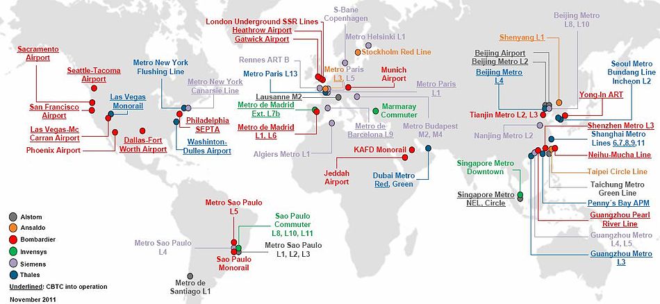 Radio-based CBTC moving block projects around the world. Projects are classified with colours depending on the supplier; those underlined are already into CBTC operation[note 1]
Despite the difficulty, the table below tries to summarize and reference the main radio-based CBTC systems deployed around the world as well as those ongoing projects being developed. Besides, the table distinguishes between the implementations performed over existing and operative systems (brownfield) and those undertaken on completely new lines (Greenfield).We must take into account that the transmission technology based on inductive loops (referred to as TBTC in this article) is now being less and less used. That is why, for clarity, all the projects listed here are modern radio-based CBTC systems making use of the moving block concept as described above.
CBTC project list around the world (radio-based and moving block principle)[note 2][note 3] Location Line/System Supplier Solution Commissioning Km No. of trains Comments San Francisco Airport AirTrain APM BOMBARDIER CITYFLO 650 2003 5 38 Greenfield, UTO Singapore Metro North-East Line ALSTOM Urbalis 2003 20 25 UTO Seattle-Tacoma Airport Satellite Transit System APM BOMBARDIER CITYFLO 650 2003 3 22 Brownfield, UTO Las Vegas Monorail THALES SelTrac RF 2004 6 36 Greenfield, UTO Wuhan_Metro 1 THALES SelTrac 2004 27 32 Dallas-Fortworth Airport DFW Skylink APM BOMBARDIER CITYFLO 650 2005 10 64 Greenfield, UTO Hong Kong Disneyland Penny´s Bay Line THALES SelTrac RF 2005 3 2 Greenfield, UTO Lausanne Metro M2 ALSTOM Urbalis 2008 6 ? UTO Beijing Airport Express ALSTOM Urbalis 2008 28 10 Greenfield, UTO Beijing Metro 2 ALSTOM Urbalis 2008 23 48 Metro de Madrid 1, 6 BOMBARDIER CITYFLO 650 2008 48 124 Brownfield, STO Las Vegas-McCarran Airport McCarran Airport APM BOMBARDIER CITYFLO 650 2008 2 6 Brownfield, UTO London Heathrow Airport Heathrow APM BOMBARDIER CITYFLO 650 2008 1 9 Greenfield, UTO Metro de Barcelona 9 SIEMENS Trainguard MT CBTC 2009 46 50 Greenfield, UTO New York City Transit Canarsie Line SIEMENS Trainguard MT CBTC 2009 17 53 Brownfield, STO Washington-Dulles Airport Dulles APM THALES SelTrac RF 2009 8 29 Greenfield, UTO Shanghai Metro 6, 7, 8, 9 THALES SelTrac 2009 135 111 Greenfield and Brownfield Taipei Metro Neihu-Mucha BOMBARDIER CITYFLO 650 2010 24 152 Greenfield and Brownfield, UTO Philadelphia SEPTA Light Rail Green Line BOMBARDIER CITYFLO 650 2010 8 115 STO Beijing Metro 4 THALES SelTrac 2010 28 33 DTO Guangzhou Metro Pearl River Line APM BOMBARDIER CITYFLO 650 2010 4 14 Greenfield, DTO Guangzhou Metro 3 THALES SelTrac RF 2010 67 40 DTO London Gatwick Airport Terminal Transfer APM BOMBARDIER CITYFLO 650 2010 1 6 Brownfield, UTO Paris Metro 3, 5 ANSALDO STS / SIEMENS Inside RATP´s
Ouragan project2010 ,2013 26 40 Brownfield, STO Yongin EverLine ART BOMBARDIER CITYFLO 650 2011 19 30 UTO Shenzhen Metro 3 BOMBARDIER CITYFLO 650 2011 41 50 STO Tianjin Metro 2, 3 BOMBARDIER CITYFLO 650 2011 52 50 STO Metro de Madrid 7 Extension MetroEste INVENSYS SIRIUS 2011 9 ? Brownfield, STO Dubai Metro Red, Green THALES SelTrac 2011 70 85 Greenfield, UTO Seoul Metro Bundang Line THALES SelTrac 2011 17 12 Greenfield, DTO Shenyang Metro 1 ANSALDO STS CBTC 2011 27 23 Greenfield, STO Sacramento International Airport Sacramento APM BOMBARDIER CITYFLO 650 2011 0,5 2 Greenfield, UTO Paris Metro 1 SIEMENS Trainguard MT CBTC 2011 16 53 Brownfield, DTO Singapore Metro Circle ALSTOM Urbalis 2012 35 40 Greenfield, UTO Metro Santiago 1 ALSTOM Urbalis 2012 20 42 Greenfield and Brownfield, STO Sao Paulo Metro 1, 2, 3 ALSTOM Urbalis 2012 57 ? Brownfield, DTO Algiers Metro 1 SIEMENS Trainguard MT CBTC 2012 9 14 Greenfield, STO Phoenix Sky Harbor Airport PHX Sky Train BOMBARDIER CITYFLO 650 2012 4 9 Greenfield, UTO Riyadh KAFD Monorail BOMBARDIER CITYFLO 650 2012 4 12 Greenfield, UTO Shanghai Metro 11 THALES SelTrac RF 2012 50 58 Brownfield and Greenfield Sao Paulo Commuter Lines 8, 10, 11 INVENSYS SIRIUS 2012 107 136 Brownfield, STO Helsinki Metro 1 SIEMENS Trainguard MT CBTC 2013 35 ? Greenfield and Brownfield, DTO Paris Metro 13 THALES SelTrac RF 2013 23 ? STO Beijing Metro 8, 10 SIEMENS Trainguard MT CBTC 2013 49 82 STO Nanjing Metro 2, 10 SIEMENS Trainguard MT CBTC 2013 38 35 Greenfield São Paulo Metro Tiradentes Monorail Extension Line 2 BOMBARDIER CITYFLO 650 2014 24 54 Greenfield, UTO Stockholm Metro Red ANSALDO STS CBTC 2014 41 30 Brownfield, STO Jeddah Airport King Abdulaziz APM BOMBARDIER CITYFLO 650 2014 2 10 Greenfield, UTO Incheon Metro 2 THALES SelTrac RF 2014 29 37 UTO Munich Airport Munich Airport T2 APM BOMBARDIER CITYFLO 650 2014 0,7 12 Greenfield, UTO São Paulo Metro 5 BOMBARDIER CITYFLO 650 2015 20 34 Brownfield & Greenfield, UTO Taipei Metro Circular ANSALDO STS CBTC 2015 15 17 Greenfield, UTO Singapore Metro Downtown INVENSYS SIRIUS 2016 40 73 Greenfield, UTO Taichung Metro Green ALSTOM Urbalis 2017 17 36 Greenfield, UTO New York City Transit Flushing Line THALES SelTrac RF 2017 25 46 Brownfield, STO London Underground SSR Lines: Metropolitan, District, Circle, Hammersmith&City BOMBARDIER CITYFLO 650 2018 310 240 Brownfield, STO Rennes ART B SIEMENS Trainguard MT CBTC 2018 12 19 Greenfield, UTO Copenhagen Metro S-Bane SIEMENS Trainguard MT CBTC 2018 170 135 Brownfield, STO Budapest Metro M2, M4 SIEMENS Trainguard MT CBTC ? 17 41 Guangzhou Metro 4, 5 SIEMENS Trainguard MT CBTC ? 70 ? São Paulo Metro 4 SIEMENS Trainguard MT CBTC ? 13 14 Greenfield, UTO Marmaray Lines Commuter Lines INVENSYS SIRIUS ? 77 ? Greenfield, STO Notes and references
Notes
- ^ Only radio-based projects using the moving block principle are shown. Collaboration to update/maintain the map is highly appreciated by the authors, as well as corrections if necessary. Please contact by means of Wikipedia Discussion. The information included here comes from several sources and has been regularly contrasted by means of several media including Wikipedia, insider forums, independent webs and supplier´s corporate sites, so that the authors are not responsible for some errors/mistakes in it and encourage the rest of the editors to collaborate with corrections if these are reliable.
- ^ Only radio-based projects using the moving block principle are shown. Collaboration to update the table is highly appreciated by the authors, as well as corrections if necessary. The information included here comes from several sources and has been regularly contrasted by means of several media including Wikipedia, insider forums, independent webs and supplier´s corporate sites, so that the authors are not responsible for some errors/mistakes in it and encourage the rest of the editors to collaborate with corrections if these are reliable.
- ^ Some of the references come from Mr. Dominique Joubert and other CBTC Meeting Point group members in LinkedIn. Thanks a lot to them, and further collaboration is appreciated.
References
- ^ a b IEEE Standard for CBTC Performance and Functional Requirements (1474.1-1999).[1] IEEE Rail Transit Vehicle Interface Standards Committee of the IEEE Vehicular Technology Society, 1999. Accessed January 2011.
- ^ Digital radio shows great potential for Rail[2] Bruno Gillaumin, International Railway Journal, May 2001. Retrieved by findarticles.com in June 2011.
- ^ CBTC Projects. [3] www.tsd.org/cbtc/projects, 2005. Accessed June 2011.
- ^ a b CBTC radios: What to do? Which way to go? [4] Tom Sullivan, 2005. www.tsd.org. Accessed May 2011.
- ^ IEC 62290-1, Railway applications - Urban guided transport management and command/control systems - Part 1: System principles and fundamental concepts.[5] IEC, 2006. Accessed June 2011
- ^ a b c d Semi-automatic, driverless, and unattended operation of trains .[6] IRSE-ITC, 2010. Accessed through www.irse-itc.net in June 2011
- ^ CITYFLO 650 Metro de Madrid, Solving the capacity challenge.[7] Bombardier Transportation Rail Control Solutions, 2010. Accessed June 2011
- ^ Madrid´s silent revolution.[8] in International Railway Journal, Keith Barrow, 2010. Accessed through goliath.ecnext.com in June 2011
- ^ CBTC: más trenes en hora punta.[9] Comunidad de Madrid, www.madrig.org, 2010. Accessed June 2011
- ^ How CBTC can Increase capacity - communications-based train control. [10] William J. Moore, Railway Age, 2001. Accessed through findarticles.com in June 2011
- ^ Bombardier to Deliver Major London Underground Signalling.[11] Press release, Bombardier Transportation Media Center, 2011. Accessed June 2011
External links
- http://www.alstom.com
- http://www.ansaldo-sts.com
- http://www.bombardier.com
- http://www.invensys.com
- http://www.siemens.com
- http://www.thalesgroup.com
- http://www.ieee.org
- http://www.railjournal.com
- http://www.tsd.org
- http://www.iec.ch
- http://www.irse-itc.net
- http://www.madrid.org
- http://www.railwayage.com
- http://www.ieee.org
- http://www.bombardier.com/en/transportation/products-services/rail-control-solutions?docID=0901260d8000a67e
- http://www.linkedin.com/
- http://www.linkedin.com/groups?gid=2692452&trk=hb_side_g
Railway signalling Block systems Signalling control Signals Train detection Train protection Automatic Train Control • Automatic Train Protection • Automatic Warning System • Automatische treinbeïnvloeding • Balise • Catch points • Chinese Train Control System • Continuous Automatic Warning System • Contrôle de vitesse par balises • EBICAB • Integra-Signum • Interoperable Communications Based Signaling • Le Crocodile • Linienzugbeeinflussung • Pulse code cab signaling • Punktförmige Zugbeeinflussung • RS4 Codici • Sistema Controllo Marcia Treno • Slide fence • Train Automatic Stopping Controller • Train Protection & Warning System • Train stop • Transmission Voie-Machine • Level crossingOrganisations By country Australia • Belgium • Canada • Finland • France • Germany • Greece • Italy • Japan • Netherlands • North America • Norway • Sweden • Switzerland • United KingdomCategories:- Rail infrastructure
- Railway signalling
- Rail technologies
- Rail transport
- Safety
- Train protection systems
- Vehicle telematics
- Rail industry
- Rail companies
Wikimedia Foundation. 2010.

