- Railway signal
-
Not to be confused with Railway signalling.
A signal is a mechanical or electrical device erected beside a railway line to pass information relating to the state of the line ahead to train/engine drivers. The driver interprets the signal's indication and acts accordingly. Typically, a signal might inform the driver of the speed at which the train may safely proceed or it may instruct the driver to stop.
Contents
Application and positioning of signals
Main article: Application of railway signalsOriginally, signals displayed simple stop/proceed indications. As traffic density increased, this proved to be too limiting and refinements were added. One such refinement was the addition of distant signals on the approach to stop signals. The distant signal gave the driver warning that he was approaching a signal which might require a stop. This allowed for an increase in speed, since trains no longer needed to be able to stop within sighting distance of the stop signal.
Under timetable and train order operation, the signals did not directly convey orders to the train crew. Instead, they directed the crew to pick up orders, possibly stopping to do so if the order warranted it.
Signals are used to indicate one or more of the following:
- that the line ahead is clear (free of any obstruction) or blocked.
- that the driver has permission to proceed.
- that points (also called switch or turnout in the US) are set correctly.
- which way points are set.
- the speed the train may travel.
- the state of the next signal.
- that the train orders are to be picked up by the crew.
Signals can be placed:
- at the start of a section of track.
- on the approach to a movable item of infrastructure, such as points/switches or a swingbridge.
- in advance of other signals.
- on the approach to a level crossing.
- at a switch or turnout.
- ahead of platforms or other places that trains are likely to be stopped.
- at train order stations.
'Running lines' are usually continuously signalled. Each line of a double track railway is normally signalled in one direction only, with all signals facing the same direction on either line. Where 'bi-directional' signalling is installed, signals face in both directions on both tracks (sometimes known as 'reversible working' where lines are not normally used for bi-directional working). Signals are generally not provided for controlling movements within sidings or yard areas.
Aspects and indications
Signals have aspects and indications. The aspect is the visual appearance of the signal; the indication is the meaning. In American practice the indications have conventional names, so that for instance "Medium Approach" means "Proceed at not exceeding medium speed prepared to stop at next signal". Different railroads historically assigned different meanings to the same aspect, so it is common as a result of mergers to find that different divisions of a modern railroad may have different rules governing the interpretation of signal aspects.
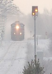 A Finnish distant signal at the western approach to Muhos station is displaying Expect Stop. In the background, express train 81 is pulling away from the station.
It is important to understand that for signals that use colored aspects, the color of each individual light is subsumed in the overall pattern. In the United States, for example, it is common to see a "Clear" aspect consisting of a green light above a red light. The red light in this instance does not indicate "Stop"; it is simply a component of a larger aspect. Operating rules normally specify that when there is some imperfection in the display of an aspect (e.g., an extinguished lamp), the indication should be read as the most restrictive indication consistent with what is displayed.
Signals control motion past the point at which the signal stands and into the next section of track. They may also convey information about the state of the next signal to be encountered. Signals are sometimes said to "protect" the points/switches, section of track, etc. that they are ahead of. The term "ahead of" can be confusing, so official UK practice is to use the terms in rear of and in advance of. When a train is waiting at a signal it is "in rear of" that signal and the danger being protected by the signal is "in advance of" the train and signal.
A distinction must be made between absolute signals, which can display a "Stop" (or "Stop and Stay") indication, and permissive signals, which display a "Stop & Proceed" aspect. Furthermore, a permissive signal may be marked as a Grade Signal where a train does not need to physically stop for a "Stop & Proceed" signal, but only decelerate to a speed slow enough to stop short of any obstructions. Interlocking ('controlled') signals are typically absolute, while automatic signals (i.e. those controlled through track occupancy alone, not by a signalman) are usually permissive.[verification needed]
Drivers need to be aware of which signals are automatic. In current British practice for example, automatic signals have a white rectangular plate with a black horizontal line across it. In US practice a permissive signal typically is indicated by the presence of a number plate. Some types of signal display separate permissive and absolute stop aspects.
Approach lighting leaves the signal dark (or dimmed) when a train is not present. This may be applied for sighting reasons, or simply to extend the life of the lamp and save the batteries. The first such application was on the Atchison, Topeka and Santa Fe Railway on their two arm, lower quadrant Union Switch & Signal (US&S) Style "B" semaphores at the turn of the 19th to the 20th century.[citation needed]
Operating rules generally dictate that a dark signal must be interpreted as displaying its most restrictive aspect (generally "Stop" or "Stop and Proceed").
Signal forms
Signals differ both in the manner in which they display aspects and in the manner in which they are mounted with respect to the track.
Mechanical signals
Main article: Railway semaphore signal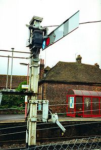 A British semaphore signal on the former Southern Region of British Railways
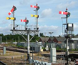
The oldest forms of signal displayed their different indications by a part of the signal being physically moved. The earliest types comprised a board that was either turned face-on and fully visible to the driver, or rotated away so as to be practically invisible. These signals had two or at most three positions.
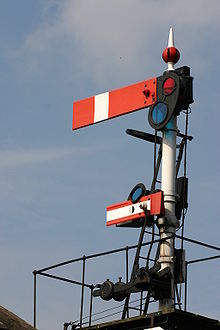
Semaphore signals were patented in the early 1840s by Joseph James Stevens, and soon became the most widely-used form of mechanical signal, although they are now decreasing in number. The semaphore arm consists of two parts: An arm or blade which pivots at different angles, and a spectacle holding coloured lenses which move in front of a lamp in order to provide indications at night. Usually these were combined into a single frame, though in some types (e.g. "somersault" signals in which the arm pivoted in the centre), the arm was separate from the spectacle. The arm projects horizontally in its most restrictive aspect; other angles indicate less restrictive aspects.
Semaphores come in "lower quadrant" and "upper quadrant" forms. In lower quadrant signals, the arm pivots down for less restrictive aspects. Upper quadrant signals, as the name implies, pivot the arm upward. Either type may be capable of showing two or three indications depending on the application. For example, it was common in the United States for train order signals to point the arm straight down to indicate "Proceed."
The colour and shape of the arm is commonly varied to show the type of signal and therefore type of indication displayed. A common pattern was to use red, square-ended arms for "stop" signals and yellow "fishtail" arms for "distant" signals. A third type with a pointed end extending outward (in the opposite direction from the fishtail shape) may indicate "proceed at restricted speed after stopping" (and indeed, stopping itself is often waived for heavy freight ("tonnage") trains already moving at slow speed).
The first railway semaphore was erected by Charles Hutton Gregory on the London and Croydon Railway (later the Brighton) at New Cross, southeast London, in the winter of 1842-1843 on the newly enlarged layout also accommodating the South Eastern Railway. The semaphore was afterwards rapidly adopted as a fixed signal throughout Britain, superseding all other types in most uses by 1870. Such signals were widely adopted in the U.S. after 1908.
Initially, railway semaphores were mounted on the roof of the controlling signal box, but gradually a system of wires and pulleys controlled through mechanical linkages was developed to control the signals at a distance. Signal boxes became controllers of interlockings, and came to be known as interlocking towers or simply signal towers in the United States, while retaining the name "signal box" in the United Kingdom. The signals protecting the station itself came to be called home signals, while signals some distance away giving advance warning came to be called distant signals.
Mechanical signals may be operated by electric motors or hydraulically. The signals are designed to be fail-safe so that if power is lost or a linkage is broken, the arm will move by gravity into the horizontal position. For lower quadrant semaphores, the positioning of the spectacles and their housing on the opposite side of the pivot to the arm will force the signal to return to danger - the arm itself is relatively light compared to these.
In the U.S., semaphores were employed as train order signals,[1] with the purpose of indicating to engineers whether they should stop to receive a telegraphed order, and also as simply one form of block signalling. Mechanical signals worldwide are being phased out in favour of colour-light signals or, in some cases, signalling systems that do not require lineside signals (e.g. Radio Electronic Token Block or RETB).
Colour light signals
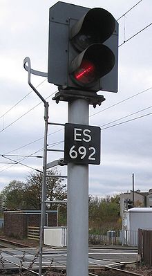 Network Rail (UK) two-aspect colour light railway signal set at 'danger'
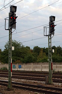 German railway signals showing aspect Hp0 (Stop)
The introduction of electric light bulbs made it possible to produce colour light signals which were bright enough to be seen during daylight, starting in 1904. These at first were "short range" signals, used in low speed applications. Improvements in signal glassware by Dr. Churchill of Cornell University in conjunction with Corning Glass Works (Corning, New York) increased the daylight viewing range to that of "medium range" signals. These were quickly adopted by many U.S. rapid transit and trolley (street, light) railway systems. Ultimately, by 1913, Dr. Churchill developed the "doublet lens" combination wherein an outer clear Fresnel lens was sealed with inwards facing ribs to an inner glass of the desired color with ribs facing the outer lens. Both inner and outer exposed surfaces were therefore smooth, avoiding dirt accumulation. The inner lens convexity permitted a 35 watt, 10 volt lamp filament to be almost surrounded by this system, gathering much more of the light produced than with previous systems. This yielded the first true "Long Range" daylight signal with a range of over 2,500 feet (760 m) under bright sun conditions. The first application was by the Chicago, Milwaukee, St. Paul and Pacific Railroad's use of the US&S "Style L" colour light signal on their line through the Pacific Northwest in 1914. These were intentionally fitted from the start with two lamps one ahead of the other, the circuitry so arranged that failure of the main lamp caused the lighting the back-up lamp to assure the most restrictive indication always being illuminated. The final improvement came in the early 1920s with Corning's "High Transmission" glass colours increasing this range to 3,500 feet (1,100 m) under bright sun conditions. The results were that in the U.S., all semaphore manufacturing had ceased by 1944, having been completely replaced with light signals of one type or another.
The signal head is the portion of a colour light signal which displays the aspects. To display a larger number of indications, a single signal might have multiple signal heads. Some systems used a single head coupled with auxiliary lights to modify the basic aspect.
Colour light signals come in two forms; both were developed in the first quarter of the 20th century in the U.S. The most prevalent form is the multi-unit type, with separate lights and lenses for each colour, in the manner of a traffic light. Hoods and shields are generally provided to shade the lights from sunlight which could cause false indications; coloured Fresnel lenses are used to focus the beam, though reflectors are often not used, to prevent false indications from reflected sunlight. The lights may be mounted vertically or in a triangle; usually green is on top and red at the bottom. Signals with more than three aspects to display generally have multiple heads to display combinations of colours.
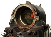
Mechanism of a searchlight signal made by Union Switch & Signal, with the lamp and reflector removed to expose the coloured roundels
Searchlight signals were the most often used signal type in the U.S.[citation needed] until recently, although these have become less popular due to vandalism. In these, a single incandescent light bulb is used in each head, and either an A.C. or D.C. relay mechanism is used to move a coloured spectacle (or "roundel") in front of the lamp. In this manner, gravity (fail safe) returns the red roundel into the lamp's optical path. In effect, this mechanism is very similar to the colour light signal that is included in an electrically operated semaphore signal, except that the omission of the semaphore arm allows the roundels to be miniaturized and enclosed in a weatherproof housing. An elliptical reflector focuses the lamp through the roundel a small lens and then a larger single or compound lensing arrangement is employed.[2] The Hall Signal Company first produced this type of signal in 1920, having purchased the patent rights from one Mr. Blake in 1918. US&S bought the Hall Company in 1925 thus naming this signal the Style "H," with the later compound lens version (introduced in 1932) referred to as the Style "H-2." The General Railway Signal Company's versions were known as the "Type S, SA, SA-1 and SC", the last having a sequential operating mechanism that could be used to directly replace motor-operated semaphores without any changes in system wiring.
The viewing angle for the searchlight beam, though narrow, is enormously powerful. Initial range was in excess of one mile and that was in 1918. Deflecting cover glasses are used to give a spread of the indication on non tangent track as needed. Again, to display more than three aspects, multiple heads are used as is standard U.S. practice, that of A.H. Rudd's 1915 "Speed Signalling System." Searchlight signals have the disadvantage of having moving parts which may be deliberately tampered with. From World War II onward, they were widely used in the U.S. for new work until the last fifteen to twenty years when vandalism began to render them vulnerable to false indications.
A variant of the above, a "medium range" single lens signal, is the "Unilens" signal made by Safetran Systems Corporation. This uses a single-lens system, fed by three or four individual halogen lamps with parabolic reflectors behind them. These lamps shine through the same coloured roundels used in searchlight signals into individual fibre-optic elements, which are rolled together as sheets to make a solid cable as it were at the focal point of the lens assembly. This makes it possible to show four different colours (usually red/yellow/green/lunar white) from a single signal head, which is not possible for the traditional searchlight mechanism, nor is it necessary. The marginal medium range aspect of this signal is often somewhat compensated by the use of the illumination of two red lamps simultaneously lit to improve visual range. Current consumption of this arrangement would have been prohibitive during the 20th century, when most signals were battery powered.
More recently, clusters of LEDs have started to be used in place of the incandescent lamps, reflectors and lenses. These use less power and have a purported working life of ten years, but this may not in reality be the case. These are often arranged so that the same aperture is used for whichever colour light is required, but again only for medium or short range use as the number per colour of discrete LEDs is much less than found on high signals intended for long range application.
Operating rules generally dictate that a dark signal be interpreted as giving the most restrictive indication it can display (generally "stop" or "stop and proceed"). Obviously this greatly impedes traffic until repairs are made. Therefore many colour light systems have circuitry to detect failures in lamps or mechanism, allowing the signal to compensate for the failure by displaying an aspect which, while more restrictive than that set by the dispatcher or signalling equipment, still allows traffic to pass; for example, if a green lamp is burned out, but the indication to be displayed is "clear", the signal can detect this and display a cautionary aspect using a different lamp or lamps, allowing traffic to proceed at reduced speeds without stopping.
In the UK, most filament-type colour light signals are equipped with lamps having two filaments. When the main filament fails, the auxiliary filament automatically comes into use. Failure of the main filament is indicated to the technician (but not the signalman), who will then arrange for the lamp to be replaced. Failure of both filaments, resulting in a 'dark' signal, is indicated to the signalman, inside the signal box; also, the previous signal may also be restricted to no more than a yellow warning aspect.
Position light signals
A position light signal is one where the position of the lights, rather than their colour, determines the meaning. The aspect consists solely of a pattern of illuminated lights, which are all of the same colour (typically amber or white). In many countries, small position light signals are used as shunting signals, while the main signals are of colour light form. Also, many tramway systems (such as the Metro of Wolverhampton) use position light signals.
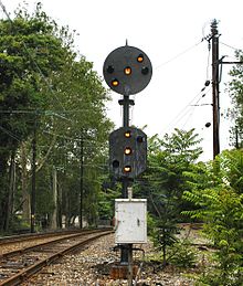
On the Pennsylvania Railroad (PRR) as on other railroads, initial efforts were made to replace the semaphore with illumination of the position of the blade rather than by colour lamps alone. This had the advantage of eliminating any and all effects of even slight colour blindness by the train crew. Lamps with inverted half toric optic lenses, covered with a light yellow tinted conical cover glass with a frosted tip to avoid phantom indications were displayed in rows of three, corresponding to the positions of a semaphore blade. Multiple signal heads were used at interlockings where four aspects did not suffice. The PRR chose to use their Superintendent of Signaling, A.H.Rudd's, in-house developed position light signals to both replace the semaphores and their moving parts, also because the intense lemon yellow light provided superior visibility in adverse weather conditions such as rain or fog. The prototype position lights used rows of four lamps in an asymmetric fashion in the style of semaphore blades, but this was later changed to the symmetric three-lamp system. The first installation of the four 5 volt, 10 watt lamp position light signals occurred on the Main Line between Philadelphia and Paoli, in conjunction with the 1915 electrification. These first signals differed from the later ones in that the lamps were mounted separately in front of a tombstone-shaped black painted metal backing. There were found issues with wind damage due to the rather larger "sail area" of the "tombstone backing." Soon thereafter, the lamps were reduced in number to three per row, without adversely affecting the long range viewing of the signal aspects and the backing correspondingly reduced in size and made as a disc. The lamp units and background disc on a mounting system known as a "spider," were integrated into a single unit.
 Two-head colour position signal on CSXT mainline near Magnolia, West Virginia. The left head displays "Stop"; the right head, "Clear".
Colour-position signals
A system combining aspects of the colour and position systems was developed on the Baltimore and Ohio Railroad (B&O) in 1920 and was patented by L.F. Loree and F.P. Patenall. In effect, it is a "digital" semaphore. It was also applied to the Chicago and Alton Railroad when the latter was under B&O control. The color position lights (CPLs) were first installed as a pilot on the Staten Island Railway in New York City, a former B&O subsidiary, later turned rapid transit line operated by the Metropolitan Transportation Authority. The B&O system used a central round head with pairs of lights mimicking the speed signalling system of semaphore positions developed by A.H. Rudd and accepted as standard by the American Railway Association Signal Section in 1915. It used pairs of large coloured lights (green |, yellow /, red --). with a lunar white \ also being present in some installations.
Signal mounting
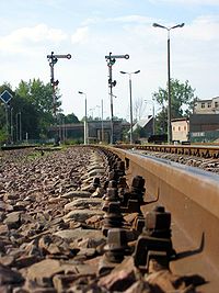
Lineside signals need to be mounted in proximity to the track which they control.
Post mounting
When a single track is involved, the signal is normally mounted on a post which displays the arm or signal head at some height above the track, in order to allow it to be seen at a distance. The signal is normally put on the engine driver's side of the track.
Gantry mounting
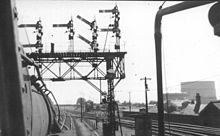
When multiple tracks are involved, or where space does not permit post mounting, other forms are found. In double track territory one may find two signals mounted side by side on a bracket which itself is mounted on a post. The left hand signal then controls the left-hand track, and the right signal the right-hand track. A gantry or signal bridge may also be used. This consists of a platform extending over the tracks; the signals are mounted on this platform over the tracks they control.
Ground mounting
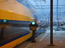 Dwarf signal at Utrecht Centraal, Netherlands
In some situations where there is insufficient room for a post or gantry, signals may be mounted at ground level. Such signals may be physically smaller (termed dwarf signals). Rapid transit systems commonly use nothing but dwarf signals due to the restricted space. In many systems, dwarf signals are only used to display 'restrictive' aspects such as low speed or shunt aspects, and do not normally indicate 'running' aspects.
Other
Occasionally, a signal may be mounted to a structure such as a retaining wall, bridge abutment, or overhead electrification support.
Filaments
Electric lamps for railway signals are often fitted with twin filaments, so that if one burns out, the other keeps the signal lit. A more complicated version of this, such as in the SL35 lamp, a filament changeover relay is fitted in series with the first filament, where if the first filament burns out, the relay drops and lights the second filament. This filament fail relay also activates an alarm in the signal box.
Lamp proving
When lamps fail, this can result in aspects that are less restrictive (high speed) that when the lamps are correctly lit. This is potentially dangerous.
For example, in UK practice, if a white "feather" indicator fails, the low speed feather combined with a green light, which is low speed, becomes a green light on its own, which is high speed. A lamp proving relay would detect the failed feather indicator, and prevent the green from showing. It can also display an indication on the signaller's panel.
Control and operation of signals
Signals were originally controlled by levers situated at the signals, and later by levers grouped together and connected to the signal by wire cables, or pipes supported on rollers (US). Often these levers were placed in a special building, known as a signal box (UK) or interlocking tower (US), and eventually they were mechanically interlocked to prevent the display of a signal contrary to the alignment of the switch points. Automatic traffic control systems added track circuits to detect the presence of trains and alter signal aspects to reflect their presence or absence.
Cab signalling
Main article: Cab signallingSome locomotives are equipped to display cab signals. These can display signal indications through patterns of lights in the locomotive cab, or in simple systems merely produce an audible sound to warn the driver of a restrictive aspect. Occasionally, cab signals are used by themselves, but more commonly they are used to supplement signals placed at lineside. Cab signalling is particularly useful on high speed railways. In the absence of lineside signals, fixed markers may be provided at those places where signals would otherwise exist, to mark the limit of a movement authority.
Signalling power
Usually, signals and other equipment (such as track circuits and level crossing equipment), are powered from a low voltage supply. The specific voltage varies with the country and equipment used. The reason behind this is that the low voltage allows easy operation from storage batteries and indeed, in some parts of the world (and previously in many more locations, before the widespread adoption of electricity), batteries are the primary power source, as mains power may be unavailable at that location. In urban built-up areas, the trend is now to power signal equipment directly from mains power, with batteries only as backup.
See also
References
- Armstrong, John (1957). "All About Signals" (Two-article series). Trains Magazine, June and July 1957.
- Calvert, J.B. "The Origin of the Railway Semaphore." 2007-05-04.
- Kichenside, G. and Williams, A., (1998), Two Centuries of Railway Signalling, Oxford Publishing Co., ISBN 0-86093-541-8
- Vanns, M.A., (1995), Signalling in the Age of Steam, Ian Allan, ISBN 0-7110-2350-6
Notes
- ^ Calvert, J.B. "Train Order Signals." Railways: History, Signalling, Engineering. 2004-08-10.
- ^ Railway Signal Site. "US&S Searchlight Signal H and H2 Styles." Accessed 2011-09-11.
External links
- Signal Page - world wide railway signalling info and references
Railway signalling Block systems Signalling control Signals Train detection Train protection Automatic Train Control • Automatic Train Protection • Automatic Warning System • Automatische treinbeïnvloeding • Balise • Catch points • Chinese Train Control System • Continuous Automatic Warning System • Contrôle de vitesse par balises • EBICAB • Integra-Signum • Interoperable Communications Based Signaling • Le Crocodile • Linienzugbeeinflussung • Pulse code cab signaling • Punktförmige Zugbeeinflussung • RS4 Codici • Sistema Controllo Marcia Treno • Slide fence • Train Automatic Stopping Controller • Train Protection & Warning System • Train stop • Transmission Voie-Machine • Level crossingOrganisations By country Australia • Belgium • Canada • Finland • France • Germany • Greece • Italy • Japan • Netherlands • North America • Norway • Sweden • Switzerland • United KingdomRailway infrastructure Permanent way Permanent way (history) • Permanent way (current) • Railroad tie/Sleeper • Rail fastening system • Track ballast • Rail profile • Fishplate • Breather switch • Datenail • Axe ties • Ladder track • Baulk road • Cant • Minimum radius • Track transition curveTrackwork and track structures Junction • Wye • Railroad switch • Gauntlet track • Railway electrification system • Overhead lines • Track gauge • Railway turntable • Water crane • Track pan • Rail track • Tramway track • Classification yard • Rail yard • Siding • Passing loop • Balloon loopSignalling and safety Railway signalling • Signalling control • Railway signal • Interlocking • Level crossing • Buffer stop • Catch points • Loading gauge • Structure gauge • Block postBuildings Categories:- Rail infrastructure
- Railway signalling
Wikimedia Foundation. 2010.

