- Otto cycle
-
See also: Otto engine and Four-stroke engine
An Otto cycle is an idealized thermodynamic cycle which describes the functioning of a typical reciprocating piston engine, the thermodynamic cycle most commonly found in automobile engines.[1]
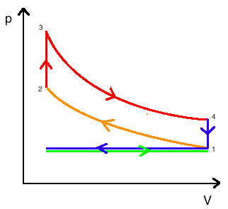
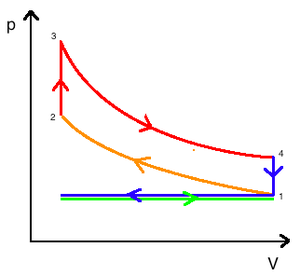 Pressure-Volume diagram
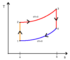 Temperature-Entropy diagram
The idealized diagrams of a four-stroke Otto cycle Both diagrams:
the intake (A) stroke is performed by an isobaric expansion, followed by an adiabatic compression (B) stroke. Through the combustion of fuel, heat is added in an isochoric process, followed by an adiabatic expansion process, characterizing the power (C) stroke. The cycle is closed by the exhaust (D) stroke, characterized by isochoric cooling and isobaric compression processes.The Otto cycle is constructed out of:
- TOP and BOTTOM of the loop: a pair of quasi-parallel adiabatic processes
- LEFT and RIGHT sides of the loop: a pair of parallel isochoric processes
The adiabatic processes are impermeable to heat: heat flows into the loop through the left pressurizing process and some of it flows back out through the right depressurizing process, and the heat which remains does the work.
The processes are described by [2]:
- Process 1-2 is an isentropic compression of the air as the piston moves from bottom dead center to top dead center.
- Process 2-3 is a constant-volume heat transfer to the air from an external source while the piston is at top dead center. This process is intended to represent the ignition of the fuel-air mixture and the subsequent rapid burning.
- Process 3-4 is an isentropic expansion (power stroke).
- Process 4-1 completes the cycle by a constant-volume process in which heat is rejected from the air while the piston is a bottom dead center.
The Otto cycle consists of adiabatic compression, heat addition at constant volume, adiabatic expansion, and rejection of heat at constant volume. In the case of a four-stroke Otto cycle, technically there are two additional processes: one for the exhaust of waste heat and combustion products (by isobaric compression), and one for the intake of cool oxygen-rich air (by isobaric expansion); however, these are often omitted in a simplified analysis. Even though these two processes are critical to the functioning of a real engine, wherein the details of heat transfer and combustion chemistry are relevant, for the simplified analysis of the thermodynamic cycle, it is simpler and more convenient to assume that all of the waste-heat is removed during a single volume change.
A P-V animation of the Otto cycle is very useful in the analysis of the entire process.[3]
Contents
History
The four-stroke engine was first patented by Alphonse Beau de Rochas in 1861. Before, in about 1854–57, two Italians (Eugenio Barsanti and Felice Matteucci) invented an engine that was rumored to be very similar, but the patent was lost.
"The request bears the no. 700 of Volume VII of the Patent Office of the Reign of Piedmont. We do not have the text of the patent request, only a photo of the table which contains a drawing of the engine. We do not even know if it was a new patent or an extension of the patent granted three days earlier, on December 30, 1857, at Turin."
f. Eugenio Barsanti and Felice Matteucci, June 4, 1853 [4]The first person to build a working four stroke engine, a stationary engine using a coal gas-air mixture for fuel (a gas engine), was German engineer Nicolaus Otto.[5] This is why the four-stroke principle today is commonly known as the Otto cycle and four-stroke engines using spark plugs often are called Otto engines.
Processes
Process 1-2 (B on diagrams)
Piston moves from crank end (bottom dead center BDC) to cover end (top dead center TDC) and an ideal gas with initial state 1 is compressed isentropically to state point 2, through compression ratio (V1 / V2). Mechanically this is the adiabatic compression of the air/fuel mixture in the cylinder, also known as the compression stroke. Generally the compression ratio is around 9-10:1 (V1:V2) for a typical engine.[6]
Process 2-3 (C on diagrams)
The piston is momentarily at rest at TDC and heat is added to the working fluid at constant volume from an external heat source which is brought into contact with the cylinder head. The pressure rises and the ratio (P3 / P4) is called the "explosion ratio". At this instant the air/fuel mixture is compressed at the top of the compression stroke with the volume essentially held constant, also known as ignition phase.
Process 3-4 (D on diagrams)
The increased high pressure exerts a greater amount of force on the piston and pushes it towards the BDC. Expansion of working fluid takes place isentropically and work is done by the system. The volume ratio (V4 / V3) is called "isentropic expansion ratio". Mechanically this is the adiabatic expansion of the hot gaseous mixture in the cylinder head, also known as expansion (power) stroke.
Process 4-1 (A on diagrams)
The piston is momentarily at rest at BDC and heat is rejected to the external sink by bringing it in contact with the cylinder head. The process is so controlled that ultimately the working fluid comes to its initial state 1 and the cycle is completed. Many petrol and gas engines work on a cycle which is a slight modification of Otto cycle. This cycle is called "constant volume cycle" because the heat is supplied to air at constant volume.
Exhaust and intake strokes
Exhaust stroke-ejection of the gaseous mixture via an exhaust valve through the cylinder head. Induction stroke-intake of the next air charge into the cylinder. The volume of the exhaust gasses is the same as the air charge.[6]
Cycle Analysis
Processes 1-2 and 3-4 do work on the system but no heat transfer occurs during adiabatic expansion and compression. Processes 2-3 and 4-1 are isochoric therefore heat transfer occurs but no work is done. No work is done during a isochoric (constant volume) because work requires movement; when the piston volume does not change no shaft work is produced by the system. Four different equations can be derived by neglecting kinetic and potential energy and considering the first law of thermodynamics (energy conservation). Assuming these conditions the first law is rewritten as:[2]
- ΔE = ΔU = Qin − Wout
Applying this to the Otto cycle the four process equations can be derived:
Since the first law is expressed as heat added to the system and work expelled from the system then (W1 − 2 / m) and (Q4 − 1 / m) will always produce positive values. However, since work always involves movement, processes 2-3 and 4-1 will be omitted because they occur at a constant volume. The net work can be expressed as:
The net work can also be found by evaluating the heat added minus the heat leaving or expelled.
Thermal efficiency is the quotient of the net work to the heat addition into system. Upon rearrangement the thermal efficiency can be obtained (Net Work/Heat added):
Equation 1:
Alternatively, thermal efficiency can be derived by strictly heat added and heat rejected.
In the Otto cycle, there is no heat transfer during the process 1-2 and 3-4 as they are reversible adiabatic processes. Heat is supplied only during the constant volume processes 2-3 and heat is rejected only during the constant volume processes 4-1.[7]
Equation 1 can now be related to the specific heat equation for constant volume. The specific heats are particularly useful for thermodynamic calculations involving the ideal gas model.
Rearranging yields:
- u = (cv)(δT)
Inserting the specific heat equation into the thermal efficiency equation (Equation 1) yields.
Upon rearrangement:
Next, noting from the diagrams T4 / T1 = T3 / T2, thus both of these can be omitted. The equation then reduces to:
Equation 2:
Since the Otto cycle is an isentropic process the isentropic equations of ideal gases and the constant pressure/volume relations can be used to yield Equations 3 & 4.
Equation 3:
Equation 4:
-
-
-
- The derivation of the previous equations are found by solving these four equations respectively (where R is the gas constant):
-
-
Further simplifying Equation 4, where r is the compression ratio (V1 / V2):
Equation 5:
Also, note that
where γ is the specific heat ratio
From inverting Equation 4 and inserting it into Equation 2 the final thermal efficiency can be expressed as [7]:
Equation 6:
From analyzing equation 6 it is evident that the Otto cycle depends directly upon the compression ratio r. Since the γ for air is 1.4, an increase in r will produce an increase in η. However, the γ for the combustion products of the fuel/air mixture is taken at approximately 1.3. The foregoing discussion implies that it is more efficient to have a high compression ratio. The standard ratio is approximately 10:1 for typical automobiles. Usually this does not increase much because of the possibility of autoignition, or "knock", which places an upper limit on the compression ratio.[2] During the compression process 1-2 the temperature rises, therefore an increase in the compression ratio causes an increase in temperature. Autoignition occurs when the temperature of the fuel/air mixture becomes too high before it is ignited by the flame front. The compression stroke is intended to compress the products before the flame ignites the mixture. Therefore if the compression ratio was increased, the mixture could be compressed before ignition leading to "engine knocking". This can damage engine components and will decrease the original horsepower of the engine.
References
- ^ Wu, Chih. Thermodynamic Cycles: Computer-aided Design and Optimization. New York: M. Dekker, 2004. Print.
- ^ a b c Moran, Michael J., and Howard N. Shapiro. Fundamentals of Engineering Thermodynamics. 6th ed. Hoboken, N.J. : Chichester: Wiley ; John Wiley, 2008. Print.
- ^ "Animated Diagram". Leipzig. 2006. http://techni.tachemie.uni-leipzig.de/otto/index_e.html. Retrieved 2010-09-22.
- ^ "Documenti Storici". Barsantiematteucci.it. http://www.barsantiematteucci.it/inglese/documentiStorici.html. Retrieved 2010-09-22.
- ^ Gunston, Bill (1999). Development of Piston Aero Engines (2 ed.). Sparkford, UK: Patrick Stephens Ltd. p. 21. ISBN 0 7509 4478 1.
- ^ a b "Heat Cycles - Electropeaedia". Woodbank Communications Ltd. http://www.mpoweruk.com/heat_engines.htm. Retrieved 2011-04-11.
- ^ a b Gupta, H. N. Fundamentals of Internal Combustion. New Delhi: Prentice-Hall, 2006. Print.
Categories:- Piston engines
- Thermodynamic cycles


Wikimedia Foundation. 2010.