- Heat exchanger
-
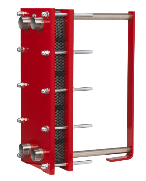
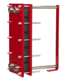 An interchangeable plate heat exchanger
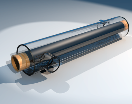
 Tubular heat exchanger.
A heat exchanger is a piece of equipment built for efficient heat transfer from one medium to another. The media may be separated by a solid wall, so that they never mix, or they may be in direct contact.[1] They are widely used in space heating, refrigeration, air conditioning, power plants, chemical plants, petrochemical plants, petroleum refineries, natural gas processing, and sewage treatment. The classic example of a heat exchanger is found in an internal combustion engine in which a circulating fluid known as engine coolant flows through radiator coils and air flows past the coils, which cools the coolant and heats the incoming air.
Contents
Flow arrangement
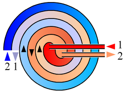
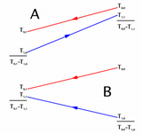 Countercurrent (A) and parallel (B) flows
-
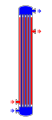
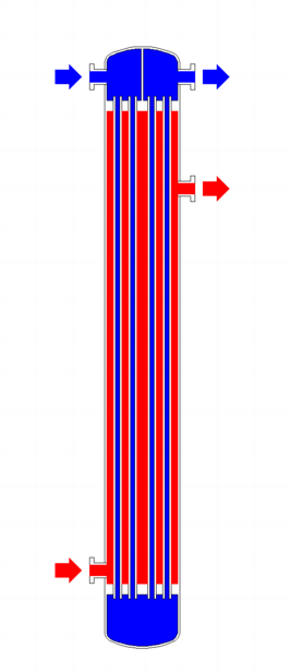
Fig. 1: Shell and tube heat exchanger, single pass (1–1 parallel flow)
-
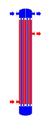
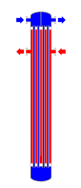
Fig. 2: Shell and tube heat exchanger, 2-pass tube side (1–2 crossflow)
-

Fig. 3: Shell and tube heat exchanger, 2-pass shell side, 2-pass tube side (2-2 countercurrent)
There are two primary classifications of heat exchangers according to their flow arrangement. In parallel-flow heat exchangers, the two fluids enter the exchanger at the same end, and travel in parallel to one another to the other side. In counter-flow heat exchangers the fluids enter the exchanger from opposite ends. The counter current design is most efficient, in that it can transfer the most heat from the heat (transfer) medium. See countercurrent exchange. In a cross-flow heat exchanger, the fluids travel roughly perpendicular to one another through the exchanger.
For efficiency, heat exchangers are designed to maximize the surface area of the wall between the two fluids, while minimizing resistance to fluid flow through the exchanger. The exchanger's performance can also be affected by the addition of fins or corrugations in one or both directions, which increase surface area and may channel fluid flow or induce turbulence.
The driving temperature across the heat transfer surface varies with position, but an appropriate mean temperature can be defined. In most simple systems this is the "log mean temperature difference" (LMTD). Sometimes direct knowledge of the LMTD is not available and the NTU method is used.
Types of heat exchangers
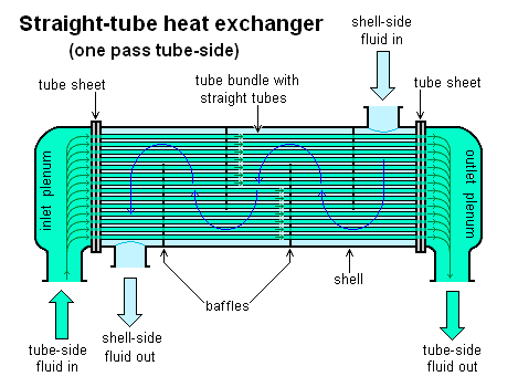
Shell and tube heat exchanger
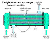 A Shell and Tube heat exchangerMain article: Shell and tube heat exchanger
Shell and tube heat exchangers consist of a series of tubes. One set of these tubes contains the fluid that must be either heated or cooled. The second fluid runs over the tubes that are being heated or cooled so that it can either provide the heat or absorb the heat required. A set of tubes is called the tube bundle and can be made up of several types of tubes: plain, longitudinally finned, etc. Shell and tube heat exchangers are typically used for high-pressure applications (with pressures greater than 30 bar and temperatures greater than 260°C).[2] This is because the shell and tube heat exchangers are robust due to their shape.
There are several thermal design features that are to be taken into account when designing the tubes in the shell and tube heat exchangers. These include:- Tube diameter: Using a small tube diameter makes the heat exchanger both economical and compact. However, it is more likely for the heat exchanger to foul up faster and the small size makes mechanical cleaning of the fouling difficult. To prevail over the fouling and cleaning problems, larger tube diameters can be used. Thus to determine the tube diameter, the available space, cost and the fouling nature of the fluids must be considered.
- Tube thickness: The thickness of the wall of the tubes is usually determined to ensure:
- There is enough room for corrosion
- That flow-induced vibration has resistance
- Axial strength
- Availability of spare parts
- Hoop strength (to withstand internal tube pressure)
- Buckling strength (to withstand overpressure in the shell)
- Tube length: heat exchangers are usually cheaper when they have a smaller shell diameter and a long tube length. Thus, typically there is an aim to make the heat exchanger as long as physically possible whilst not exceeding production capabilities. However, there are many limitations for this, including the space available at the site where it is going to be used and the need to ensure that there are tubes available in lengths that are twice the required length (so that the tubes can be withdrawn and replaced). Also, it has to be remembered that long, thin tubes are difficult to take out and replace.
- Tube pitch: when designing the tubes, it is practical to ensure that the tube pitch (i.e., the centre-centre distance of adjoining tubes) is not less than 1.25 times the tubes' outside diameter. A larger tube pitch leads to a larger overall shell diameter which leads to a more expensive heat exchanger.
- Tube corrugation: this type of tubes, mainly used for the inner tubes, increases the turbulence of the fluids and the effect is very important in the heat transfer giving a better performance.
- Tube Layout: refers to how tubes are positioned within the shell. There are four main types of tube layout, which are, triangular (30°), rotated triangular (60°), square (90°) and rotated square (45°). The triangular patterns are employed to give greater heat transfer as they force the fluid to flow in a more turbulent fashion around the piping. Square patterns are employed where high fouling is experienced and cleaning is more regular.
- Baffle Design: baffles are used in shell and tube heat exchangers to direct fluid across the tube bundle. They run perpendicularly to the shell and hold the bundle, preventing the tubes from sagging over a long length. They can also prevent the tubes from vibrating. The most common type of baffle is the segmental baffle. The semicircular segmental baffles are oriented at 180 degrees to the adjacent baffles forcing the fluid to flow upward and downwards between the tube bundle. Baffle spacing is of large thermodynamic concern when designing shell and tube heat exchangers. Baffles must be spaced with consideration for the conversion of pressure drop and heat transfer. For thermo economic optimization it is suggested that the baffles be spaced no closer than 20% of the shell’s inner diameter. Having baffles spaced too closely causes a greater pressure drop because of flow redirection. Consequently having the baffles spaced too far apart means that there may be cooler spots in the corners between baffles. It is also important to ensure the baffles are spaced close enough that the tubes do not sag. The other main type of baffle is the disc and donut baffle which consists of two concentric baffles, the outer wider baffle looks like a donut, whilst the inner baffle is shaped as a disk. This type of baffle forces the fluid to pass around each side of the disk then through the donut baffle generating a different type of fluid flow.
 Conceptual diagram of a plate and frame heat exchanger.
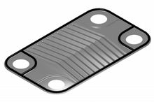 A single plate heat exchanger
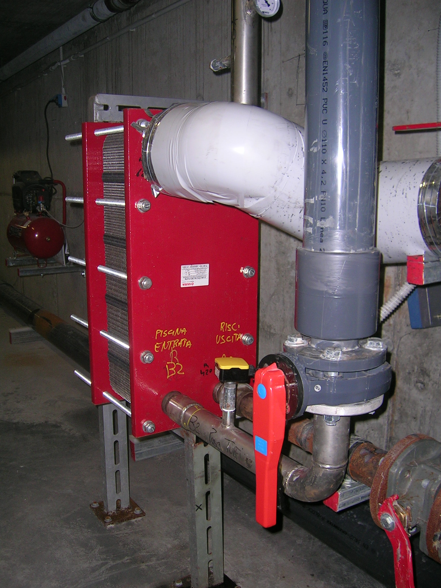
 An interchangeable plate heat exchanger applied to the system of a swimming pool
Plate heat exchanger
Main article: Plate heat exchangerAnother type of heat exchanger is the plate heat exchanger. One is composed of multiple, thin, slightly-separated plates that have very large surface areas and fluid flow passages for heat transfer. This stacked-plate arrangement can be more effective, in a given space, than the shell and tube heat exchanger. Advances in gasket and brazing technology have made the plate-type heat exchanger increasingly practical. In HVAC applications, large heat exchangers of this type are called plate-and-frame; when used in open loops, these heat exchangers are normally of the gasket type to allow periodic disassembly, cleaning, and inspection. There are many types of permanently-bonded plate heat exchangers, such as dip-brazed and vacuum-brazed plate varieties, and they are often specified for closed-loop applications such as refrigeration. Plate heat exchangers also differ in the types of plates that are used, and in the configurations of those plates. Some plates may be stamped with "chevron" or other patterns, where others may have machined fins and/or grooves.
Adiabatic wheel heat exchanger
A third type of heat exchanger uses an intermediate fluid or solid store to hold heat, which is then moved to the other side of the heat exchanger to be released. Two examples of this are adiabatic wheels, which consist of a large wheel with fine threads rotating through the hot and cold fluids, and fluid heat exchangers.
Plate fin heat exchanger
Main article: Plate fin heat exchangerThis type of heat exchanger uses "sandwiched" passages containing fins to increase the effectivity of the unit. The designs include crossflow and counterflow coupled with various fin configurations such as straight fins, offset fins and wavy fins.
Plate and fin heat exchangers are usually made of aluminium alloys which provide higher heat transfer efficiency. The material enables the system to operate at a lower temperature and reduce the weight of the equipment. Plate and fin heat exchangers are mostly used for low temperature services such as natural gas, helium and oxygen liquefaction plants, air separation plants and transport industries such as motor and aircraft engines.
Advantages of plate and fin heat exchangers:
- High heat transfer efficiency especially in gas treatment
- Larger heat transfer area
- Approximately 5 times lighter in weight than that of shell and tube heat exchanger.
- Able to withstand high pressure
Disadvantages of plate and fin heat exchangers:
- Might cause clogging as the pathways are very narrow
- Difficult to clean the pathways
- Aluminum alloys are susceptible to Mercury Liquid Embrittlement Failure
Pillow plate heat exchanger
A pillow plate exchanger is commonly used in the dairy industry for cooling milk in large direct-expansion stainless steel bulk tanks. The pillow plate allows for cooling across nearly the entire surface area of the tank, without gaps that would occur between pipes welded to the exterior of the tank.
The pillow plate is constructed using a thin sheet of metal spot-welded to the surface of another thicker sheet of metal. The thin plate is welded in a regular pattern of dots or with a serpentine pattern of weld lines. After welding the enclosed space is pressurized with sufficient force to cause the thin metal to bulge out around the welds, providing a space for heat exchanger liquids to flow, and creating a characteristic appearance of a swelled pillow formed out of metal.
Fluid heat exchangers
This is a heat exchanger with a gas passing upwards through a shower of fluid (often water), and the fluid is then taken elsewhere before being cooled. This is commonly used for cooling gases whilst also removing certain impurities, thus solving two problems at once. It is widely used in espresso machines as an energy-saving method of cooling super-heated water to be used in the extraction of espresso.
Waste heat recovery units
A Waste Heat Recovery Unit (WHRU) is a heat exchanger that recovers heat from a hot gas stream while transferring it to a working medium, typically water or oils. The hot gas stream can be the exhaust gas from a gas turbine or a diesel engine or a waste gas from industry or refinery.
Dynamic scraped surface heat exchanger
Another type of heat exchanger is called "(dynamic) scraped surface heat exchanger". This is mainly used for heating or cooling with high-viscosity products, crystallization processes, evaporation and high-fouling applications. Long running times are achieved due to the continuous scraping of the surface, thus avoiding fouling and achieving a sustainable heat transfer rate during the process.
The formula used for this will be Q=A*U*LMTD, whereby Q= amount of heat transferred; U= heat transfer coefficient; A=Heat Transfer Area; LMTD = Log mean temperature differential.[3]
Phase-change heat exchangers
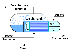 Typical kettle reboiler used for industrial distillation towers
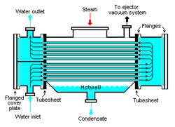 Typical water-cooled surface condenser
In addition to heating up or cooling down fluids in just a single phase, heat exchangers can be used either to heat a liquid to evaporate (or boil) it or used as condensers to cool a vapor and condense it to a liquid. In chemical plants and refineries, reboilers used to heat incoming feed for distillation towers are often heat exchangers.[4][5]
Distillation set-ups typically use condensers to condense distillate vapors back into liquid.
Power plants which have steam-driven turbines commonly use heat exchangers to boil water into steam. Heat exchangers or similar units for producing steam from water are often called boilers or steam generators.
In the nuclear power plants called pressurized water reactors, special large heat exchangers which pass heat from the primary (reactor plant) system to the secondary (steam plant) system, producing steam from water in the process, are called steam generators. All fossil-fueled and nuclear power plants using steam-driven turbines have surface condensers to convert the exhaust steam from the turbines into condensate (water) for re-use.[6][7]
To conserve energy and cooling capacity in chemical and other plants, regenerative heat exchangers can be used to transfer heat from one stream that needs to be cooled to another stream that needs to be heated, such as distillate cooling and reboiler feed pre-heating.
This term can also refer to heat exchangers that contain a material within their structure that has a change of phase. This is usually a solid to liquid phase due to the small volume difference between these states. This change of phase effectively acts as a buffer because it occurs at a constant temperature but still allows for the heat exchanger to accept additional heat. One example where this has been investigated is for use in high power aircraft electronics.
Direct contact heat exchangers
Direct contact heat exchangers involve heat transfer between hot and cold streams of two phases in the absence of a separating wall.[8] Thus such heat exchangers can be classified as:
- Gas – liquid
- Immiscible liquid – liquid
- Solid-liquid or solid – gas
Most direct contact heat exchangers fall under the Gas- Liquid category, where heat is transferred between a gas and liquid in the form of drops, films or sprays. [2]
Such types of heat exchangers are used predominantly in air conditioning, humidification, water cooling and condensing plants.[9]
Phases[10] Continuous phase Driving force Change of phase Examples Gas – Liquid Gas Gravity No Spray columns, packed columns Yes Cooling towers, falling droplet evaporators Forced No Spray coolers/quenchers Liquid flow Yes Spray condensers/evaporation, jet condensers Liquid Gravity No Bubble columns, perforated tray columns Yes Bubble column condensers Forced No Gas spargers Gas flow Yes Direct contact evaporators, submerged combustion HVAC air coils
One of the widest uses of heat exchangers is for air conditioning of buildings and vehicles. This class of heat exchangers is commonly called air coils, or just coils due to their often-serpentine internal tubing. Liquid-to-air, or air-to-liquid HVAC coils are typically of modified crossflow arrangement. In vehicles, heat coils are often called heater cores.
On the liquid side of these heat exchangers, the common fluids are water, a water-glycol solution, steam, or a refrigerant. For heating coils, hot water and steam are the most common, and this heated fluid is supplied by boilers, for example. For cooling coils, chilled water and refrigerant are most common. Chilled water is supplied from a chiller that is potentially located very far away, but refrigerant must come from a nearby condensing unit. When a refrigerant is used, the cooling coil is the evaporator in the vapor-compression refrigeration cycle. HVAC coils that use this direct-expansion of refrigerants are commonly called DX coils.
On the air side of HVAC coils a significant difference exists between those used for heating, and those for cooling. Due to psychrometrics, air that is cooled often has moisture condensing out of it, except with extremely dry air flows. Heating some air increases that airflow's capacity to hold water. So heating coils need not consider moisture condensation on their air-side, but cooling coils must be adequately designed and selected to handle their particular latent (moisture) as well as the sensible (cooling) loads. The water that is removed is called condensate.
For many climates, water or steam HVAC coils can be exposed to freezing conditions. Because water expands upon freezing, these somewhat expensive and difficult to replace thin-walled heat exchangers can easily be damaged or destroyed by just one freeze. As such, freeze protection of coils is a major concern of HVAC designers, installers, and operators.
The introduction of indentations placed within the heat exchange fins controlled condensation, allowing water molecules to remain in the cooled air. This invention allowed for refrigeration without icing of the cooling mechanism.[11]
The heat exchangers in direct-combustion furnaces, typical in many residences, are not 'coils'. They are, instead, gas-to-air heat exchangers that are typically made of stamped steel sheet metal. The combustion products pass on one side of these heat exchangers, and air to be conditioned on the other. A cracked heat exchanger is therefore a dangerous situation requiring immediate attention because combustion products are then likely to enter the building.
Spiral heat exchangers
 Schematic drawing of a spiral heat exchanger.
A spiral heat exchanger (SHE), may refer to a helical (coiled) tube configuration, more generally, the term refers to a pair of flat surfaces that are coiled to form the two channels in a counter-flow arrangement. Each of the two channels has one long curved path. A pair of fluid ports are connected tangentially to the outer arms of the spiral, and axial ports are common, but optional.[12]
The main advantage of the SHE is its highly efficient use of space. This attribute is often leveraged and partially reallocated to gain other improvements in performance, according to well known tradeoffs in heat exchanger design. (A notable tradeoff is capital cost vs operating cost.) A compact SHE may be used to have a smaller footprint and thus lower all-around capital costs, or an over-sized SHE may be used to have less pressure drop, less pumping energy, higher thermal efficiency, and lower energy costs.
Construction
The distance between the sheets in the spiral channels are maintained by using spacer studs that were welded prior to rolling. Once the main spiral pack has been rolled, alternate top and bottom edges are welded and each end closed by a gasketed flat or conical cover bolted to the body. This ensures no mixing of the two fluids will occur. If a leakage happens, it will be from the periphery cover to the atmosphere, or to a passage containing the same fluid.[13]
Self cleaning
SHEs are often used in the heating of fluids which contain solids and thus have a tendency to foul the inside of the heat exchanger. The low pressure drop gives the SHE its ability to handle fouling more easily. The SHE uses a “self cleaning” mechanism, whereby fouled surfaces cause a localized increase in fluid velocity, thus increasing the drag (or fluid friction) on the fouled surface, thus helping to dislodge the blockage and keep the heat exchanger clean. "The internal walls that make up the heat transfer surface are often rather thick, which makes the SHE very robust, and able to last a long time in demanding environments." They are also easily cleaned, opening out like an oven where any build up of foulant can be removed by pressure washing.
Self-Cleaning Water filters are used to keep the system clean and running without the need to shut down or replace cartridges and bags.
Flow Arrangements
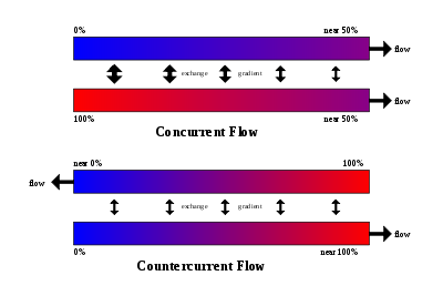 Concurrent and countercurrent flow.
There are three main types of flows in a spiral heat exchanger:
- Counter-current Flow: Fluids flow in opposite directions. These are used for liquid-liquid, condensing and gas cooling applications. Units are usually mounted vertically when condensing vapour and mounted horizontally when handling high concentrations of solids.
- Spiral Flow/Cross Flow: One fluid is in spiral flow and the other in a cross flow. Spiral flow passages are welded at each side for this type of spiral heat exchanger. This type of flow is suitable for handling low density gases which passes through the cross flow, avoiding pressure loss. It can be used for liquid-liquid applications if one liquid has a considerably greater flow rate than the other.
- Distributed Vapour/Spiral flow: This design is a condenser, and is usually mounted vertically. It is designed to cater for the sub-cooling of both condensate and non-condensables. The coolant moves in a spiral and leaves via the top. Hot gases that enter leave as condensate via the bottom outlet.
Applications
The SHE is good for applications such as pasteurization, digester heating, heat recovery, pre-heating (see: recuperator), and effluent cooling. For sludge treatment, SHEs are generally smaller than other types of heat exchangers.[citation needed]
Selection
Due to the many variables involved, selecting optimal heat exchangers is challenging. Hand calculations are possible, but many iterations are typically needed. As such, heat exchangers are most often selected via computer programs, either by system designers, who are typically engineers, or by equipment vendors.
In order to select an appropriate heat exchanger, the system designers (or equipment vendors) would firstly consider the design limitations for each heat exchanger type. Although cost is often the first criterion evaluated, there are several other important selection criteria which include:
- High/ Low pressure limits
- Thermal Performance
- Temperature ranges
- Product Mix (liquid/liquid, particulates or high-solids liquid)
- Pressure Drops across the exchanger
- Fluid flow capacity
- Cleanability, maintenance and repair
- Materials required for construction
- Ability and ease of future expansion
Choosing the right heat exchanger (HX) requires some knowledge of the different heat exchanger types, as well as the environment in which the unit must operate. Typically in the manufacturing industry, several differing types of heat exchangers are used for just the one process or system to derive the final product. For example, a kettle HX for pre-heating, a double pipe HX for the ‘carrier’ fluid and a plate and frame HX for final cooling. With sufficient knowledge of heat exchanger types and operating requirements, an appropriate selection can be made to optimise the process.[14]
Monitoring and maintenance
Online monitoring of commercial heat exchangers is done by tracking the overall heat transfer coefficient. The overall heat transfer coefficient tends to decline over time due to fouling.
U=Q/AΔTlm
By periodically calculating the overall heat transfer coefficient from exchanger flow rates and temperatures, the owner of the heat exchanger can estimate when cleaning the heat exchanger will be economically attractive.
Integrity inspection of plate and tubular heat exchanger can be tested in situ by the conductivity or helium gas methods. These methods confirm the integrity of the plates or tubes to prevent any cross contamination and the condition of the gaskets.
Mechanical integrity monitoring of heat exchanger tubes may be conducted through Nondestructive methods such as eddy current testing.
Fouling
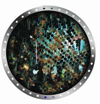
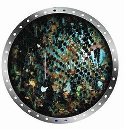 A heat exchanger in a steam power station contaminated with macrofouling.
Fouling occurs when impurities deposit on the heat exchange surface. Deposition of these impurities can be caused by:
- Low wall shear stress
- Low fluid velocities
- High fluid velocities
- Reaction product solid precipitation
- Precipitation of dissolved impurities due to elevated wall temperatures
The rate of heat exchanger fouling is determined by the rate of particle deposition less re-entrainment/suppression. This model was originally proposed in 1959 by Kern and Seaton.
Crude Oil Exchanger Fouling. In commercial crude oil refining, crude oil is heated from 21 °C to 343 °C prior to entering the distillation column. A series of shell and tube heat exchangers is typically used to exchange heat between the crude oil and other oil streams, in order to get the crude to 260 °C prior to heating in a furnace. Fouling occurs on the crude side of these exchangers due to asphaltene insolubility. The nature of asphaltene solubility in crude oil was successfully modeled by Wiehe and Kennedy.[15] The precipitation of insoluble asphaltenes in crude preheat trains has been successfully modeled as a first order reaction by Ebert and Panchal[16] who expanded on the work of Kern and Seaton.
Cooling Water Fouling. Cooling water systems are susceptible to fouling. Cooling water typically has a high total dissolved solids content and suspended colloidal solids. Localized precipitation of dissolved solids occurs at the heat exchange surface due to wall temperatures higher than bulk fluid temperature. Low fluid velocities allow suspended solids to settle on the heat exchange surface. Cooling water is typically on the tube side of a shell and tube exchanger because it's easy to clean. To prevent fouling, designers typically ensure that cooling water velocity is greater than 0.9 m/s and bulk fluid temperature is maintained less than 60 °C. Other approaches to control fouling control combine the “blind” application of biocides and anti-scale chemicals with periodic lab testing.
Maintenance
Plate heat exchangers need to be disassembled and cleaned periodically. Tubular heat exchangers can be cleaned by such methods as acid cleaning, sandblasting, high-pressure water jet, bullet cleaning, or drill rods.
In large-scale cooling water systems for heat exchangers, water treatment such as purification, addition of chemicals, and testing, is used to minimize fouling of the heat exchange equipment. Other water treatment is also used in steam systems for power plants, etc. to minimize fouling and corrosion of the heat exchange and other equipment.
A variety of companies have started using water borne oscillations technology to prevent biofouling. Without the use of chemicals, this type of technology has helped in providing a low-pressure drop in heat exchangers.
In nature
Humans
The human nasal passages serve as a heat exchanger, which warms air being inhaled and cools air being exhaled. You can demonstrate its effectiveness by putting your hand in front of your face and exhaling, first through your nose and then through your mouth. Air exhaled through your nose will be substantially cooler.[17][18]
In species that have external testes (such as humans), the artery to the testis is surrounded by a mesh of veins called the pampiniform plexus. This cools the blood heading to the testis, while reheating the returning blood.
Birds, fish, marine mammals
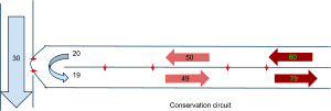 Countercurrent exchange conservation circuit
"Countercurrent" heat exchangers occur naturally in the circulation system of fish, whales and other marine mammals. Arteries to the skin carrying warm blood are intertwined with veins from the skin carrying cold blood, causing the warm arterial blood to exchange heat with the cold venous blood. This reduces the overall heat loss in cold waters. Heat exchangers are also present in the tongue of baleen whales as large volumes of water flow through their mouths.[19][20] Wading birds use a similar system to limit heat losses from their body through their legs into the water.
In industry
Heat exchangers are widely used in industry both for cooling and heating large scale industrial processes. The type and size of heat exchanger used can be tailored to suit a process depending on the type of fluid, its phase, temperature, density, viscosity, pressures, chemical composition and various other thermodynamic properties.
In many industrial processes there is waste of energy or a heat stream that is being exhausted, heat exchangers can be used to recover this heat and put it to use by heating a different stream in the process. This practice saves a lot of money in industry as the heat supplied to other streams from the heat exchangers would otherwise come from an external source which is more expensive and more harmful to the environment.
Heat exchangers are used in many industries, some of which include:
- Waste water treatment
- Refrigeration systems
- Wine-brewery industry
- Petroleum industry.
In the waste water treatment industry, heat exchangers play a vital role in maintaining optimal temperatures within anaerobic digesters so as to promote the growth of microbes which remove pollutants from the waste water. The common types of heat exchangers used in this application are the double pipe heat exchanger as well as the plate and frame heat exchanger.
In aircraft
In commercial aircraft heat exchangers are used to take heat from the engine's oil system to heat cold fuel.[21] This improves fuel efficiency, as well as reduces the possibility of water entrapped in the fuel freezing in components.[22]
Early 2008, a Boeing 777 flying as British Airways Flight 38 crashed just short of the runway. In an early-2009 Boeing-update sent to aircraft operators, the problem was identified as specific to the Rolls-Royce engine oil-fuel flow heat exchangers.[22] Other heat exchangers, or Boeing 777 aircraft powered by GE or Pratt and Whitney engines, were not affected by the problem.[22]
A model of a simple heat exchanger
A simple heat exchanger[23] might be thought of as two straight pipes with fluid flow, which are thermally connected. Let the pipes be of equal length L, carrying fluids with heat capacity Ci (energy per unit mass per unit change in temperature) and let the mass flow rate of the fluids through the pipes be ji (mass per unit time), where the subscript i applies to pipe 1 or pipe 2.
The temperature profiles for the pipes are T1(x) and T2(x) where x is the distance along the pipe. Assume a steady state, so that the temperature profiles are not functions of time. Assume also that the only transfer of heat from a small volume of fluid in one pipe is to the fluid element in the other pipe at the same position. There will be no transfer of heat along a pipe due to temperature differences in that pipe. By Newton's law of cooling the rate of change in energy of a small volume of fluid is proportional to the difference in temperatures between it and the corresponding element in the other pipe:
where ui(x) is the thermal energy per unit length and γ is the thermal connection constant per unit length between the two pipes. This change in internal energy results in a change in the temperature of the fluid element. The time rate of change for the fluid element being carried along by the flow is:
where Ji = Ciji is the "thermal mass flow rate". The differential equations governing the heat exchanger may now be written as:
Note that, since the system is in a steady state, there are no partial derivatives of temperature with respect to time, and since there is no heat transfer along the pipe, there are no second derivatives in x as is found in the heat equation. These two coupled first-order differential equations may be solved to yield:
where k1 = γ / J1, k2 = γ / J2, k = k1 + k2 and A and B are two as yet undetermined constants of integration. Let T10 and T20 be the temperatures at x=0 and let T1L and T2L be the temperatures at the end of the pipe at x=L. Define the average temperatures in each pipe as:
Using the solutions above, these temperatures are:
Choosing any two of the above temperatures will allow the constants of integration to be eliminated, and that will allow the other four temperatures to be found. The total energy transferred is found by integrating the expressions for the time rate of change of internal energy per unit length:
By the conservation of energy, the sum of the two energies is zero. The quantity
 is known as the "log mean temperature difference" and is a measure of the effectiveness of the heat exchanger in transferring heat energy.
See also
- Architectural engineering
- Heat pipe
- Heat pump
- Heat recovery ventilation
- Jacketed vessel
- Log mean temperature difference (LMTD)
- Mechanical engineering
- Micro heat exchanger
- Moving bed heat exchanger
- Packed bed and in particular Packed columns
- Pumpable ice technology
- Reboiler
- Recuperator, or cross plate heat exchanger
- Run around coil
- Steam generator (nuclear power)
- Thermosiphon
- Thermal Wheel, or rotary heat exchanger (including enthalpy wheel and desiccant wheel)
- Waste heat
References
- ^ Sadik Kakaç and Hongtan Liu (2002). Heat Exchangers: Selection, Rating and Thermal Design (2nd ed.). CRC Press. ISBN 0849309026.
- ^ Saunders, E. A. (1988). Heat Exchanges: Selection, Design and Construction. New York: Longman Scientific and Technical.
- ^ Cooling-Coil Heat Transfer: Keystone of System Performance (Trane Engineers Newsletter 31-1). Trane.com. Retrieved on 2011-05-25.
- ^ Kister, Henry Z. (1992). Distillation Design (1st ed.). McGraw-Hill. ISBN 0-07-034909-6.
- ^ Perry, Robert H. and Green, Don W. (1984). Perry's Chemical Engineers' Handbook (6th ed.). McGraw-Hill. ISBN 0-07-049479-7.
- ^ Air Pollution Control Orientation Course from website of the Air Pollution Training Institute
- ^ Energy savings in steam systems Figure 3a, Layout of surface condenser (scroll to page 11 of 34 PDF pages)
- ^ Coulson, J. & Richardson, J. (1983), Chemical Engineering – Design (SI Units), Volume 6, Pergamon Press, Oxford.
- ^ Hewitt G, Shires G, Bott T (1994), Process Heat Transfer, CRC Press Inc, Florida.
- ^ Table: Various Types of Gas – Liquid Direct Contact Heat Exchangers (Hewitt G, Shires G & Bott T, 1994)
- ^ Patent 2,046,968 John C Raisley issued July 7, 1936; filed Jan. 8, 1934 [1]
- ^ Cooling Text[dead link]
- ^ E.A.D.Saunders (1988). Heat Exchangers:Selection Design And Construction Longman Scientific and Technical ISBN 0-582-49491-5
- ^
- White, F.M. ‘Heat and Mass Transfer’ © 1988 Addison-Wesley Publishing Co. pp. 602–604
- Heat Exchangers Kevin D. Rafferty, Gene Culver Geo-Heat Center, 1996–2001 Last Accessed 17/3/08
- For manufacturing engineers who use heat processing equipment- Heat exchanger basics, BNP Media, 2007 Last Accessed 17/3/08
- ^ I. A. Wiehe and R. J. Kennedy, Energy & Fuels, 14, 56 – 63 (2000).
- ^ Panchal C;B; and Ebert W., Analysis of Exxon Crude-Oil-Slip-Stream Coking Data, Proc of Fouling Mitigation of Industrial Heat-Exchanger Equipment, San Luis Obispo, California, USA, p 451, June 1995
- ^ Heat Loss from the Respiratory Tract in Cold, Defense Technical Information Center, April 1955
- ^ Randall, David J.; Warren W. Burggren, Kathleen French, Roger Eckert (2002). Eckert animal physiology: mechanisms and adaptations. Macmillan. p. 587. ISBN 0716738635.
- ^ [2][dead link]
- ^ Heyning and Mead; Mead, JG (November 1997). "Thermoregulation in the Mouths of Feeding Gray Whales". Science 278 (5340): 1138–1140. doi:10.1126/science.278.5340.1138. PMID 9353198. http://www.sciencemag.org/cgi/content/abstract/278/5340/1138. Retrieved 2010-01-19.
- ^ "United States Patent 4498525, Fuel/oil heat exchange system for an engine". United States Patent and Trademark Office. http://www.freepatentsonline.com/4498525.html. Retrieved 3 February 2009.
- ^ a b c "Boeing links Heathrow, Atlanta Trent 895 engine rollbacks". FlightGlobal.com. http://www.flightglobal.com/articles/2009/02/03/322023/boeing-links-heathrow-atlanta-trent-895-engine-rollbacks.html. Retrieved 3 February 2009.
- ^ Kay J M & Nedderman R M (1985) Fluid Mechanics and Transfer Processes, Cambridge University Press
- Coulson, J. and Richardson, J (1999). Chemical Engineering- Fluid Flow. Heat Transfer and Mass Transfer- Volume 1; Reed Educational & Professional Publishing LTD
- Dogan Eryener (2005), ‘Thermoeconomic optimization of baffle spacing for shell and tube heat exchangers’, Energy Conservation and Management, Volume 47, Issue 11–12, Pages 1478–1489.
- G.F.Hewitt, G.L.Shires, T.R.Bott (1994)Process Heat Transfer, CRC Press, Inc, United States Of America.
External links
- Heat Exchangers at the Open Directory Project
- Shell and Tube Heat Exchanger Design Software for Educational Applications (PDF)
- EU Pressure Equipment Guideline
- A Thermal Management Concept For More Electric Aircraft Power System Application (PDF)
- Heat exchanger shellside and tubeside pressure drop calculator Calculate shellside / tubeside pressure drop for an exchanger.
Categories:- Heat exchangers
- Heat transfer
-


Wikimedia Foundation. 2010.