- Rolls-Royce/Snecma Olympus 593
-
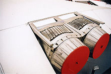
Olympus 593 Preserved Olympus 593 engine at the Imperial War Museum Duxford Type Turbojet National origin United Kingdom/France Manufacturer Rolls-Royce Limited/Snecma First run June 1966 Major applications Concorde Number built 67 Developed from Rolls-Royce Olympus The Rolls-Royce/Snecma Olympus 593 was a reheated (afterburning) turbojet which powered the supersonic airliner Concorde. Initially a joint project between Bristol Siddeley and Snecma based on Bristol's Olympus engine, Rolls-Royce Limited acquired Bristol making it a division of Rolls-Royce.
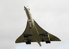
Until Concorde's regular commercial flights ceased the Olympus turbojet was unique in aviation as the only afterburning turbojet powering a commercial aircraft.
Installed in Concorde and while operating at Mach 2, Rolls-Royce engineers claimed that it was the world's most efficient jet engine.[1]
Contents
Development
The Olympus 593 project was started in 1964, using the BAC TSR-2's Olympus 320 as a basis for development. Bristol Siddeley of the UK and Snecma Moteurs of France were to share the project. SNECMA and Bristol were also involved in an unrelated joint project, the M45H turbofan.
Acquiring Bristol Siddeley in 1966, Rolls-Royce continued as the British partner.[2] The early stages validated the basic design concept but many studies were required to achieve desired specifications, e.g.
- The critical factor – fuel consumption
- Pressure Ratio
- Weight/Size
- Turbine entry temperature
Initially, engineers studied using turbojets or turbofans, but the lower frontal cross-sectional area of turbojets in the end was shown to be a critical factor in achieving superior performance. The competing Russian Tu-144 initially used a turbofan, but quickly changed to a turbojet with considerable improvement in performance.[2]
Development of the original Olympus and engine accessories was under Bristol Siddeley, while Snecma was responsible for the variable engine inlet system, the exhaust nozzle/thrust reverser, the afterburner and the noise attenuation system. Britain was to have a larger share in production of the Olympus 593 as France had a larger share in fuselage production.
The Olympus 593B was run in November 1965. The B was a redesign of the 593D which was planned for an earlier smaller Concorde design. Tests of 593D gave further information for the design of the B.[3] The B was dropped later from the designation. SNECMA used an Olympus 301 in testing scaled models of the nozzle system.[4]
In June 1966 a complete Olympus 593 engine and variable geometry exhaust assembly was first run at Melun-Villaroche, Île-de-France, France. At Bristol, flight tests began using a RAF Vulcan bomber with the engine attached to its underside. Due to the Vulcan's aerodynamic limitations the tests were limited to a speed of Mach 0.98 (1,200 km/h). During these tests the 593 achieved 35,190 lbf (157 kN) thrust, which exceeded the requirements of the engine.[5]
In early 1966, the Olympus 593 delivered 37,000 lb of thrust with the use of reheat [6]
In April 1967 the Olympus 593 ran for the first time in a high altitude chamber, at Saclay Île-de-France, France. In January 1968 the Vulcan flying test bed logged 100 flight hours, and the variable geometry exhaust assembly for the Olympus 593 engine was cleared at Melun-Villaroche for flight in the Concorde prototypes.
At 15:40 on the 2nd March 1969 Concorde prototype 001, captained by chief test pilot André Turcat, started its first take off run, with afterburners lit. The four Olympus 593 engines accelerated the aircraft, and after 4,700 feet (1.4 km) of runway and at a speed of 205 knots (380 km/h), captain Turcat lifted the aircraft off for the first time.
67 engines in the end were manufactured.[2]
Plans were drawn up for a quieter and more powerful version of the engine with an extra turbine section and a larger-diameter air compressor that would have eschewed the reheat and added sound-deadening; this would have improved efficiency across the board and permitted rather greater range and opened up new routes, particularly across the Pacific as well as transcontinental across America. However, the poor sales of Concorde meant that this plan for a Concorde 'B' was never put into practice.[7]
Design
A jet engine draws air in at the front and compresses it. The air then combines with fuel and the engine burns the resulting mixture. The combustion greatly increases the volume of the gases which are then exhausted out of the rear of the engine. The Olympus engine took this gas jet and passed it through straightening vanes - to remove swirl. This gas jet then entered the afterburning jet pipe where a ring of fuel injectors sprayed fuel onto the hot exhaust gases. The resulting combustion greatly improved thrust, although it also led to high fuel consumption. The afterburner was thus only used at takeoff and from just below Mach 1 up to Mach 1.7, the engine supercruised above that speed.
The afterburning section was longer than the engine itself (as was the case with all early turbojets) but the thrust of the Olympus 302 rose to 30,610 lbf (136 kN).
Inlet system
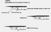
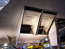
Although not strictly considered part of the engine, the variable engine inlet system was vital to the Olympus 593 on Concorde as supersonic airflow at the engine face could create shock waves that would lead to engine surge and failure. The intake featured variable ramps which altered the intake area which slowed the intake air from supersonic to subsonic speed.[8] This was achieved by positioning the ramps such that shock waves were created at the inlet, air passing through these shock waves was slowed. The inlet air was further decelerated as the intake area increased closer to the engine (speed of air flow decreases as area increases.) During takeoff, when the engine's air demand was high, the ramps were flat at the top and the auxiliary flap was in, allowing more air to enter the engine. As the aircraft approached Mach 0.7, the flap closed; at Mach 1.3, the ramps came into effect, removing air from the engines which was then used in the pressurisation of the cabin. At Mach 2.0, the ramps had covered half their total possible distance. They also helped reduce the work of the compressors by compressing the air and increasing air temperature as a fortunate byproduct of their function.
Any excess air was expelled through doors on the underside of the nacelle and some intake air was bypassed around the engine and mixed with the exhaust - to increase thrust and keep the engine cool. The TSR-2 had used a semicircular design with the shock front adjusted by a translating centrebody to overcome the same problem.[9] In order to achieve the necessary accuracy in the control of the intake ramp and spill positioning, it was found necessary to use a digital signal processor in the Air Intake Control Units. This was developed relatively late in the programme (~1972) but proved successful in ensuring Concorde's fuel economy for transatlantic flights. The digital processor also accomplished the task of accurately calculating the necessary engine spool speed scheduling to ensure an adequate margin in avoiding potentially damaging engine surge under all engine and airframe operating conditions.
The overall pressure ratio of the air by the inlet system as well as the compression within the engine was as high as 80:1 at supersonic speeds.[10] This gave the engine world-beating efficiency.[1]
Compression section
The engine is a twin spool engine with 7 compressor stages on each spool. Unusually, the last 4 compressor stages were made of nickel alloy due to the high pressures and thus high temperatures in supersonic flight- ordinarily, nickel alloy is only used on the turbine sections of jet engines.[11]
Exhaust nozzle
The variable geometry exhaust nozzle consisted of two "eyelids" which varied their position in the exhaust flow dependent on the flight regime, for example when fully closed (into the exhaust flow) they acted as thrust reversers, aiding deceleration from landing to taxi speed.
Variants
- 593 - Original version designed for Concorde
- Thrust : 20,000 lbf (89 kN) dry / 30,610 lbf (136 kN) reheat
- 593-22R - Powerplant fitted to prototypes. Higher performance than original engine due to changes in aircraft specification.
- Thrust : 34,650 lbf (154 kN) dry / 37,180 lbf (165 kN) reheat
- 593-610-14-28 - Final version fitted to production Concorde
- Thrust : 32,000 lbf (142 kN) dry / 38,050 lbf (169 kN) reheat
Specifications (Olympus 593 Mk 610)
General characteristics
- Type: Turbojet
- Length: 4039 mm (159 in)
- Diameter: 1212 mm (47.75 in)
- Dry weight: 3175 kg (7,000 lb)
Components
- Compressor: Axial flow, 7-stage low pressure, 7-stage high pressure
- Combustors: Nickel alloy construction annular chamber, 16 vapourising burners, each with twin outlets
- Turbine: High pressure single stage, low pressure single stage
- Fuel type: Jet A1
Performance
- Maximum thrust: wet: 169.2 kN (38,050 lbf) dry: 139.4 kN (31,350 lbf)
- Overall pressure ratio: 15.5:1
- Specific fuel consumption: 1.195 (cruise), 1.39 (SL) lb/(h·lbf)
- Thrust-to-weight ratio: 5.4:1
See also
- Related development
- Comparable engines
- Related lists
References
- ^ a b NOVA transcript
- ^ a b c [1]
- ^ Flight 6 January 1966
- ^ Flight April 1966
- ^ Testing of Concorde's engine on a Vulcan
- ^ http://www.flightglobal.com/pdfarchive/view/1969/1969%20-%200714.html
- ^ [2]
- ^ Fisher, S.A.; M.C. Neale and A.J. Brooks (1972). "On the sub-critical stability of variable ramp intakes at Mach numbers around 2". Aeronautical Research Council (Her Majesty's Stationery Office). http://naca.central.cranfield.ac.uk/reports/arc/rm/3711.pdf.
- ^ Ausair power Accessed 19 Feb 2007
- ^ [3]
- ^ ConcordeSST:powerplant
- ^ Janes - Online archive, Olympus 593 Retrieved: 9 November 2008
- ^ untitled
External links
- Development of the Olympus 593 a 1969 Flight article on the Olympus 593
- Olympian buckets and spades - a 1971 Flight International article on the Olympus 593s Type 28 TRA secondary nozzle/thrust reverser
Joint development aeroengines Piston engines Turbojets Rolls-Royce plc/Snecma: Olympus 593
Turbofans Allison/Rolls-Royce Limited: TF41
BMW Rolls-Royce: BR700
CFE Company: CFE738
CFM International: CFM56/F108 · LEAP-X
Engine Alliance: GP7000
EuroJet Turbo GmbH: EJ200
GE Honda Aero Engines: HF120
General Electric/Rolls Royce: F136
International Aero Engines: SuperFan · V2500
PowerJet: SaM146
Rolls-Royce/Japanese Aero Engines Corporation: RJ500
Rolls-Royce/MAN Turbo: RB153 · RB193
Rolls-Royce/Snecma: M45H
Rolls-Royce Turbomeca Limited: Adour
Snecma/Turbomeca: Larzac
Turbo-Union: RB199Turboprops/Turboshafts Avco Lycoming/Pratt & Whitney: T800-APW
Europrop International: TP400-D6
HAL/Turbomeca: Ardiden/Shakti
LHTEC: T800
MTU Turbomeca Rolls-Royce: MTR390
Rolls-Royce Turbomeca Limited: RTM322Propfans Pratt & Whitney/Allison: 578-DX
Aeroderivative gas
turbine enginesGeneral Electric/Honeywell: LV100
Lists relating to aviation General Aircraft (manufacturers) · Aircraft engines (manufacturers) · Airlines (defunct) · Airports · Civil authorities · Museums · Registration prefixes · Rotorcraft (manufacturers) · TimelineMilitary Accidents/incidents Records Categories:- Turbojet engines 1960-1969
- France–United Kingdom relations
Wikimedia Foundation. 2010.


