- Delay line memory
-
Computer memory types Volatile - RAM
- In development
- Historical
- Delay line memory
- Selectron tube
- Williams tube
Non-volatile - ROM
- Flash memory
- Early stage
- In development
- Historical
Delay line memory was a form of computer memory used on some of the earliest digital computers. Like many modern forms of electronic computer memory, delay line memory was a refreshable memory, but as opposed to modern random-access memory, delay line memory was serial-access. In the earliest forms of delay line memory, information introduced to the memory in the form of electric pulses was transduced into mechanical waves that propagated relatively slowly through a medium, such as a cylinder filled with a liquid like mercury, a magnetostrictive coil, or a piezoelectric crystal. The propagation medium could support the propagation of hundreds or thousands of pulses at any one time. Upon reaching the other end of the propagation medium, the waves were re-transduced into electric pulses, amplified, shaped, and reintroduced to the propagation medium at the beginning, thus refreshing the memory. Accessing a desired part of the propagation medium's memory contents required waiting for the pulses of interest to reach the end of the medium, a wait typically on the order of microseconds. Use of a delay line for a computer memory was invented by J. Presper Eckert in the mid-1940s for use in computers such as the EDVAC and the UNIVAC I.
Contents
Genesis in radar
The basic concept of the delay line originated with World War II radar research, as a system to reduce clutter from reflections from the ground and other "fixed" objects.
A radar system consists largely of an antenna, a transmitter, a receiver, and a display of some sort. The antenna is connected to the transmitter, which sends out a brief pulse of radio energy before being disconnected again. The antenna is then connected to the receiver, which amplifies any reflected signals, and sends them to the display. Objects farther from the radar return echos later in time than those located closer to the radar, which the display indicates visually.
Non-moving objects at a fixed distance from the antenna always return a signal after the same delay. This would appear as a fixed spot on the display, making detection of other targets in the area more difficult. Early radars simply aimed their beams away from the ground in order to avoid the majority of this "clutter". This was not an ideal situation by any means; it required careful setup and aiming which was not very easy for smaller mobile radars, did nothing to remove other sources of clutter like reflections off certain terrain features, and in the worst case would allow low-flying enemy aircraft to literally fly "under the radar".
To filter these returns out, two pulses were compared, and returns with common timing are removed. To do this, the signal sent from the receiver to the display was split in two, with one path leading directly to the display, and the second leading to a delay unit. The delay was carefully tuned to delay the signals some multiple of the time between pulses (the pulse repetition frequency), that way the delayed signal from an earlier pulse would exit the delay unit at the same time as a newer pulse was being received from the antenna. One of the signals was then inverted, typically the one from the delay, and the two signals were then combined and sent to the display. Any signal that was at the same location was nullified by the inverted signal from a previous pulse, leaving only the moving objects on the display.
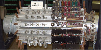
 Mercury memory of UNIVAC I (1951)
Several different types of delay systems were invented for this purpose, with one common principle being that the information was stored acoustically in a medium. MIT experimented with a number of systems including glass, quartz, steel and lead. The Japanese deployed a system consisting of a quartz element with a powdered glass coating that reduced surface waves that interfered with proper reception. The United States Naval Research Laboratory used steel rods wrapped into a helix, but this was useful only for low frequencies under 1 MHz. Raytheon used a magnesium alloy originally developed for making bells.[1]
The first practical de-cluttering system based on the concept was developed by J. Presper Eckert at the University of Pennsylvania's Moore School of Electrical Engineering. His solution used a column of mercury with piezo crystal transducers (a combination of speaker and microphone) at either end. Signals from the radar amplifier were sent to the piezo at one end of the tube, which would cause the transducer to pulse and generate a small wave in the mercury. The wave would quickly travel to the far end of the tube, where it would be read back out by the other piezo, inverted, and sent to the display. Careful mechanical arrangement was needed to ensure the delay time matched the inter-pulse timing of the particular radar being used.
All of these systems were suitable for conversion into a computer memory. The key was to recycle the signals within the memory system so they would not disappear after traveling through the delay. This was relatively easy to arrange with simple electronics.
Acoustic delay lines
Mercury delay lines
After the war Eckert turned his attention to computer development, which was a topic of some interest at the time. One problem with practical development was the lack of a suitable memory device, and Eckert's work on the radar delays meant he had a major advantage over other researchers in this regard.
For a computer application the timing was still critical, but for a different reason. Conventional computers have a natural "cycle time" needed to complete an operation, the start and end of which typically consist of reading or writing memory. Thus the delay lines had to be timed such that the pulses would arrive at the receiver just as the computer was ready to read it. Typically many pulses would be "in flight" through the delay, and the computer would count the pulses by comparing to a master clock to find the particular bit it was looking for.
Mercury was used because the acoustic impedance of mercury is almost exactly the same as that of the piezoelectric quartz crystals; this minimized the energy loss and the echoes when the signal was transmitted from crystal to medium and back again. The high speed of sound in mercury (1450 m/s) meant that the time needed to wait for a pulse to arrive at the receiving end was less than it would have been with a slower medium, such as air, but it also meant that the total number of pulses that could be stored in any reasonably sized column of mercury was limited. Other technical drawbacks of mercury included its weight, its cost, and its toxicity. Moreover, to get the acoustic impedances to match as closely as possible, the mercury had to be kept at a constant temperature. The system heated the mercury to a uniform above-room temperature setting of 40 °C (100 °F), which made servicing the tubes hot and uncomfortable work. (Alan Turing proposed the use of gin as an ultrasonic delay medium, claiming that it had the necessary acoustic properties.[1])
A considerable amount of engineering was needed to maintain a "clean" signal inside the tube. Large transducers were used to generate a very tight "beam" of sound that would not touch the walls of the tube, and care had to be taken to eliminate reflections off the far end of the tubes. The tightness of the beam then required considerable tuning to make sure the two piezos were pointed directly at each other. Since the speed of sound changes with temperature (because of the change in density with temperature) the tubes were heated in large ovens to keep them at a precise temperature. Other systems instead adjusted the computer clock rate according to the ambient temperature to achieve the same effect.
EDSAC, designed to be the first stored-program digital computer, began operation with 512 35-bit words of memory, stored in 32 delay lines holding 576 bits each (a 36th bit was added to every word as a start/stop indicator). In the UNIVAC I this was reduced somewhat, each column stored 120 bits (although the term "bit" was not in popular use at the time), requiring seven large memory units with 18 columns each to make up a 1000-word store. Combined with their support circuitry and amplifiers, the memory subsystem formed its own walk-in room. The average access time was about 222 microseconds, which was considerably faster than the mechanical systems used on earlier computers.
CSIRAC, completed in November 1949, also used delay line memory.
Magnetostrictive delay lines
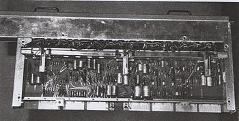
A later version of the delay line used metal wires as the storage medium. Transducers were built by applying the magnetostrictive effect; small pieces of a magnetostrictive material, typically nickel, were attached to either side of the end of the wire, inside an electromagnet. When bits from the computer entered the magnets the nickel would contract or expand (based on the polarity) and twist the end of the wire. The resulting torsional wave would then move down the wire just as the sound wave did down the mercury column. In most cases the entire wire was made of the same material.
Unlike the compressive wave, however, the torsional waves are considerably more resistant to problems caused by mechanical imperfections, so much so that the wires could be wound into a loose coil and pinned to a board. Due to their ability to be coiled, the wire-based systems could be built as "long" as needed, and tended to hold considerably more data per unit; 1k units were typical on a board only 1 foot square. Of course this also meant that the time needed to find a particular bit was somewhat longer as it traveled through the wire, and access times on the order of 500 microseconds were typical.
Delay line memory was far less expensive and far more reliable per bit than flip-flops made from tubes, and yet far faster than a latching relay. It was used right into the late 1960s, notably on British commercial machines like the LEO I, Highgate Wood Telephone Exchange, and various Ferranti machines. Delay line memory was also used for video memory in early terminals, where one delay line would typically store 4 lines of characters. (4 lines x 40 characters per line x 6 bits per character= 960 bits in one delay line) They were also used very successfully in several models of early desktop electronic calculator, including the Friden EC130 (1964) and EC132, the Olivetti Programma 101 desktop programmable calculator introduced in 1965, and the Litton Monroe Epic 2000 and 3000 programmable calculators of 1967.
Piezoelectric delay lines
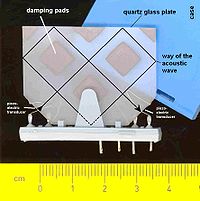
 An ultrasonic delay line from a Colour-TV; it delays the colour signal for 64µs
Manufacturer: VEB ELFEMA Mittweida (GDR) in 1980A similar solution to the magnetostrictive system was to use delay lines made entirely of a piezo material, typically quartz. Current fed into one end of the crystal would generate a compressive wave that would flow to the other end where it could be read out. In effect, piezoelectric delays simply replaced the mercury and transducers of a conventional mercury delay line with a single unit combining both. However these solutions were fairly rare; building crystals of the required quality in large sizes was not easy, limiting them to small sizes, and thus small amounts of data storage.
A better and more widespread use of piezoelectric delays was in European television sets. The European PAL standard for color broadcasts compares the signal from two subsequent lines in order to avoid color shifting due to small phase shifts. By comparing two lines, one inverted, the shifting is averaged out and returns a signal more closely matching the original even under interference. In order to compare the two lines, a piezo delay tuned to the timing of the lines, 64 µs, is inserted in the signal path. The delay unit is shaped to "fold" the beam multiple times through the crystal, greatly reducing its length and producing a small square-ish device.
Electric delay lines
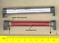
Electric delay lines are used for shorter delay times (ns to several µs). They consist of a long electric line or are made of discrete inductors and capacitors, which are arranged in a chain. To shorten the total length of the line it can be wound around a metal tube, getting some more capacitance against ground and also more inductance due to the wire windings, which are lying close together.
Other examples are:
- short coaxial or microstrip lines for phase matching in high frequency circuits or antennas
- hollow resonator lines in magnetrons and klystrons as helices in travelling wave tubes to match the velocity of the electrons to the velocity of the electromagnetic waves
- undulators in free electron lasers
Another way to create a delay time is to implement a delay line in an integrated circuit storage device. This can be done digitally or with a discrete analogue method. The analogue one uses bucket-brigade devices or charge coupled devices (CCD), which transport a stored electric charge stepwise from one end to the other. Both digital and analog methods are bandwidth limited at the upper end to the half of the clock frequency, which determines the steps of transportation.
In modern computers operating at gigahertz speeds, millimeter differences in the length of conductors in a parallel data bus can cause data-bit skew, which can lead to data corruption or reduced processing performance. This is remedied by making all conductor paths of similar length, delaying the arrival time for what would otherwise be shorter travel distances by using zig-zagging traces.
Optical delay line memory
In the 1980s a team associated with Prof. William Wolf at University of Colorado-Boulder were experimenting with all-optical computers and needed memory that was fast enough to keep up with the optical switches of the processing unit. Their solution was to bounce a laser beam off the corner reflector that had been left on the Moon by the Apollo astronauts, and encode the memory as pulses on the laser beam.[citation needed] With light taking around 2.5 seconds for a round trip to the Moon, and using terahertz pulse rates, the beam had a capacity of several trillion bits. This made it both the longest delay line and the highest capacity memory of any sort available at the time, although of course the apparatus only worked when the Moon was above the horizon.
References
- ^ J.P. Eckert, Jr., A Survey of Digital Computer Memory Systems, Proceedings of the IRE, October 1958
^ Wilkes, Maurice V. (January 1968). "Computers Then and Now". Journal of the ACM (ACM) 15 (1): 1–7. http://portal.acm.org/citation.cfm?id=321440.
External links
- Acoustic Delay Line Memory – has an image of a Ferranti wire-based system about half-way down the page
- Delay line memories – contains a diagram of the magnetostrictive transducer
- Litton Monroe Epic 3000 - Shows details of the torsion delay lines inside this electronic calculator of 1967.
- Magnetostrictive memory, still used in a German computer museum
- U.S. Patent 2,629,827 "Memory System", Eckert-Mauchly Computer Corporation, filed October 1947, patented February 1953
- Display Terminal built with 32 TV delay lines Complete description.
Categories:
Wikimedia Foundation. 2010.


