- Constant k filter
-
Linear analog electronic filters - Constant k filter
- m-derived filter
- General image filters
- Zobel network (constant R) filter
- Lattice filter (all-pass)
- Bridged T delay equaliser (all-pass)
- Composite image filter
- mm'-type filter
Simple filtersedit Constant k filters, also k-type filters, are a type of electronic filter designed using the image method. They are the original and simplest filters produced by this methodology and consist of a ladder network of identical sections of passive components. Historically, they are the first filters that could approach the ideal filter frequency response to within any prescribed limit with the addition of a sufficient number of sections. However, they are rarely considered for a modern design, the principles behind them having been superseded by other methodologies which are more accurate in their prediction of filter response.
Contents
History
Constant k filters were invented by George Campbell. He published his work in 1922,[1] but had clearly invented the filters some time before,[2] as his colleague at AT&T Co, Otto Zobel, was already making improvements to the design at this time. Campbell's filters were far superior to the simpler single element circuits that had been used previously. Campbell called his filters electric wave filters, but this term later came to mean any filter that passes waves of some frequencies but not others. Many new forms of wave filter were subsequently invented; an early (and important) variation was the m-derived filter by Zobel who coined the term constant k for the Campbell filter in order to distinguish them.[3]
The great advantage Campbell's filters had over the RL circuit and other simple filters of the time was that they could be designed for any desired degree of stop band rejection or steepness of transition between pass band and stop band. It was only necessary to add more filter sections until the desired response was obtained.[4]
The filters were designed by Campbell for the purpose of separating multiplexed telephone channels on transmission lines, but their subsequent use has been much more widespread than that. The design techniques used by Campbell have largely been superseded. However, the ladder topology used by Campbell with the constant k is still in use today with implementations of modern filter designs such as the Tchebyscheff filter. Campbell gave constant k designs for low-pass, high-pass and band-pass filters. Band-stop and multiple band filters are also possible.[5]
Terminology
Some of the impedance terms and section terms used in this article are pictured in the diagram below. Image theory defines quantities in terms of an infinite cascade of two-port sections, and in the case of the filters being discussed, an infinite ladder network of L-sections. Here "L" should not be confused with the inductance L – in electronic filter topology, "L" refers to the specific filter shape which resembles inverted letter "L".
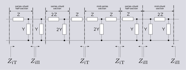
The sections of the hypothetical infinite filter are made of series elements having impedance 2Z and shunt elements with admittance 2Y. The factor of two is introduced for mathematical convenience, since it is usual to work in terms of half-sections where it disappears. The image impedance of the input and output port of a section will generally not be the same. However, for a mid-series section (that is, a section from halfway through a series element to halfway through the next series element) will have the same image impedance on both ports due to symmetry. This image impedance is designated
ZiTdue to the "T" topology of a mid-series section. Likewise, the image impedance of a mid-shunt section is designatedZiΠdue to the "Π" topology. Half of such a"T"or"Π"section is called a half-section, which is also an L-section but with half the element values of the full L-section. The image impedance of the half-section is dissimilar on the input and output ports: on the side presenting the series element it is equal to the mid-seriesZiT, but on the side presenting the shunt element it is equal to the mid-shuntZiΠ. There are thus two variant ways of using a half-section.- Parts of this article or section rely on the reader's knowledge of the complex impedance representation of capacitors and inductors and on knowledge of the frequency domain representation of signals.
Derivation
 Constant k low-pass filter half section. Here inductance L is equal Ck2
 Constant k band-pass filter half section.
L1 = C2k2 and L2 = C1k2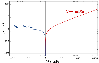 Image impedance ZiT of a constant k prototype low-pass filter is plotted vs. frequency ω. The impedance is purely resistive (real) below ωc, and purely reactive (imaginary) above ωc.
The building block of constant k filters is the half-section "L" network, composed of a series impedance Z, and a shunt admittance Y. The "k" in "constant k" is the value given by,[6]
Thus, k will have units of impedance, that is, ohms. It is readily apparent that in order for k to be constant, Y must be the dual impedance of Z. A physical interpretation of k can be given by observing that k is the limiting value of Zi as the size of the section (in terms of values of its components, such as inductances, capacitances, etc.) approaches zero, while keeping k at its initial value. Thus, k is the characteristic impedance, Z0, of the transmission line that would be formed by these infinitesimally small sections. It is also the image impedance of the section at resonance, in the case of band-pass filters, or at ω = 0 in the case of low-pass filters.[7] For example, the pictured low-pass half-section has
 .
.
Elements L and C can be made arbitrarily small while retaining the same value of k. Z and Y however, are both approaching zero, and from the formulae (below) for image impedances,
 .
.
Image impedance
- See also Image impedance#Derivation
The image impedances of the section are given by[8]
and
Provided that the filter does not contain any resistive elements, the image impedance in the pass band of the filter is purely real and in the stop band it is purely imaginary. For example, for the pictured low-pass half-section,[9]
The transition occurs at a cut-off frequency given by
Below this frequency, the image impedance is real,
Above the cut-off frequency the image impedance is imaginary,
Transmission parameters
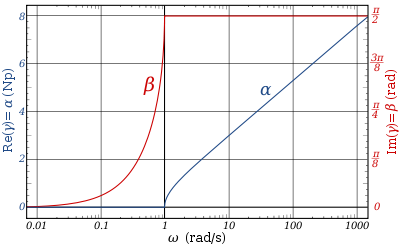 The transfer function of a constant k prototype low-pass filter for a single half-section showing attenuation in nepers and phase change in radians.See also: Image impedance#Transfer function
The transmission parameters for a general constant k half-section are given by[10]
and for a chain of n half-sections
For the low-pass L-shape section, below the cut-off frequency, the transmission parameters are given by[8]
That is, the transmission is lossless in the pass-band with only the phase of the signal changing. Above the cut-off frequency, the transmission parameters are:[8]
Prototype transformations
The presented plots of image impedance, attenuation and phase change correspond to a low-pass prototype filter section. The prototype has a cut-off frequency of ωc = 1 rad/s and a nominal impedance k = 1 Ω. This is produced by a filter half-section with inductance L = 1 henry and capacitance C = 1 farad. This prototype can be impedance scaled and frequency scaled to the desired values. The low-pass prototype can also be transformed into high-pass, band-pass or band-stop types by application of suitable frequency transformations.[11]
Cascading sections
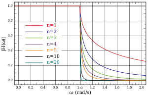 Gain response, H(ω) for a chain of n low-pass constant-k filter half-sections.
Several L-shape half-sections may be cascaded to form a composite filter. Like impedance must always face like in these combinations. There are therefore two circuits that can be formed with two identical L-shaped half-sections. Where a port of image impedance Z
iTfaces another ZiT, the section is called aΠsection. Where ZiΠfaces ZiΠthe section so formed is a T section. Further additions of half-sections to either of these section forms a ladder network which may start and end with series or shunt elements.[12]It should be borne in mind that the characteristics of the filter predicted by the image method are only accurate if the section is terminated with its image impedance. This is usually not true of the sections at either end, which are usually terminated with a fixed resistance. The further the section is from the end of the filter, the more accurate the prediction will become, since the effects of the terminating impedances are masked by the intervening sections.[13]
Image filter sections Unbalanced L Half section T Section Π Section 


Ladder network 
Balanced C Half-section H Section Box Section 


Ladder network 
X Section (mid-T-Derived) X Section (mid-Π-Derived) 
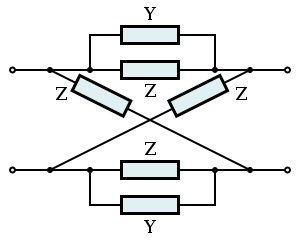
N.B. Textbooks and design drawings usually show the unbalanced implementations, but in telecoms it is often required to convert the design to the balanced implementation when used with balanced lines. edit See also
Notes
- ^ Campbell, G. A. (November 1922), "Physical Theory of the Electric Wave-Filter", Bell System Tech J 1 (2): 1–32
- ^ Bray, p.62 gives 1910 as the start of Campbell's work on filters.
- ^ White, G. (January 2000), "The Past", BT Technology Journal 18 (1): 107–132, doi:10.1023/A:1026506828275
- ^ Bray, p.62.
- ^ Zobel, O J, Multiple-band wave filter, U.S. Patent 1,509,184, filed 30 April 1920, issued 23 Sept 1924.
- ^ Zobel, 1923, p.6.
- ^ Zobel, 1923, pp.3-4.
- ^ a b c Matthaei et al., p.61.
- ^ Matthaei et al., pp.61-62.
- ^ Zobel, 1923, p.3.
- ^ Matthaei et al., pp.96-97, 412-413, 438-440, 727-729.
- ^ Matthaei et al., pp.65-68.
- ^ Matthaei et al., p.68.
References
- Bray, J., Innovation and the Communications Revolution, Institute of Electrical Engineers, 2002.
- Matthaei, G.; Young, L.; Jones, E. M. T., Microwave Filters, Impedance-Matching Networks, and Coupling Structures McGraw-Hill 1964.
- Zobel, O. J.,Theory and Design of Uniform and Composite Electric Wave Filters, Bell Systems Technical Journal, Vol. 2 (1923), pp. 1-46.
Further reading
- For a simpler treatment of the analysis see,
- Ghosh, Smarajit (2005), Network Theory: Analysis and Synthesis, New Delhi: Prentice Hall of India, pp. 544–563, ISBN 8120326385, http://books.google.com/?id=bYbP7rfG2YYC&pg=RA1-PA544
Categories:- Image impedance filters
- Analog circuits
- Electronic filter topology


Wikimedia Foundation. 2010.