- mm'-type filter
-
Linear analog electronic filters - Constant k filter
- m-derived filter
- General image filters
- Zobel network (constant R) filter
- Lattice filter (all-pass)
- Bridged T delay equaliser (all-pass)
- Composite image filter
- mm'-type filter
Simple filtersedit mm'-type filters, also called double-m-derived filters, are a type of electronic filter designed using the image method. They were patented by Otto Zobel in 1932.[1] Like the m-type filter from which it is derived, the mm'-type filter type was intended to provide an improved impedance match into the filter termination impedances and originally arose in connection with telephone frequency division multiplexing. The filter has a similar transfer function to the m-type, having the same advantage of rapid cut-off, but the input impedance remains much more nearly constant if suitable parameters are chosen. In fact, the cut-off performance is better for the mm'-type if like-for-like impedance matching are compared rather than like-for-like transfer function. It also has the same drawback of a rising response in the stopband as the m-type. However, its chief disadvantage is its much increased complexity which is the chief reason its use never became widespread. It was only ever intended to be used as the end sections of a composite filters, the rest of the filter being made up of other sections such as k-type and m-type sections.
An incidental advantage of the mm'-type is that it has two independent parameters (m and m') that the designer can adjust. This allows for two different design criteria to be independently optimised.
Contents
- Parts of this article or section rely on the reader's knowledge of the complex impedance representation of capacitors and inductors and on knowledge of the frequency domain representation of signals.
Background
The mm'-type filter was an extension of Zobel's previous m-type filter, which itself grew out of George Campbell's k-type design. Zobel's m-type is arrived at by applying the m-derivation process (see m-derived filter) to the k-type filter. Completely analogously, the mm'-type is arrived at by applying the m-derived process to the m-type filter. The value of m used in the second transformation is designated m' to distinguish it from m, hence the naming of the filter mm'-type. However, this filter is not a member of the class of filters, general mn-type image filters, which are a generalisation of m-type filters. Rather, it is a double application of the m-derived process and for those filters the arbitrary parameters are usually designated m1, m2, m3 etc., rather than m, m', m'' as here.
The importance of the filter lies in its impedance properties. Some of the impedance terms and section terms used in image design theory are pictured in the diagram below. As always, image theory defines quantities in terms of an infinite cascade of two-port sections, and in the case of the filters being discussed, an infinite ladder network of L-sections.
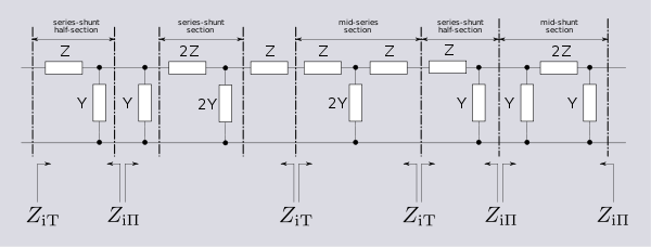
The sections of the hypothetical infinite filter are made up of series impedance elements of 2Z and shunt admittance elements of 2Y. The factor of two is introduced since it is normal to work in terms of half-sections where it disappears. The image impedance of the input and output port of a section,
Zi1andZi2, will generally not be the same. However, for a mid-series section (that is, a section from halfway through a series element to halfway through the next series element) will have the same image impedance on both ports due to symmetry. This image impedance is designatedZiTdue to the "T" topology of a mid-series section. Likewise, the image impedance of a mid-shunt section is designatedZiΠdue to the "Π" topology. Half of such a"T"or"Π"section is (unsurprisingly) called a half-section. The image impedances of the half section are dissimilar on the input and output ports but are equal to the mid-seriesZiTon the side presenting the series element and the mid-shuntZiΠon the side presenting the shunt element.A mid-series derived section (that is, a series m-type filter) has precisely the same image impedance,
ZiT, as a k-type mid-series "T" filter. However, the image impedance of a half-section of such a filter (on the shunt side) is not the same and is designatedZiΠm. Similarly, the series element side of a shunt m-derived filter half-section is designatedZiTm.Derivation
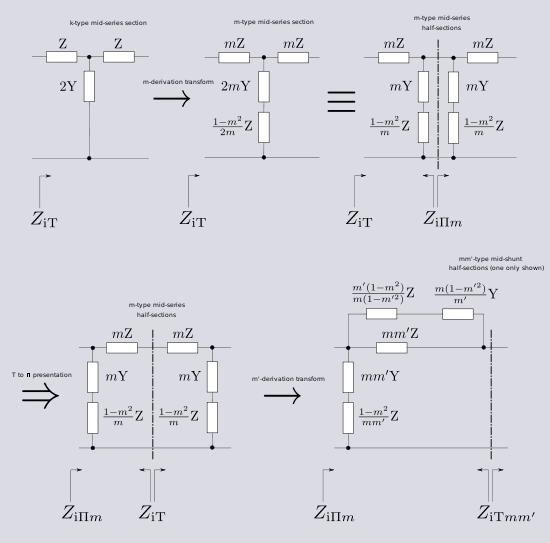 Derivation of a mm'-type mid-shunt filter section. Starting from a prototype constant k filter T-filter, the circuit is transformed to a m-type mid-series derived filter, re-implemented as Π-section, transformed again to a mid-shunt derived mm'-type.
The m-derived process starts with a k-type filter mid-section and transforms it into a m-derived filter with a different transfer function but retaining the same image impedance and passband. Two different results are obtained depending on whether the process began with a T-section or a Π-section. From a T-section, the series Z and shunt Y are multiplied by an arbitrary parameter m (0 < m < 1). An additional impedance is then inserted in series with Y whose value is that which restores the original image impedance. The half-sections resulting from splitting the T-section, however, will show a different image impedance at the split,
ZiΠm. Two such half-sections cascaded with theZiTimpedances facing, will form aΠ-section with image impedanceZiΠm. The m-derived process can now be applied to this new section, but with a new parameter m'. The series Z and shunt Y are multiplied by m' and an additional admittance is inserted in parallel with the series elements to bring the image impedance back to its original value ofZiΠm. Again, the half sections will have a different image impedance at the split ports and this is designatedZiTmm'.The dual realisation of this filter is obtained in a completely analogous way by first transforming a mid-shunt k-type Π-section, forming the resulting mid-series m-type T-section and then transforming using m', resulting in a new Π flavour of
Zimm',ZiΠmm', which is the dual ofZiTmm'.The m-derivation transformation can, in principle, be applied ad-infinitum and produce mm'm''-types etc. There is, however, no practical benefit in doing this. The improvements obtained diminish at each iteration and are not worth the increase in complexity. Note that applying the m-derived transformation twice to a T-section (or Π-section) will merely result in an m-type filter with a different value of m. The transformation must be applied alternately to T-sections and Π-sections for a completely new form of filter to be obtained.
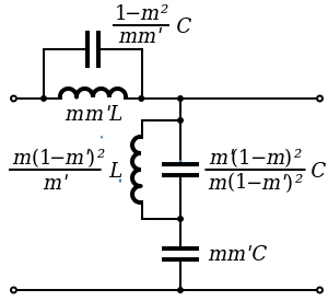 mm'-type low-pass filter series half section. C = L/R02
Operating frequency
For a low-pass prototype, the cut-off frequency is given by the same expression as for the m-type and the k-type;
The pole of attenuation occurs at;
Image impedance
- See also Image impedance#Derivation
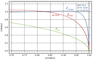 Image impedance plot of an optimised mm'-type shunt section (ZiTmm', in blue) compared with an m-derived prototype shunt image impedance (ZiTm, in red) for m = 0.6. A constant-k filter's image impedance is also shown (ZiT, in green).
The following expressions for image impedances are all referenced to the low-pass prototype section. They are scaled to the nominal impedance R0 = 1 and the frequencies in those expressions are all scaled to the cut-off frequency ωc = 1.
"T" port image impedance
The image impedance looking into a "T" topology port of a shunt derived section is given by,
For comparison;
 and
and 
"Π" port image impedance
The image impedance looking into a "Π" topology port of a series derived section is given by,
For comparison;
 and
and 
Optimisation
Note that
 can be adjusted independently of m by adjusting m'. It is therefore possible to adjust the impedance characteristic and frequency response characteristic independently. However, for optimum impedance match it is necessary to adjust both parameters solely for maximally flat image resistance in the passband. The term resistance is used because the image impedance is purely real in the passband between cut-off frequencies and purely imaginary outside the passband. It is not possible to obtain an exact impedance match across the entire band. With two degrees of freedom it is only possible to match the impedance exactly at two spot frequencies. It has been determined empirically[1] that a good match is made with the values;
This amounts to setting the match to be exact at frequencies 0.8062 and 0.9487 rad/s for the prototype filter and the impedance departs less than 2% from nominal from 0 to 0.96 rad/s, that is, nearly all of the passband.
The transfer function of an mm'-type is the same as an m-type with m set to the product mm' and in this case mm'=0.3. Where an m-type section is used for impedance matching the optimum value of m is m=0.6. Steepness of cut-off increases with decreasing m so an mm'-type section has this as an incidental advantage over an m-type in this application.
Transmission parameters
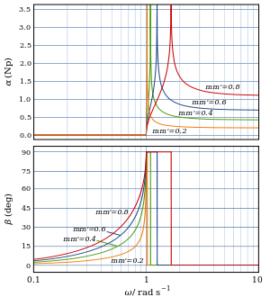 mm'-type low-pass filter transfer function for a single half-section with various values of mm'

- See also Image impedance#Transfer function
The operating frequencies, transmission parameters and transfer function are identical to those for the m-type and details can be found in that article if the parameter m is replaced by the product mm'. Only the image impedance is different in the mm'-type filter in terms of black box behaviour.
Prototype transformations
The plots shown of image impedance and attenuation are the plots of a low-pass prototype filter section. The prototype has a cut-off frequency of ωc=1 rad/s and a nominal impedance R0=1Ω. This is produced by a filter half-section where L=1 henry and C=1 farad. This prototype can be impedance scaled and frequency scaled to the desired values. The low-pass prototype can also be transformed into high-pass, band-pass or band-stop types by application of suitable frequency transformations.
Cascading sections
As with all image filters, it is required to match each section into a section of identical image impedance if the theoretical filter response is to be achieved. This is a particular difficulty for the end sections of the filter which are often working into resistive terminations which cannot be matched exactly by an image impedance. Hence the use of the mm'-type as end sections for the filter because of its nearly flat impedance with frequency characteristic in the passband. However, it is not desirable to use it throughout the entire filter. The workhorse of image filters are the k-type sections and these will usually be required somewhere in the filter for good rejection in the stopband well away from cut-off and also because they are the simplest topology and lowest component count. Unfortunately, neither side of a mm'-type can match into a k-type. The solution is to form a composite section from a mm'-type half-section and a m-type section which will match each other on one side if m has the same value for both half-sections. This can, for instance, produce a composite T-section with
ZiTmm'facing the termination andZiTfacing the rest of the filter. The T-section will be matched internally withZiTm. This has the additional incidental advantage of producing two poles of attenuation in the stopband at different frequencies. This is a consequence of m and mm' necessarily being different values.Image filter sections Unbalanced L Half section T Section Π Section 


Ladder network 
Balanced C Half-section H Section Box Section 


Ladder network 
X Section (mid-T-Derived) X Section (mid-Π-Derived) 

N.B. Textbooks and design drawings usually show the unbalanced implementations, but in telecoms it is often required to convert the design to the balanced implementation when used with balanced lines. edit See also
- Image impedance
- Constant k filter
- m-derived filter
- General mn-type image filters
- Composite image filter
References
-
- Zobel, O. J.,Theory and Design of Uniform and Composite Electric Wave Filters, Bell Systems Technical Journal, Vol. 2 (1923), pp. 1-46.
- Mathaei, Young, Jones Microwave Filters, Impedance-Matching Networks, and Coupling Structures McGraw-Hill 1964.
- Mole, J H, Filter Design Data for Communication Engineers, London: E & F N Spon Ltd.,1952 OCLC 247417663.
Categories:- Image impedance filters
- Analog circuits
- Electronic design
- Electronic filter topology


Wikimedia Foundation. 2010.