- Composite image filter
-
Linear analog electronic filters Image impedance filters- Constant k filter
- m-derived filter
- General image filters
- Zobel network (constant R) filter
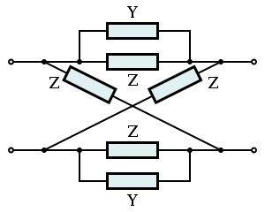
- Lattice filter (all-pass)
- Bridged T delay equaliser (all-pass)
- Composite image filter
- mm'-type filter
Simple filtersedit A composite image filter is an electronic filter consisting of multiple image filter sections of two or more different types.
The image method of filter design determines the properties of filter sections by calculating the properties they have in an infinite chain of such sections. In this, the analysis parallels transmission line theory on which it is based. Filters designed by this method are called image parameter filters, or just image filters. An important parameter of image filters is their image impedance, the impedance of an infinite chain of identical sections.
The basic sections are arranged into a ladder network of several sections, the number of sections required is mostly determined by the amount of stopband rejection required. In its simplest form, the filter can consist entirely of identical sections. However, it is more usual to use a composite filter of two or three different types of section to improve different parameters best addressed by a particular type. The most frequent parameters considered are stopband rejection, steepness of the filter skirt (transition band) and impedance matching to the filter terminations.
Image filters are linear filters and are invariably also passive in implementation.
Contents
History
The image method of designing filters originated at AT&T, who were interested in developing filtering that could be used with the multiplexing of many telephone channels on to a single cable. The researchers involved in this work and their contributions are briefly listed below;
- John Carson provided the mathematical underpinning to the theory. He invented single sideband modulation for the purpose of multiplexing telephone channels. It was the need to recover these signals that gave rise to the need for advanced filtering techniques. He also pioneered the use of operational calculus (what has now become Laplace transforms in its more formal mathematical guise) to analyse these signals.[1]
- George Campbell worked on filtering from 1910 onwards and invented the constant k filter.[2] This can be seen as a continuation of his work on loading coils on transmission lines, a concept invented by Oliver Heaviside. Heaviside, incidentally, also invented the operational calculus used by Carson.
- Otto Zobel provided a theoretical basis (and the name) for Campbell's filters. In 1920 he invented the m-derived filter. Zobel also published composite designs incorporating both constant k and m-derived sections.[3]
- R S Hoyt also contributed.[4][5]
The image method
Main article: Image impedanceThe image analysis starts with a calculation of the input and output impedances (the image impedances) and the transfer function of a section in an infinite chain of identical sections. This can be shown to be equivalent to the performance of a section terminated in its image impedances.[6] The image method, therefore, relies on each filter section being terminated with the correct image impedance. This is easy enough to do with the internal sections of a multiple section filter, because it is only necessary to ensure that the sections facing the one in question have identical image impedances. However, the end sections are a problem. They will usually be terminated with fixed resistances that the filter cannot match perfectly except at one specific frequency. This mismatch leads to multiple reflections at the filter terminations and at the junctions between sections. These reflections result in the filter response deviating quite sharply from the theoretical, especially near the cut-off frequency.[7]
The requirement for better matching to the end impedances is one of the main motivations for using composite filters. A section designed to give good matching is used at the ends but something else (for instance stopband rejection or passband to stopband transition) is designed for the body of the filter.
Filter section types
Each filter section type has particular advantages and disadvantages and each has the capability to improve particular filter parameters. The sections described below are the prototype filters for low-pass sections. These prototypes may be scaled and transformed to the desired frequency bandform (low-pass, high-pass, band-pass or band-stop).
The smallest unit of an image filter is an L half-section. Because the L section is not symmetrical, it has different image impedances (
 ) on each side. These are denoted
  and
and  . The T and the Π in the suffix refer to the shape of the filter section that would be formed if two half sections were to be connected back-to-back. T and Π are the smallest symmetrical sections that can be constructed, as shown in diagrams in the topology chart (below). Where the section in question has an image impedance different from the general case a further suffix is added identifying the section type, for instance
  .
.Image filter sections Unbalanced L Half section T Section Π Section 


Ladder network 
Balanced C Half-section H Section Box Section 


Ladder network 
X Section (mid-T-Derived) X Section (mid-Π-Derived) 
N.B. Textbooks and design drawings usually show the unbalanced implementations, but in telecoms it is often required to convert the design to the balanced implementation when used with balanced lines. edit Constant k section
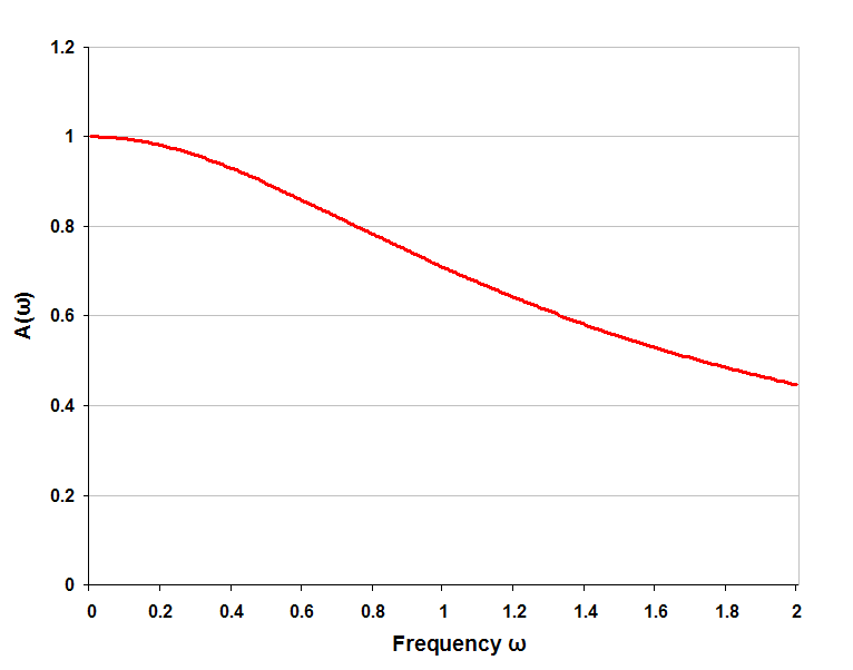
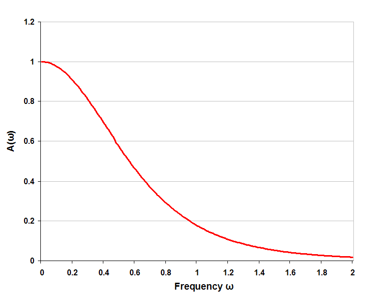
Main article: Constant k filterThe constant k or k-type filter section is the basic image filter section. It is also the simplest circuit topology. The k-type has moderately fast transition from the passband to the stopband and moderately good stopband rejection.
-

k-type low-pass filter half section
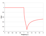
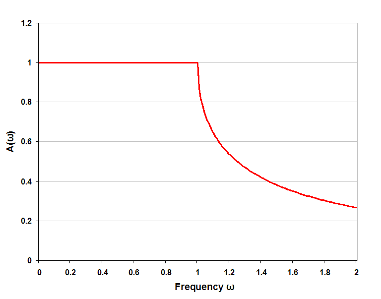
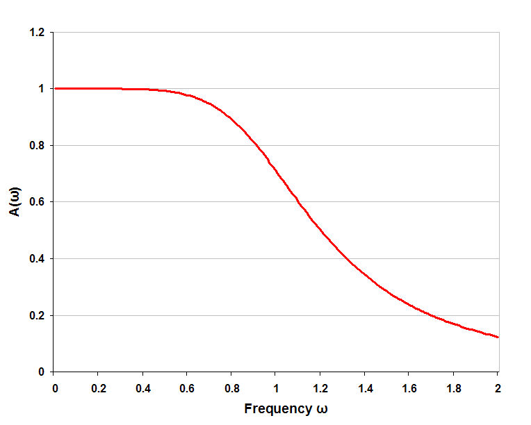
-

k-type low-pass response, single half-section
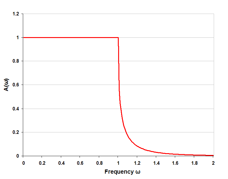
-

k-type low-pass response with four (half) sections
m-derived section
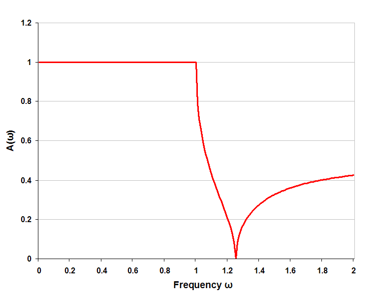
Main article: m-derived filterThe m-derived or m-type filter section is a development of the k-type section. The most prominent feature of the m-type is a pole of attenuation just past the cut-off frequency inside the stopband. The parameter m (0<m<1) adjusts the position of this pole of attenuation. Smaller values of m put the pole closer to the cut-off frequency. Larger values of m put it further away. In the limit, as m approaches unity, the pole approaches ω of infinity and the section approaches a k-type section.
The m-type has a particularly fast cut-off, going from fully pass at the cut-off frequency to fully stop at the pole frequency. The cut-off can be made faster by moving the pole nearer to the cut-off frequency. This filter has the fastest cut-off of any filter design; note that the fast transition is achieved with just a single section, there is no need for multiple sections. The drawback with m-type sections is that they have poor stopband rejection past the pole of attenuation.
There is a particularly useful property of m-type filters with m=0.6. These have maximally flat image impedance
 in the passband. They are therefore good for matching in to the filter terminations, in the passband at least, the stopband is another story.
There are two variants of the m-type section, series and shunt. They have identical transfer functions but their image impedances are different. The shunt half-section has an image impedance which matches
on one side but has a different impedance, on the other. The series half-section matches on one side and has  on the other.
-

m-type low-pass filter shunt half section
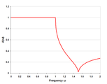
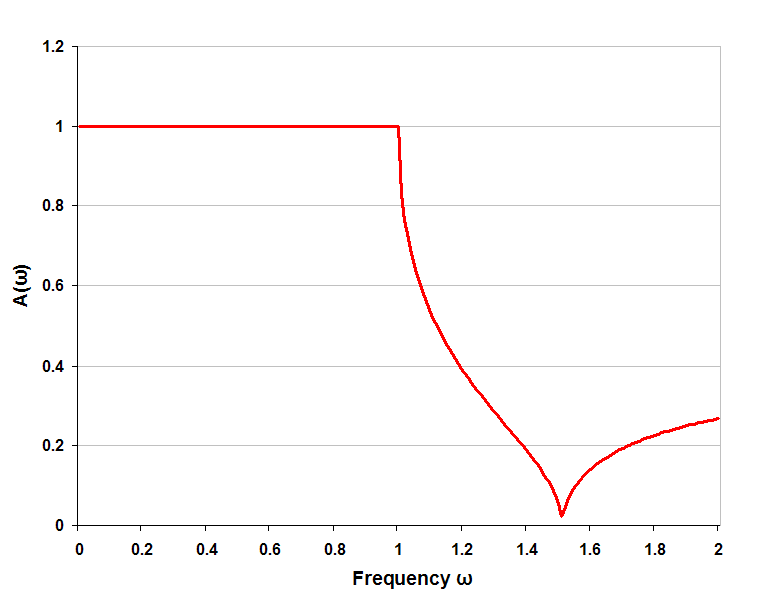
-
m-type low-pass response single half-section m=0.5
-

m-type low-pass response with four (half) sections m=0.5
-

m-type low-pass filter series half section
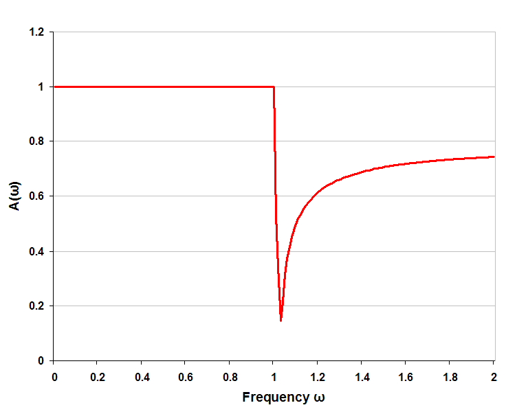
-
m-type low-pass response single half-section m=0.75
-

m-type low-pass response single half-section m=0.25
mm'-type section
Main article: mm'-type filterThe mm'-type section has two independent parameters (m and m') that the designer can adjust. It is arrived at by double application of the m-derivation process. Its chief advantage is that it rather better at matching in to resistive end terminations than the k-type or m-type. The image impedance of a half-section is
on one side and a different impedance,  on the other. Like the m-type, this section can be constructed as a series or shunt section and the image impedances will come in T and Π variants. Either a series construction is applied to a shunt m-type or a shunt construction is applied to a series m-type. The advantages of the mm'-type filter are achieved at the expense of greater circuit complexity so it would normally only be used where it is needed for impedance matching purposes and not in the body of the filter.
The transfer function of an mm'-type is the same as an m-type with m set to the product mm'. To choose values of m and m' for best impedance match requires the designer to choose two frequencies at which the match is to be exact, at other frequencies there will be some deviation. There is thus some leeway in the choice but Zobel suggests[8] the values m=0.7230 and m'=0.4134 which give a deviation of the impedance of less than 2% over the useful part of the band. Since mm'=0.3, this section will also have a much faster cut-off than an m-type of m=0.6 which is an alternative for impedance matching.
It is possible to continue the m-derivation process repeatedly and produce mm'm''-types and so on. However, the improvements obtained diminish at each iteration and are not usually worth the increase in complexity.
-

mm'-type low-pass filter series half section
-

m-type low-pass response single half-section m=0.6
-

mm'-type low-pass response single half-section mm'=0.3
Bode's filter
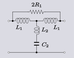 One incarnation of Bode's filter as a low-pass filter.
Another variation on the m-type filter was described by Hendrik Bode. This filter uses as a prototype a mid-series m-derived filter and transforms this into a bridged-T topology with the addition of a bridging resistor. This section has the advantage of being able to place the pole of attenuation much closer to the cut-off frequency than the Zobel filter, which starts to fail to work properly with very small values of m because of inductor resistance. See equivalent impedance transforms for an explanation of its operation.[9]
Zobel network
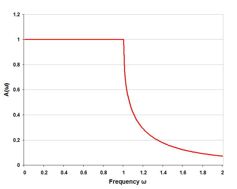
Main article: Zobel networkThe distinguishing feature of Zobel network filters is that they have a constant resistance image impedance and for this reason are also known as constant resistance networks. Clearly, the Zobel network filter does not have a problem matching to its terminations and this is its main advantage. However, other filter types have steeper transfer functions and sharper cut-offs. In filtering applications, the main role of Zobel networks is as equalisation filters. Zobel networks are in a different group from other image filters. The constant resistance means that when used in combination with other image filter sections the same problem of matching arises as with end terminations. Zobel networks also suffer the disadvantage of using far more components than other equivalent image sections.
-

Zobel network bridge T high-pass filter section
-
Zobel network low-pass response single section
-

Zobel network low-pass response five sections
Effect of end terminations
Main article: Image filter end terminationsA consequence of the image method of filter design is that the effect of the end terminations has to be calculated separately if its effects on response are to be taken into account. The most severe deviation of the response from that predicted occurs in the passband close to cut-off. The reason for this is twofold. Further into the passband the impedance match progressively improves, thus limiting the error. On the other hand, waves in the stopband are reflected from the end termination due to mismatch but are attenuated twice by the filter stopband rejection as they pass through it. So while stopband impedance mismatch may be severe, it has only limited effect on the filter response.
-

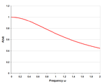
Theoretical k-type low-pass T-filter (two half-sections) response when correctly terminated in image impedance
-

Practical k-type low-pass T-filter (two half-sections) response when terminated with fixed resistors
Cascading sections
Several L half-sections may be cascaded to form a composite filter. The most important rule when constructing a composite image filter is that the image impedances must always face an identical impedance; like must always face like. T sections must always face T sections, Π sections must always face Π sections, k-type must always face k-type (or the side of an m-type which has the k-type impedance) and m-type must always face m-type. Furthermore, m-type impedances of different values of m cannot face each other. Nor can sections of any type which have different values of cut-off frequency.
Sections at the beginning and end of the filter are often chosen for their impedance match in to the terminations rather than the shape of their frequency response. For this purpose, m-type sections of m = 0.6 are the most common choice.[10] An alternative is mm'-type sections of m=0.7230 and m'=0.4134 although this type of section is rarely used. While it has several advantages noted below, it has the disadvantages of being more complex and also, if constant k sections are required in the body of the filter, it is then necessary to include m-type sections to interface the mm'-type to the k-types.[11]
The inner sections of the filter are most commonly chosen to be constant k since these produce the greatest stopband attenuation. However, one or two m-type sections might also be included to improve the rate of fall from pass to stopband. A low value of m is chosen for m-types used for this purpose. The lower the value of m, the faster the transition, while at the same time, the stopband attenuation becomes less, increasing the need to use extra k-type sections as well. An advantage of using mm'-types for impedance matching is that these type of end sections will have a fast transition anyway (much more so than m=0.6 m-type) because mm'=0.3 for impedance matching. So the need for sections in the body of the filter to do this may be dispensed with.
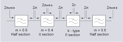 Typical example of a composite image filter in block diagram form. The image impedances and how they match are shown.
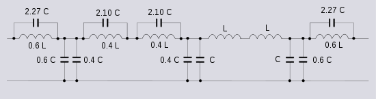 The above filter realised as a ladder low-pass filter. Component values are given in terms of L and C, the component values of a constant k half-section.
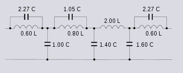 The same filter minimised by combining components in series or parallel where appropriate.
Another reason for using m-types in the body of the filter is to place an additional pole of attenuation in the stopband. The frequency of the pole directly depends on the value of m. The smaller the value of m, the closer the pole is to the cut-off frequency. Conversely, a large value of m places the pole further away from cut-off until in the limit when m=1 the pole is at infinity and the response is the same as the k-type section. If a value of m is chosen for this pole which is different from the pole of the end sections it will have the effect of broadening the band of good stopband rejection near to the cut-off frequency. In this way the m-type sections serve to give good stopband rejection near to cut-off and the k-type sections give good stopband rejection far from cut-off. Alternatively, m-type sections can be used in the body of the filter with different values of m if the value found in the end sections is unsuitable. Here again, the mm'-type would have some advantages if used for impedance matching. The mm'-type used for impedance matching places the pole at m=0.3. However, the other half of the impedance matching section needs to be an m-type of m=0.723.[8] This automatically gives a good spread of stopband rejection and as with the steepness of transition issue, use of mm'-type sections may remove the need for additional m-type sections in the body.
Constant resistance sections may also be required, if the filter is being used on a transmission line, to improve the flatness of the passband response. This is necessary because the transmission line response is not usually anywhere near perfectly flat. These sections would normally be placed closest to the line since they present a predictable impedance to the line and also tend to mask the indeterminate impedance of the line from the rest of the filter. There is no issue with matching constant resistance sections to each other even when the sections are operating on totally different frequency bands. All sections can be made to have precisely the same image impedance of a fixed resistance.
See also
Image filter types
- Constant k filter
- m-derived filter
- General mn-type image filters
- mm'-type filter
- Zobel network
- Lattice filter
Design concepts
- Image impedance
- Prototype filter
- Loading coils
People
- Otto Zobel
- George Campbell
- John Renshaw Carson
- Oliver Heaviside
References
Bibliography
- Campbell, G A, "Physical theory of the electric wave-filter", Bell System Tech J, November 1922, vol 1, no 2, pp 1–32.
- Bode, Hendrik W., Wave Filter, US patent 2 002 216, filed 7 June 1933, issued 21 May 1935.
- Bray, J, Innovation and the Communications Revolution, Institute of Electrical Engineers ISBN 0852962185.
- Carson, J R, Electric Circuit Theory and Operational Calculus, 1926, McGraw-Hill, New York.
- Laplante, Phillip A, Comprehensive Dictionary of Electrical Engineering, CRC Press, 2005 ISBN 0849330866.
- Lee, Thomas H, Planar Microwave Engineering: a Practical Guide to Theory, Measurement, and Circuits, Cambridge University Press, 2004 ISBN 0521835267.
- Matthaei, Young, Jones Microwave Filters, Impedance-Matching Networks, and Coupling Structures McGraw-Hill 1964
- Mole, J H, Filter Design Data for Communication Engineers, London: E & F N Spon Ltd.,1952 OCLC 247417663.
- White, G, "The Past", Journal BT Technology, Vol 18, No 1, pp. 107–132, January 2000, Springer Netherlands.
- Zobel, O J,"Theory and design of uniform and composite electric wave filters", Bell Systems Technical Journal, vol.2 (1923), pp. 1–46.
- Zobel, O J, Electrical wave filters, US patent 1 850 146, filed 25 November 1930, issued 22 March 1932.
- Redifon Radio Diary, 1970, pp. 45–48, William Collins Sons & Co, 1969.
Categories:- Linear filters
- Image impedance filters
- Filter theory
- Analog circuits
- Electronics terms
- Electronic design


Wikimedia Foundation. 2010.