- Dual impedance
-
Dual impedance and dual network are terms used in electronic network analysis. The dual of an impedance
 is its algebraic inverse
  . Note that
  and
and  are the duals of each other, that is, they are reciprocal. For this reason the dual impedance is also called the inverse impedance. The dual of a network of impedances is that network whose impedance is
  . In the case of a network with more than one port the impedance looking into each of the ports must simultaneously be dual.
Another way of stating this is that the dual of is the admittance  .
.
This is consistent with the definition of dual as being that circuit whose voltages and currents are interchanged since and
and 
Contents
- Parts of this article or section rely on the reader's knowledge of the complex impedance representation of capacitors and inductors and on knowledge of the frequency domain representation of signals.
Scaled and normalised duals
In a real design situation it is usually desired to find the dual of an impedance with respect to some nominal or characteristic impedance. To do this, Z and Z' are scaled to the nominal impedance Z0 so that;

Z0 is usually taken to be a purely real number R0, so Z' is only changed by a real factor of R02. In other words, the dual remains qualitatively the same circuit but all the component values must be scaled quantitively by R02.
Duals of basic circuit elements
Element Z Dual Z' 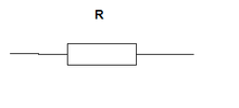 Resistor R

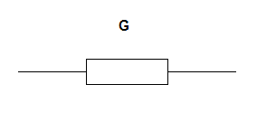
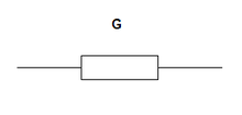 Conductor G = R
 Conductor G
 Resistor R = G
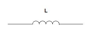
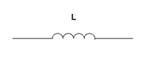 Inductor L
 Capacitor C = L
 Capacitor C
 Inductor L = C
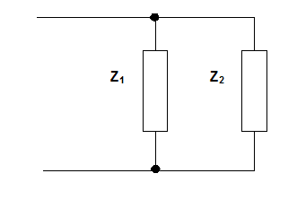
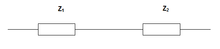 Series impedances Z = Z1 + Z2
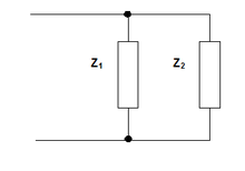 Parallel admittances Y = Z1 + Z2
 Parallel impedances 1/Z = 1/Z1 + 1/Z2
 Series admittances 1/Y = 1/Z1 + 1/Z2
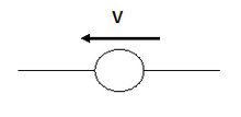 Voltage generator V
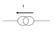 Current generator I = V
Current generator I
Voltage generator V = I
Current generator I = V
Current generator I
Voltage generator V = IGraphical Method
There is a graphical method of obtaining the dual of a network which is often easier to use than the mathematical expression for the impedance. Starting with a circuit diagram of the network in question, Z, the following steps are drawn on the diagram to produce Z' superimposed on top of Z. Typically, Z' will be drawn in a different colour to help distinguish it from the original, or, if using CAD, Z' can be drawn on a different layer.
- A generator is connected to each port of the original network. The purpose of this step is to prevent the ports from being "lost" in the inversion process. This happens because a port left open circuit will transform into a short circuit and disappear.
- A dot is drawn at the centre of each mesh of the network Z. These dots will become the circuit nodes of Z'.
- A conductor is drawn which entirely encloses the network Z. This conductor also becomes a node of Z'.
- For each circuit element of Z, its dual is drawn between the nodes in the centre of the meshes either side of Z. Where Z is on the edge of the network, one of these nodes will be the enclosing conductor from the previous step.
This completes the drawing of Z'. This method also serves to demonstrate that the dual of a mesh transforms in to a node and the dual of a node transforms in to a mesh. Two useful examples are given below, both to illustrate the process and to give some further examples of dual networks.
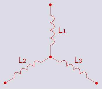
Example - star network
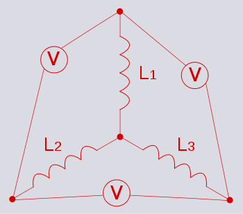 Attaching generators to the three ports
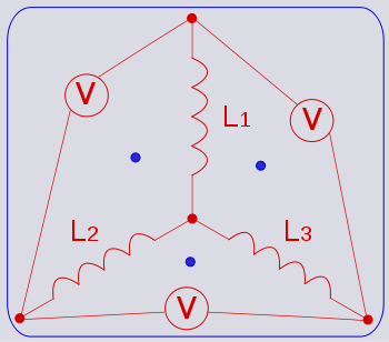 Nodes of the dual network
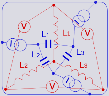 Components of the dual network
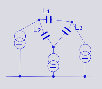 The dual network with the original removed and slightly redrawn to make the topology clearer
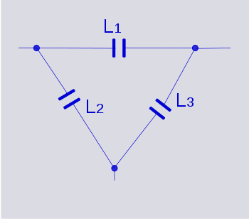 The dual network with the notional generators removed
It is now clear that the dual of a star network of inductors is a delta network of capacitors. This dual circuit is not the same thing as a star-delta (Y-Δ) transformation. A Y-Δ transform results in an equivalent circuit, not a dual circuit.
Example - Cauer network
Filters designed using Cauer's topology of the first form are low-pass filters consisting of a ladder network of series inductors and shunt capacitors.
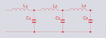 A low-pass filter implemented in Cauer topology
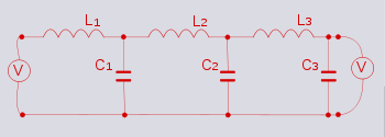 Attaching generators to the input and output ports
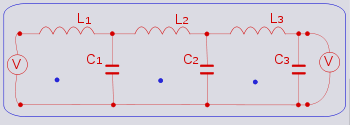 Nodes of the dual network
 Components of the dual network
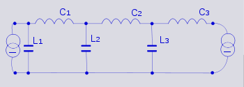 The dual network with the original removed and slightly redrawn to make the topology clearer
It can now be seen that the dual of a Cauer low-pass filter is still a Cauer low-pass filter. It does not transform into a high-pass filter as might have been expected. Note, however, that the first element is now a shunt component instead of a series component.
References
- Ghosh, Smarajit, Network Theory: Analysis and Synthesis, Prentice Hall of India
Categories: Analog circuits | Electronics terms | Filter theory | Electronic design


Wikimedia Foundation. 2010.