- Well logging
-
Well logging Gamma ray logging
Spontaneous potential logging
Resistivity logging
Density logging
Sonic logging
Caliper logging
Mud logging
LWD/MWD
Contents
Electric or geophysical well logs
The oil and gas industry records rock and fluid properties to find hydrocarbon zones in the geological formations intersected by a borehole. The logging procedure consists of lowering a 'logging tool' on the end of a wireline into an oil well (or hole) to measure the rock and fluid properties of the formation. An interpretation of these measurements is then made to locate and quantify potential depth zones containing oil and gas (hydrocarbons). Logging tools developed over the years measure the electrical, acoustic, radioactive, electromagnetic, nuclear magnetic resonance, and other properties of the rocks and their contained fluids. Logging is usually performed as the logging tools are pulled out of the hole. This data is recorded either at surface (real-time mode), or downhole (memory mode)to electronic data format and then either a printed record or electronic presentation called a "well log" provided to the client. Well logging is performed at various intervals during the drilling of the well and when the total depth is drilled, which could range in depths from 150 m to 10668 m (500 ft to 35,000 ft) or more.
Electric line is the common term for the armored, insulated cable used to conduct current to downhole tools used for well logging. Electric line can be subdivided into open hole operations and cased hole operations. Other conveyance methods for logging are logging while drilling (LWD), tractor, coiled tubing (real-time and memory), drill pipe conveyed, and slickline (memory, and with new development, some slickline telemetry capability).
Open hole operations, or reservoir evaluation, involve the deployment of tools into a freshly drilled well. As the toolstring traverses the wellbore, the individual tools gather information about the surrounding formations. A typical open hole log will have information about the density, porosity, permeability, lithology, presence of hydrocarbons, and oil and water saturation.
Cased hole operations, or production optimization, focus on optimizing the completed oil well through mechanical services and logging technologies. At this point in the well's life, the well is encased in steel pipe, cemented into the well bore and may or may not be producing. A typical cased hole log may show cement quality, production information, and formation data. Mechanical services use jet perforating guns, setting tools, and dump bailors to optimize the flow of hydrocarbons.
Wireline tool types
Typically the wireline tools are cylindrical in shape, usually from 1.5 to 5 inches in diameter. "Open hole" tool combinations can extend to over 100 feet long; "cased hole" tool combinations are often limited in length by the height restrictions imposed by constraints of "lubricator" pipe section required to contain the well pressure while deploying cased hole tools. There are many types of logging tools, ranging from common measurements (pressure and temperature) to advanced rock properties and fracture analysis, fluid properties in the wellbore, or formation properties extending several meters into the rock formation.
1. With sensors without excitation
- There are units to measure spontaneous potential (SP), which is a voltage difference between a surface electrode and another electrode located in the downhole instrument, other instruments that measure the natural radiation from natural isotopes of potassium, thorium, etc., to measure pressure and temperature, etc.
2. With sources of excitation and sensors
- There are sensor systems consistent with a source of excitation and a sensor. In this type we find acoustic (also called sonic), electric, inductive, magnetic resonance, sensing systems, just to name a few.
3. Instruments that produce some mechanical work, or retrieve a sample of fluid or rock to the surface.
- Devices to collect samples of rock, samples of fluid extracted from the rock, and some other mechanical devices.
Types of electric/electronic logs
There are many types of electric/electronic logs and they can be categorized either by their function or by the technology that they use. "Open hole logs" are run before the oil or gas well is lined with pipe or cased. "Cased hole logs" are run after the well is lined with casing or production pipe.[1]
Electric/electronic logs can also be divided into two general types based on what physical properties they measure. Resistivity logs measure some aspect of the specific resistance of the geologic formation. There are about 17 types of resistivity logs.
Porosity logs measure the fraction or percentage of pore volume in a volume of rock. Most porosity logs use either acoustic or nuclear technology. Acoustic logs measure characteristics of sound waves propagated through the well-bore environment. Nuclear logs utilize nuclear reactions that take place in the downhole logging instrument or in the formation. Nuclear logs include density logs and neutron logs, as well as gamma ray logs which are used for correlation. [2] The basic principle behind the use of nuclear technology is that a neutron source placed near the formation of which the porosity is required to be measured will result in neutrons being scattered by the hydrogen atoms, largely those present in the formation fluid. Since there is little difference in the neutrons scattered by hydrocarbons or water, the porosity measured gives a figure close to the true physical porosity whereas the figure obtained from electrical resistivity measurements is that due to the conductive formation fluid. The difference between neutron porosity and electrical porosity measurements therefore indicates the presence of hydrocarbons in the formation fluid.
History
Conrad and Marcel Schlumberger, who founded Schlumberger Limited in 1926, are considered the inventors of electric well logging. Conrad developed the Schlumberger array, which was a technique for prospecting for metal ore deposits, and the brothers adopted that surface technique to subsurface applications. On September 5, 1927, a crew working for Schlumberger lowered an electric sonde or tool down a well in Pechelbronn, Alsace, France creating the first well log. In modern terms, the first log was a resistivity log that could be described as 3.5-meter upside-down lateral log. [3]
In 1931, Henri George Doll and G. Dechatre, working for Schlumberger, discovered that the galvanometer wiggled even when no current was being passed through the logging cables down in the well. This led to the discovery of the spontaneous potential (SP) which was as important as the ability to measure resistivity. The SP effect was produced naturally by the borehole mud at the boundaries of permeable beds. By simultaneously recording SP and resistivity, loggers could distinguish between permeable oil-bearing beds and impermeable nonproducing beds [4].
In 1940, Schlumberger invented the spontaneous potential dipmeter; this instrument allowed the calculation of the dip and direction of the dip of a layer. The basic dipmeter was later enhanced by the resistivity dipmeter (1947) and the continuous resistivity dipmeter (1952).
Oil-based mud (OBM) was first used in Rangely Field, Colorado in 1948. Normal electric logs require a conductive or water-based mud, but OBMs are nonconductive. The solution to this problem was the induction log, developed in the late 1940s.
The introduction of the transistor and integrated circuits in the 1960s made electric logs vastly more reliable. Computerization allowed much faster log processing, and dramatically expanded log data-gathering capacity. The 1970s brought more logs and computers. These included combo type logs where resistivity logs and porosity logs were recorded in one pass in the borehole.
The two types of porosity logs (acoustic logs and nuclear logs) date originally from the 1940s. Sonic logs grew out of technology developed during World War II. Nuclear logging has supplemented acoustic logging, but acoustic or sonic logs are still run on some combination logging tools.
Nuclear logging was initially developed to measure the natural gamma radiation emitted by underground formations. However, the industry quickly moved to logs that actively bombard rocks with nuclear particles. The gamma ray log, measuring the natural radioactivity, was introduced by Well Surveys Inc. in 1939, and the WSI neutron log came in 1941. The gamma ray log is particularly useful as shale beds which often provide a relatively low permeability cap over hydrocarbon reservoirs usually display a higher level of gamma radiation. These logs were important because they can be used in cased wells (wells with production casing). WSI quickly became part of Lane-Wells. During World War II, the US Government gave a near wartime monopoly on open-hole logging to Schlumberger, and a monopoly on cased-hole logging to Lane-Wells[5]. Nuclear logs continued to evolve after the war.
The nuclear magnetic resonance log was developed in 1958 by Borg Warner. Initially the NMR log was a scientific success but an engineering failure. However, the development of a continuous NMR logging tool by Numar (now a subsidiary of Halliburton) is a promising new technology.
Many modern oil and gas wells are drilled directionally. At first, loggers had to run their tools somehow attached to the drill pipe if the well was not vertical. Modern techniques now permit continuous information at the surface. This is known as logging while drilling (LWD) or measurement-while-drilling (MWD). MWD logs use mud pulse technology to transmit data from the tools on the bottom of the drillstring to the processors at the surface.
Logging while drilling
In the 1970s, a new technique, logging while drilling (LWD), was introduced which provided similar information about the well. Instead of sensors being lowered into the well at the end of wireline cable, the sensors are integrated into the drill string and the measurements are made while the well is being drilled. While wireline well logging occurs after the drill string is removed from the well, LWD measures and transmits geological parameters while the well is being drilled. Measured data is transmitted to the surface in real time via pressure pulses in the well's mud fluid column. This mud telemetry method provides a bandwidth of less than 10 bits per second, although, as drilling through rock is a fairly slow process, data compression techniques mean that this is an ample bandwidth for real-time delivery of information. A higher sample rate of data is recorded into memory and retrieved when the drillstring is withdrawn at bit changes.
Logging measurement types
Logging measurements are quite sophisticated. The prime target is the measurement of various geophysical properties of the subsurface rock formations. Of particular interest are porosity, permeability, and fluid content. Porosity is the proportion of fluid-filled space found within the rock. It is this space that contains the oil and gas. Permeability is the ability of fluids to flow through the rock. The higher the porosity, the higher the possible oil and gas content of a rock reservoir. The higher the permeability, the easier for the oil and gas to flow toward the wellbore. Logging tools provide measurements that allow for the mathematical interpretation of these quantities.
Beyond just the porosity and permeability, various logging measurements allow the interpretation of what kinds of fluids are in the pores—oil, gas, brine. In addition, the logging measurements are used to determine mechanical properties of the formations. These mechanical properties determine what kind of enhanced recovery methods may be used (tertiary recovery) and what damage to the formation (such as erosion) is to be expected during oil and gas production.
The types of instruments used in well logging are quite broad. The first logging measurements consisted of basic electrical resistivity logs and spontaneous potential (SP) logs, introduced by the Schlumberger brothers in the 1920s. Tools later became available to estimate porosity via sonic velocity and nuclear measurements. Tools are now more specialized and better able to resolve fine details in the formation. Radiofrequency transmission and coupling techniques are used to determine electrical conductivity of fluid (brine is more conductive than oil or gas). Sonic transmission characteristics (pressure waves) determine mechanical integrity. Nuclear magnetic resonance (NMR) can determine the properties of the hydrogen atoms in the pores (surface tension, etc.). Nuclear scattering (radiation scattering), spectrometry and absorption measurements can determine density and elemental analysis or composition. High resolution electrical or acoustical imaging logs are used to visualize the formation, compute formation dip, and analyze thinly-bedded and fractured reservoirs.
In addition to sensor-based measurements above, robotic equipment can sample formation fluids which may then be brought to the surface for laboratory examination. Also, controlled flow measurements can be used to determine in situ viscosity, water and gas cut (percentage), and other fluid and production parameters.
Geological logs
Geological logs use data collected at the surface, rather than by downhole instruments. The geological logs include drilling time logs, core logs, sample logs, and mud logs. Mud logs have become the oil industry standard.
Drilling time logs record the time required to drill a given thickness of rock formation. A change in the drilling rate or penetration rate usually means a change in the type of rock penetrated by the bit. The drilling time is expressed as minutes per foot, while the rate of penetration is usually expressed as feet per hour. Therefore, drilling time is the inverse of penetration rate.
Sample logs are made by examining cuttings, which are bits of rock circulated to the surface by the drilling mud in rotary drilling. The cuttings have traveled up the wellbore suspended in the drilling fluid or mud which was pumped into the wellbore via the drill string/pipe and they return to the surface via the annulus, then to the shale shakers via the flow line. Cuttings are then separated from the drilling fluid as they move across the shale shakers and are sampled at regular depth intervals. These rock samples are analyzed and described by the wellsite geologist or mudlogger.
Mud logs are prepared by a mud logging company contracted by the operating company. One parameter a typical mud log displays is the formation gas (gas units or ppm). "The gas recorder usually is scaled in terms of arbitrary gas units, which are defined differently by the various gas-detector manufactures. In practice, significance is placed only on relative changes in the gas concentrations detected[6]." The current industry standard mud log normally includes real-time drilling parameters such as rate of penetration (ROP), lithology, gas hydrocarbons, flow line temperature (temperature of the drilling fluid) and chlorides but may also include mud weight, estimated pore pressure and corrected d-exponent (corrected drilling exponent) for a pressure pack log. Other information that is normally notated on a mud log include lithology descriptions, directional data (deviation surveys), weight on bit, rotary speed, pump pressure, pump rate, viscosity, drill bit info, casing shoe depths, formation tops, mud pump info, to name just a few.
Wireline log
A continuous measurement of formation properties with electrically powered instruments to infer properties and make decisions about drilling and production operations. The record of the measurements, typically a long strip of paper, is also called a log. Measurements include electrical properties (resistivity at various frequencies), sonic properties, active and passive nuclear measurements, dimensional measurements of the wellbore, formation fluid sampling, formation pressure measurement, wireline-conveyed sidewall coring tools, and others. In wireline measurements, the logging tool (or probe) is lowered into the open wellbore on a multiple conductor, contra-helically armored wireline. Once lowered to the bottom of the interval of interest, the measurements are taken on the way out of the wellbore. This is done in an attempt to maintain tension on the cable (which stretches) as constant as possible for depth correlation purposes. (The exception to this practice is in certain hostile environments in which the tool electronics might not survive the temperatures on bottom for the amount of time it takes to lower the tool and then record measurements while pulling the tool up the hole. In this case, "down log" measurements might actually be conducted on the way into the well, and repeated on the way out if possible.) Most wireline measurements are recorded continuously even though the probe is moving. Certain fluid sampling and pressure-measuring tools require that the probe be stopped, increasing the chance that the probe or the cable might become stuck. LWD tools take measurements in much the same way as wireline-logging tools, except that the measurements are taken by a self-contained tool near the bottom of the bottomhole assembly and are recorded downward (as the well is deepened) rather than upward from the bottom of the hole (as wireline logs are recorded).
Memory log
This method of data acquisition involves recording the sensor data into a down hole memory, rather than transmitting "Real Time" to surface. There are some advantages and disadvantages to this memory option.
- The tools can be conveyed into wells where the trajectory is deviated or extended beyond the reach of conventional Electric Wireline cables. This can involve a combination of weight to strength ratio of the electric cable over this extended reach. In such cases the memory tools can be conveyed on Pipe or Coil Tubing.
- The type of sensors are limited in comparison to those used on Electric Line, and tend to be focussed on the cased hole,production stage of the well. Although there are now developed some memory "Open Hole" compact formation evaluation tool combinations. These tools can be deployed and carried downhole concealed internally in drill pipe to protect them from damage while running in the hole, and then "Pumped" out the end at depth to initate logging. Other basic open hole formation evaluation memory tools are available for use in "Commodity" markets on slickline to reduce costs and operating time.
- In cased hole operation there is normally a "Slick Line" intervention unit. This uses a solid mechanical wire (.82 - .125 inches in OD), to manipulate or otherwise carry out operations in the well bore completion system. Memory operations are often carried out on this Slickline conveyance in preference to mobilizing a full service Electric Wireline unit.
- Since the results are not known until returned to surface, any realtime well dynamic changes cannot be monitored real time. This limits the ability to modify or change the well down hole production conditions accurately during the memory logging by changing the surface production rates. Something that is often done in Eletric Line operations.
- Failure during recording is not known until the memory tools are retrieved. This loss of data can be a major issue on large offshore (expensive) locations. On land locations (e.g. South Texas, US) where there is what is called a "Commodity" Oil service sector, where logging often is without the rig infrastructure. this is less problematic, and logs are often run again without issue.
Information use
In the oil industry, the well and mud logs are usually transferred in 'real time' to the operating company, which uses these logs to make operational decisions about the well, to correlate formation depths with surrounding wells, and to make interpretations about the quantity and quality of hydrocarbons present. Specialists involved in well log interpretation are called log analysts.
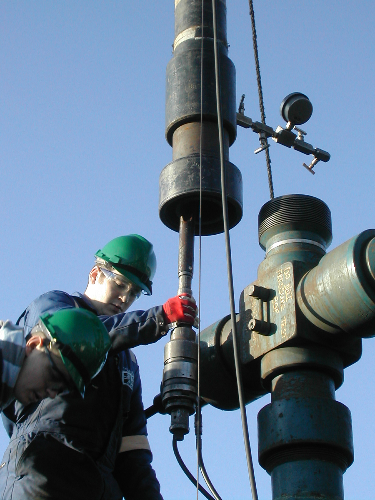
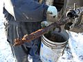
Well logging images
-

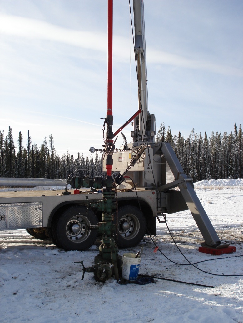
Wireline attached to top of Christmas Tree
-

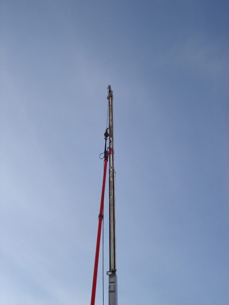
Oil Well Top of Wireline
-

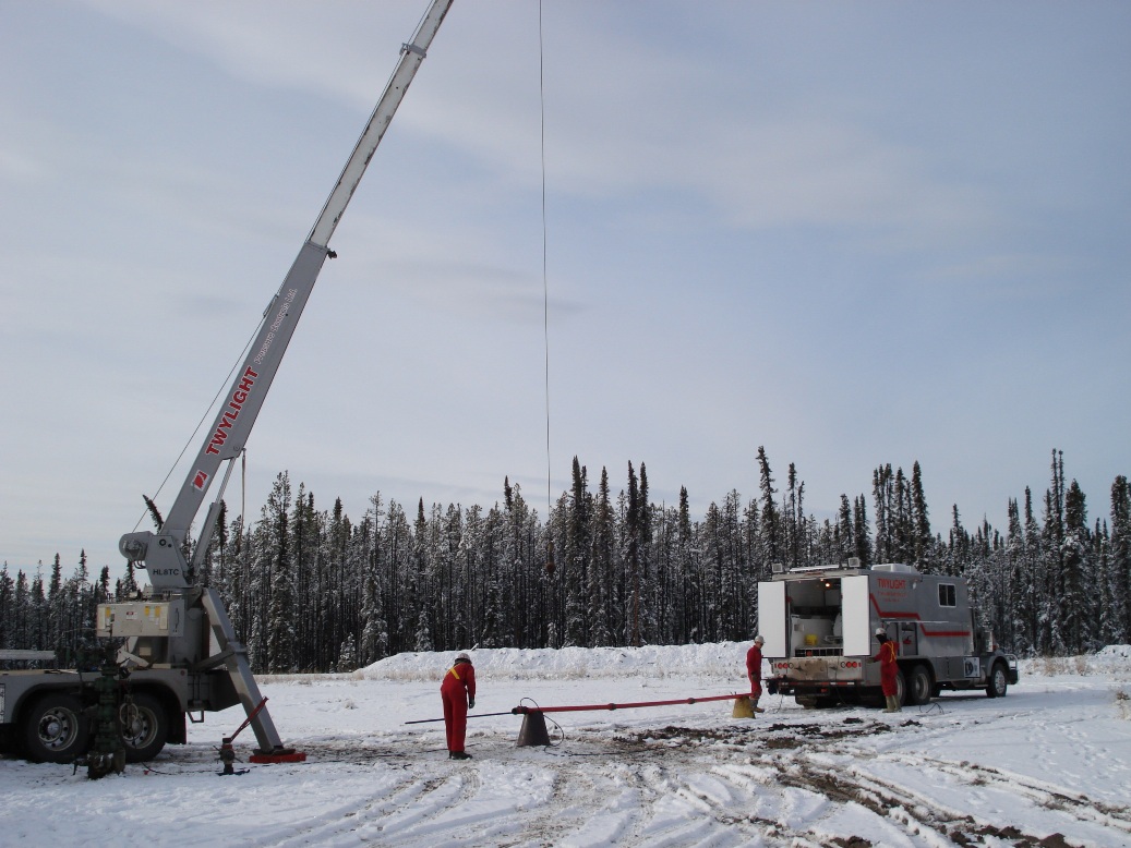
Wireline Truck with drum (inside)
-
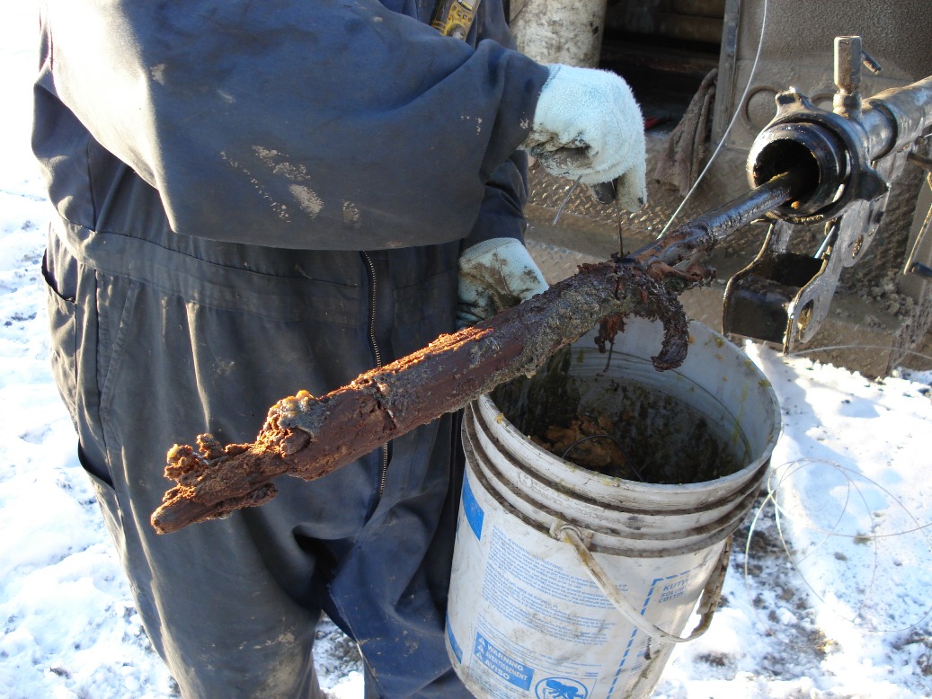
Wax being removed off a wireline wax knife
-

BO shifting tool
See also
- Drilling mud
- Drilling rig
- Formation evaluation
- Geosteering
- List of oilfield service companies
- Log ASCII Standard
- Wireline
References
- ^ Society of Professional Well Log Analysts (1975). Glossary of terms & expressions used in well logging. Houston, Texas: SPWLA. p. 74 p.. ISBN None.
- ^ Sengel, E.W. "Bill" (1981). Handbook on well logging. Oklahoma City, Oklahoma: Institute for Energy Development. p. 168 p.. ISBN 0-89419-112-8.
- ^ Hilchie, Douglas W. (1990). Wireline: A history of the well logging and perforating business in the oil fields. Boulder, Colorado: Privately Published. p. 200. ISBN None.
- ^ Pike, Bill; Rhonda Duey (2002). "Logging history rich with innovation" (– Scholar search). Hart's E&P: 52–55. http://www.accessmylibrary.com/coms2/summary_0286-7442038_ITM. Retrieved 2008-06-02.[dead link]
- ^ Now a division of Baker Hughes
- ^ Bourgoyne, Adam; Keith Millheim, Martin Chenevert, F.S. Young Jr. (1986). Applied Drilling Engineering. Richardson, TX: Society of Petroleum Engineers. p. 274 p.. ISBN 1-55563-001-4.
External links
Categories:- Well logging
- Petroleum production
- Economic geology
- Oil wells
- Geotechnical engineering
Wikimedia Foundation. 2010.
Look at other dictionaries:
well logging — karotažas statusas T sritis Standartizacija ir metrologija apibrėžtis Geofiziniai gręžinių tyrimo metodai, pagrįsti uolienų fizikinių savybių matavimais. atitikmenys: angl. logging services; well logging vok. Bohrlochaufnahme, f; Bohrlochmessung … Penkiakalbis aiškinamasis metrologijos terminų žodynas
well logging — the process or technique of recording a well log. * * * well logging, the making of exploratory test borings in an underground mineral formation, and maintaining a record or log of what is found … Useful english dictionary
well logging — the process or technique of recording a well log. * * * ▪ mining field technique used in mineral exploration to analyze the geologic formations penetrated by a drill hole. If the hole has been drilled by using coring techniques, the core… … Universalium
well logging — noun The analysis and recording of the strata penetrated by the drill of an oil well as an aid to exploration … Wiktionary
logging services — karotažas statusas T sritis Standartizacija ir metrologija apibrėžtis Geofiziniai gręžinių tyrimo metodai, pagrįsti uolienų fizikinių savybių matavimais. atitikmenys: angl. logging services; well logging vok. Bohrlochaufnahme, f; Bohrlochmessung … Penkiakalbis aiškinamasis metrologijos terminų žodynas
well log — noun : log I 3b(3) * * * log1 (def. 7). * * * well log, the log kept as a record of a well logging project … Useful english dictionary
Logging — is the process in which trees are cut down for forest management and timber. Use of the term logging in forestry In forestry the term logging is sometimes used in a narrow sense concerning the logistics of moving wood from the stump to somewhere… … Wikipedia
Logging while drilling — (LWD) is a technique of measuring geologic formation properties in real time while drilling an oil well.DescriptionLogging while drilling, along with measurement while drilling systems provide wellbore directional surveys, petrophysical well logs … Wikipedia
Density logging — Well logging Gamma ray logging Spontaneous potential logging Resistivity logging Density logging Sonic logging Caliper logging Mud logging LWD/MWD v · … Wikipedia
Well intervention — A well intervention, or well work , is any operation carried out on a oil or gas well during , or at the end of its productive life, that alters the state of the well and or well geometry, provides well diagnostics or manages the production of… … Wikipedia