- Steam turbine
-
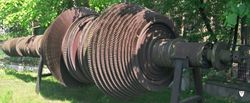
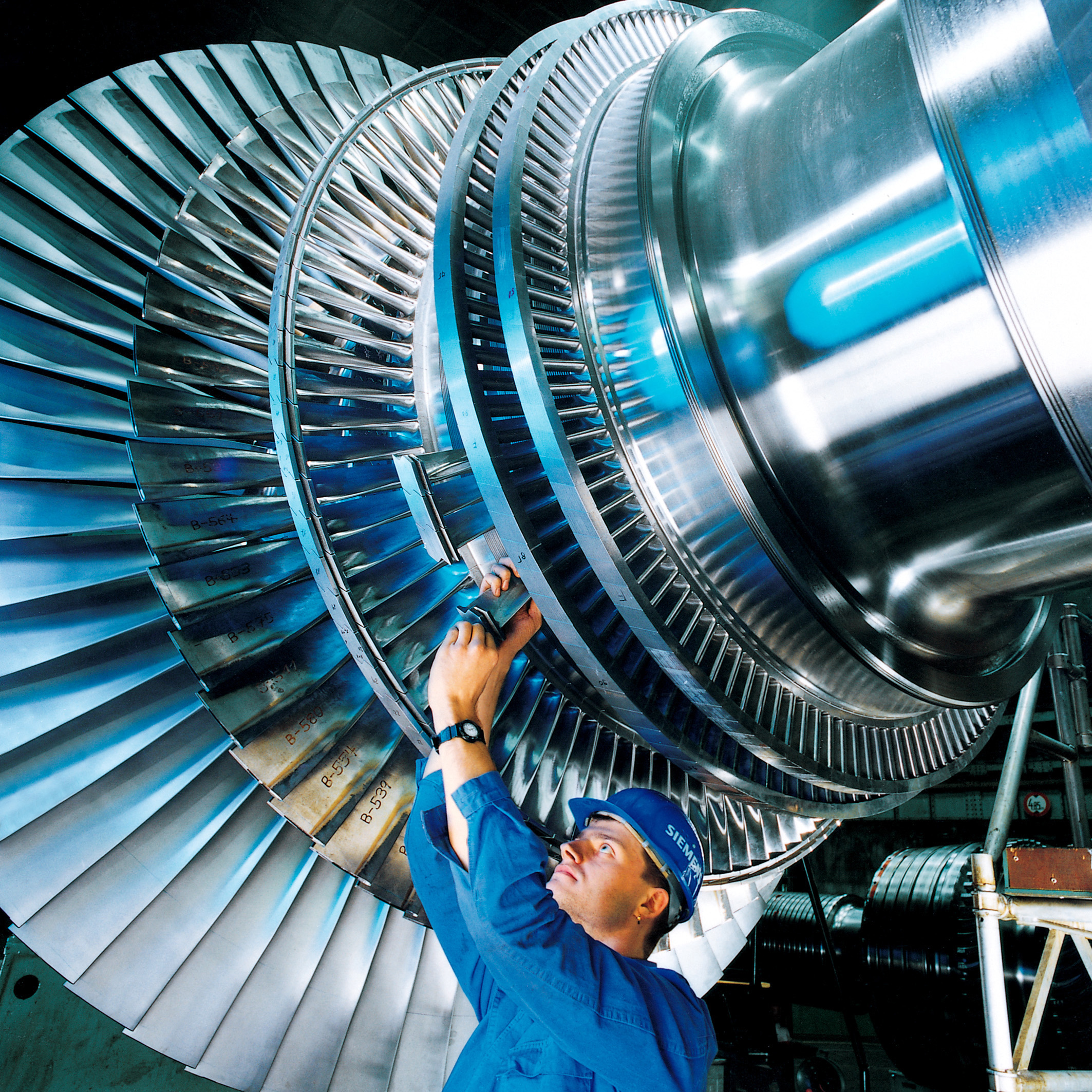
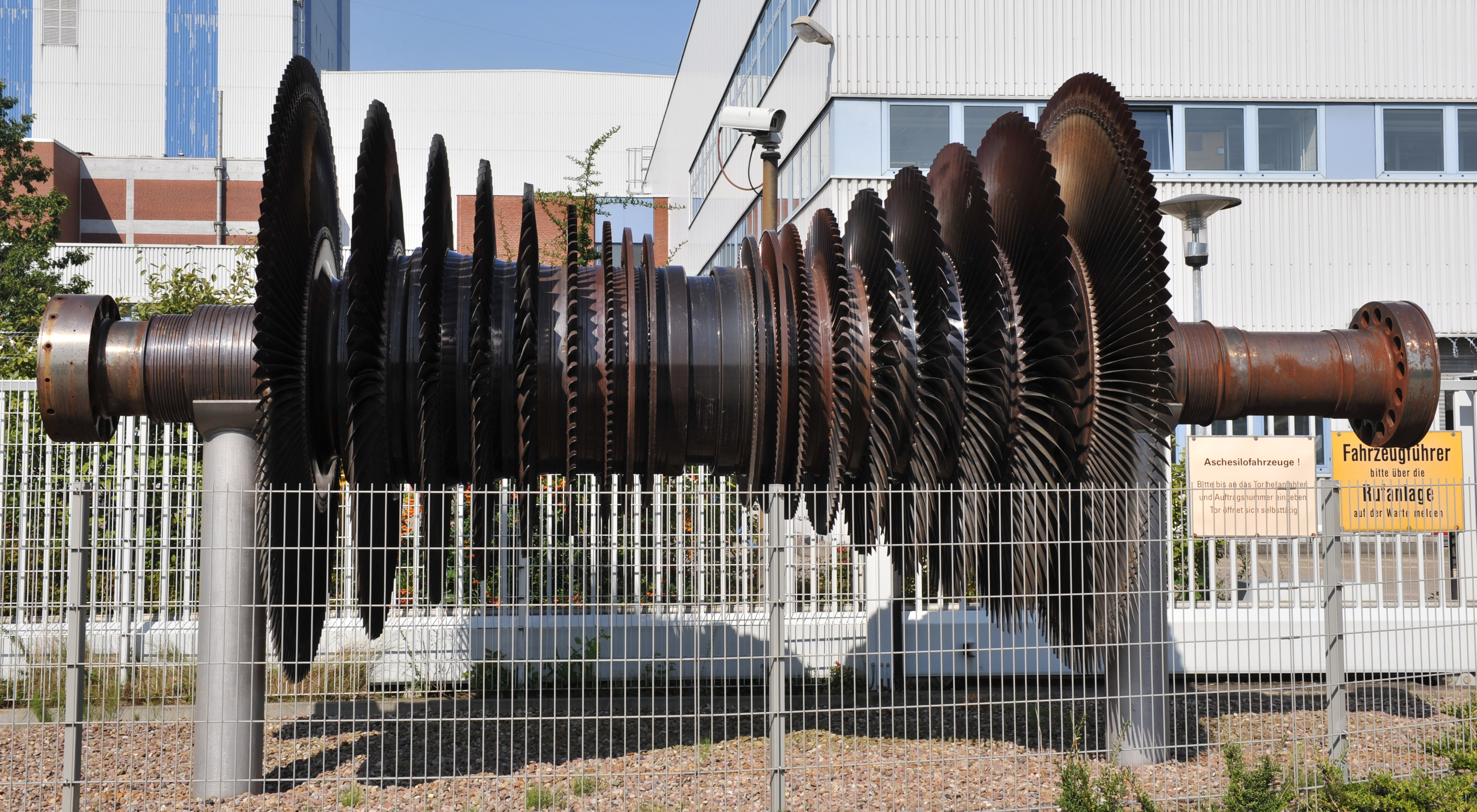
 A rotor of a modern steam turbine, used in a power plant
A steam turbine is a mechanical device that extracts thermal energy from pressurized steam, and converts it into rotary motion. Its modern manifestation was invented by Sir Charles Parsons in 1884.[1]
It has almost completely replaced the reciprocating piston steam engine primarily because of its greater thermal efficiency and higher power-to-weight ratio. Because the turbine generates rotary motion, it is particularly suited to be used to drive an electrical generator – about 90% of all electricity generation in the United States is by use of steam turbines.[2] The steam turbine is a form of heat engine that derives much of its improvement in thermodynamic efficiency through the use of multiple stages in the expansion of the steam, which results in a closer approach to the ideal reversible process.
Contents
History
 2000 KW Curtis steam turbine circa 1905.
The first device that may be classified as a reaction steam turbine was little more than a toy, the classic Aeolipile, described in the 1st century by Greek mathematician Hero of Alexandria in Roman Egypt.[3][4][5] More than a thousand years later, in 1543, Spanish naval officer Blasco de Garay used a primitive steam machine to move a ship in the port of Barcelona.[6] In 1551, Taqi al-Din in Ottoman Egypt described a steam turbine with the practical application of rotating a spit. Steam turbines were also described by the Italian Giovanni Branca (1629)[7] and John Wilkins in England (1648).[8] The devices described by al-Din and Wilkins are today known as steam jacks.
 Parsons turbine from the Polish destroyer ORP Wicher.
The modern steam turbine was invented in 1884 by the Anglo-Irish engineer Sir Charles Parsons, whose first model was connected to a dynamo that generated 7.5 kW (10 hp) of electricity.[9] The invention of Parson's steam turbine made cheap and plentiful electricity possible and revolutionised marine transport and naval warfare.[10] His patent was licensed and the turbine scaled-up shortly after by an American, George Westinghouse. The Parson's turbine also turned out to be easy to scale up. Parsons had the satisfaction of seeing his invention adopted for all major world power stations, and the size of generators had increased from his first 7.5 kW set up to units of 50,000 kW capacity. Within Parson's lifetime the generating capacity of a unit was scaled up by about 10,000 times,[11] and the total output from turbo-generators constructed by his firm C. A. Parsons and Company and by their licensees, for land purposes alone, had exceeded thirty million horse-power.[9]
A number of other variations of turbines have been developed that work effectively with steam. The de Laval turbine (invented by Gustaf de Laval) accelerated the steam to full speed before running it against a turbine blade. Hence the (impulse) turbine is simpler, less expensive and does not need to be pressure-proof. It can operate with any pressure of steam, but is considerably less efficient.
 Cut away of an AEG marine steam turbine circa 1905
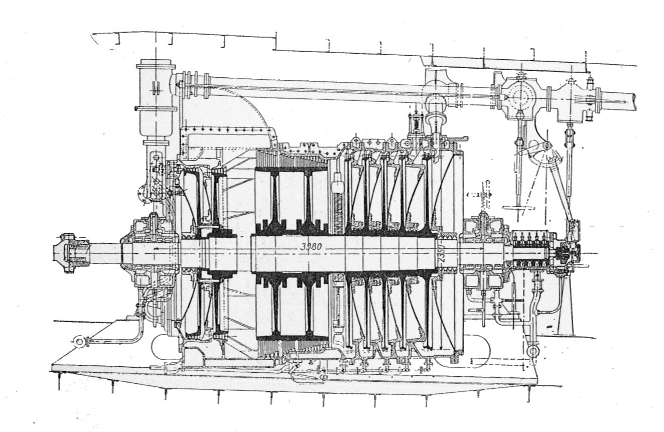
One of the founders of the modern theory of steam and gas turbines was also Aurel Stodola, a Slovak physicist and engineer and professor at Swiss Polytechnical Institute (now ETH) in Zurich. His mature work was Die Dampfturbinen und ihre Aussichten als Wärmekraftmaschinen (English The Steam Turbine and its perspective as a Heat Energy Machine) which was published in Berlin in 1903. In 1922, in Berlin, was published another important book Dampf und Gas-Turbinen (English Steam and Gas Turbines).
The Brown-Curtis turbine which had been originally developed and patented by the U.S. company International Curtis Marine Turbine Company was developed in the 1900s in conjunction with John Brown & Company. It was used in John Brown's merchant ships and warships, including liners and Royal Navy warships.
Types
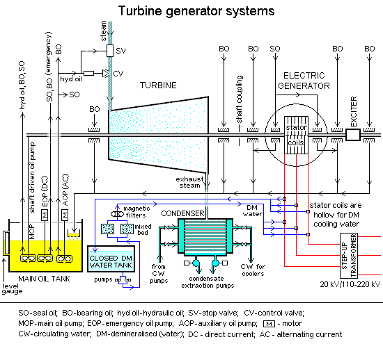
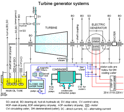 Schematic operation of a steam turbine generator system
Steam turbines are made in a variety of sizes ranging from small <1 hp (<0.75 kW) units (rare) used as mechanical drives for pumps, compressors and other shaft driven equipment, to 2,000,000 hp (1,500,000 kW) turbines used to generate electricity. There are several classifications for modern steam turbines.
Steam supply and exhaust conditions
These types include condensing, non condensing, reheat, extraction and induction.
Non condensing or back pressure turbines are most widely used for process steam applications. The exhaust pressure is controlled by a regulating valve to suit the needs of the process steam pressure. These are commonly found at refineries, district heating units, pulp and paper plants, and desalination facilities where large amounts of low pressure process steam are available.
Condensing turbines are most commonly found in electrical power plants. These turbines exhaust steam in a partially condensed state, typically of a quality near 90%, at a pressure well below atmospheric to a condenser.
Reheat turbines are also used almost exclusively in electrical power plants. In a reheat turbine, steam flow exits from a high pressure section of the turbine and is returned to the boiler where additional superheat is added. The steam then goes back into an intermediate pressure section of the turbine and continues its expansion.
Extracting type turbines are common in all applications. In an extracting type turbine, steam is released from various stages of the turbine, and used for industrial process needs or sent to boiler feedwater heaters to improve overall cycle efficiency. Extraction flows may be controlled with a valve, or left uncontrolled.
Induction turbines introduce low pressure steam at an intermediate stage to produce additional power.
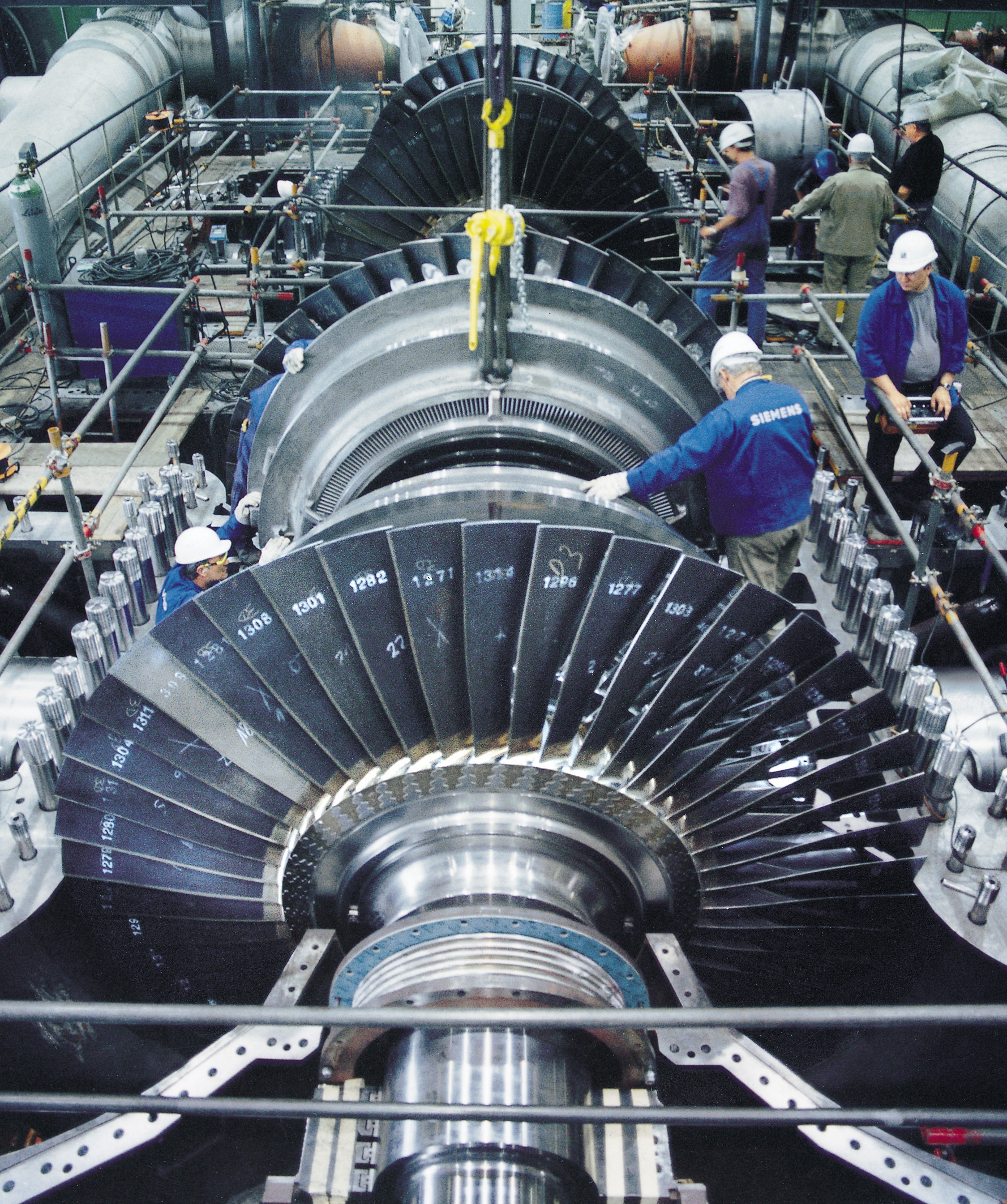
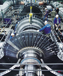 Mounting of a steam turbine produced by Siemens
Casing or shaft arrangements
These arrangements include single casing, tandem compound and cross compound turbines. Single casing units are the most basic style where a single casing and shaft are coupled to a generator. Tandem compound are used where two or more casings are directly coupled together to drive a single generator. A cross compound turbine arrangement features two or more shafts not in line driving two or more generators that often operate at different speeds. A cross compound turbine is typically used for many large applications.
Two-flow rotors
 A two-flow turbine rotor. The steam enters in the middle of the shaft, and exits at each end, balancing the axial force.
The moving steam imparts both a tangential and axial thrust on the turbine shaft, but the axial thrust in a simple turbine is unopposed. To maintain the correct rotor position and balancing, this force must be counteracted by an opposing force. Either thrust bearings can be used for the shaft bearings, or the rotor can be designed so that the steam enters in the middle of the shaft and exits at both ends. The blades in each half face opposite ways, so that the axial forces negate each other but the tangential forces act together. This design of rotor is called two-flow or double-exhaust. This arrangement is common in low-pressure casings of a compound turbine.[12]
Principle of operation and design
An ideal steam turbine is considered to be an isentropic process, or constant entropy process, in which the entropy of the steam entering the turbine is equal to the entropy of the steam leaving the turbine. No steam turbine is truly isentropic, however, with typical isentropic efficiencies ranging from 20–90% based on the application of the turbine. The interior of a turbine comprises several sets of blades, or buckets as they are more commonly referred to. One set of stationary blades is connected to the casing and one set of rotating blades is connected to the shaft. The sets intermesh with certain minimum clearances, with the size and configuration of sets varying to efficiently exploit the expansion of steam at each stage.
Turbine efficiency
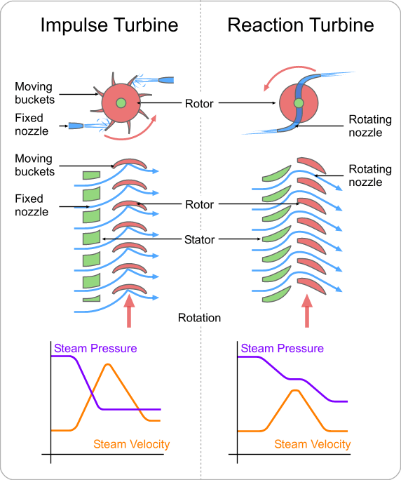
 Schematic diagram outlining the difference between an impulse and a reaction turbine
To maximize turbine efficiency the steam is expanded, doing work, in a number of stages. These stages are characterized by how the energy is extracted from them and are known as either impulse or reaction turbines. Most steam turbines use a mixture of the reaction and impulse designs: each stage behaves as either one or the other, but the overall turbine uses both. Typically, higher pressure sections are impulse type and lower pressure stages are reaction type.
Impulse turbines
An impulse turbine has fixed nozzles that orient the steam flow into high speed jets. These jets contain significant kinetic energy, which the rotor blades, shaped like buckets, convert into shaft rotation as the steam jet changes direction. A pressure drop occurs across only the stationary blades, with a net increase in steam velocity across the stage.
As the steam flows through the nozzle its pressure falls from inlet pressure to the exit pressure (atmospheric pressure, or more usually, the condenser vacuum). Due to this higher ratio of expansion of steam in the nozzle the steam leaves the nozzle with a very high velocity. The steam leaving the moving blades has a large portion of the maximum velocity of the steam when leaving the nozzle. The loss of energy due to this higher exit velocity is commonly called the carry over velocity or leaving loss.
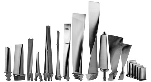
 A selection of turbine blades
Reaction turbines
In the reaction turbine, the rotor blades themselves are arranged to form convergent nozzles. This type of turbine makes use of the reaction force produced as the steam accelerates through the nozzles formed by the rotor. Steam is directed onto the rotor by the fixed vanes of the stator. It leaves the stator as a jet that fills the entire circumference of the rotor. The steam then changes direction and increases its speed relative to the speed of the blades. A pressure drop occurs across both the stator and the rotor, with steam accelerating through the stator and decelerating through the rotor, with no net change in steam velocity across the stage but with a decrease in both pressure and temperature, reflecting the work performed in the driving of the rotor.
Operation and maintenance
When warming up a steam turbine for use, the main steam stop valves (after the boiler) have a bypass line to allow superheated steam to slowly bypass the valve and proceed to heat up the lines in the system along with the steam turbine. Also, a turning gear is engaged when there is no steam to the turbine to slowly rotate the turbine to ensure even heating to prevent uneven expansion. After first rotating the turbine by the turning gear, allowing time for the rotor to assume a straight plane (no bowing), then the turning gear is disengaged and steam is admitted to the turbine, first to the astern blades then to the ahead blades slowly rotating the turbine at 10–15 RPM (0.17–0.25 Hz) to slowly warm the turbine.
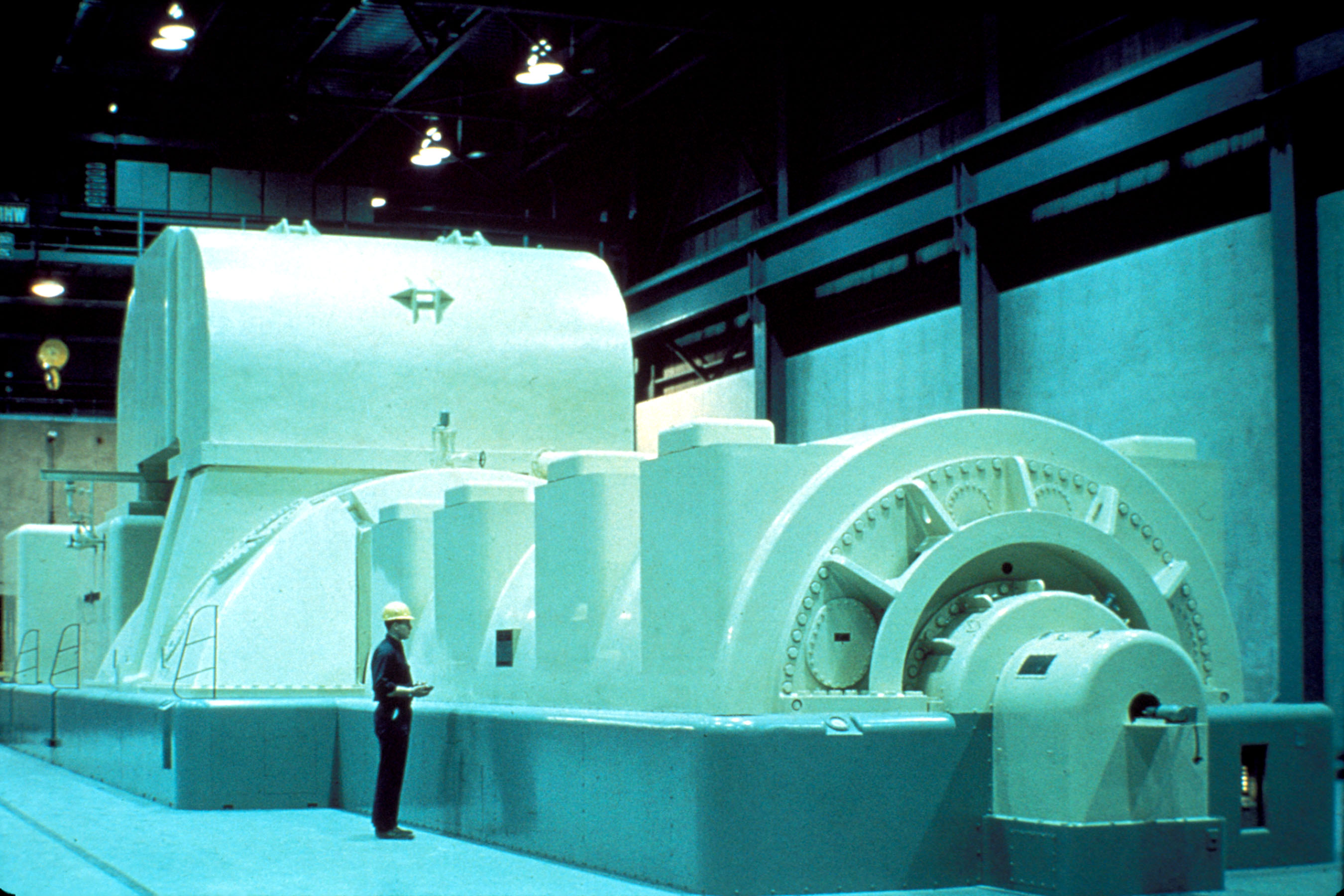
 A modern steam turbine generator installation
Any imbalance of the rotor can lead to vibration, which in extreme cases can lead to a blade breaking away from the rotor at high velocity and being ejected directly through the casing. To minimize risk it is essential that the turbine be very well balanced and turned with dry steam - that is, superheated steam with a minimal liquid water content. If water gets into the steam and is blasted onto the blades (moisture carry over), rapid impingement and erosion of the blades can occur leading to imbalance and catastrophic failure. Also, water entering the blades will result in the destruction of the thrust bearing for the turbine shaft. To prevent this, along with controls and baffles in the boilers to ensure high quality steam, condensate drains are installed in the steam piping leading to the turbine. Modern designs are sufficiently refined that problems with turbines are rare and maintenance requirements are relatively small.
Speed regulation
The control of a turbine with a governor is essential, as turbines need to be run up slowly, to prevent damage while some applications (such as the generation of alternating current electricity) require precise speed control.[13] Uncontrolled acceleration of the turbine rotor can lead to an overspeed trip, which causes the nozzle valves that control the flow of steam to the turbine to close. If this fails then the turbine may continue accelerating until it breaks apart, often spectacularly. Turbines are expensive to make, requiring precision manufacture and special quality materials.
During normal operation in synchronization with the electricity network, power plants are governed with a five percent droop speed control. This means the full load speed is 100% and the no-load speed is 105%. This is required for the stable operation of the network without hunting and drop-outs of power plants. Normally the changes in speed are minor. Adjustments in power output are made by slowly raising the droop curve by increasing the spring pressure on a centrifugal governor. Generally this is a basic system requirement for all power plants because the older and newer plants have to be compatible in response to the instantaneous changes in frequency without depending on outside communication.[14]
Thermodynamics of steam turbines
The steam turbine operates on basic principles of thermodynamics using the part of the Rankine cycle. Superheated vapor (or dry saturated vapor, depending on application) enters the turbine, after it having exited the boiler, at high temperature and high pressure. The high heat/pressure steam is converted into kinetic energy using a nozzle (a fixed nozzle in an impulse type turbine or the fixed blades in a reaction type turbine). Once the steam has exited the nozzle it is moving at high velocity and is sent to the blades of the turbine. A force is created on the blades due to the pressure of the vapor on the blades causing them to move. A generator or other such device can be placed on the shaft, and the energy that was in the vapor can now be stored and used. The gas exits the turbine as a saturated vapor (or liquid-vapor mix depending on application) at a lower temperature and pressure than it entered with and is sent to the condenser to be cooled.[15] If we look at the first law we can find an equation comparing the rate at which work is developed per unit mass. Assuming there is no heat transfer to the surrounding environment and that the change in kinetic and potential energy is negligible when compared to the change in specific entropy we come up with the following equation
where
- Ẇ is the rate at which work is developed per unit time
- ṁ is the rate of mass flow through the turbine
Isentropic turbine efficiency
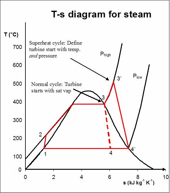
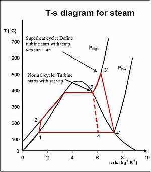 Rankine cycle with superheat
Process 1-2: The working fluid is pumped from low to high pressure.
Process 2-3: The high pressure liquid enters a boiler where it is heated at constant pressure by an external heat source to become a dry saturated vapor.
Process 3-3': The vapour is superheated.
Process 3-4 and 3'-4': The dry saturated vapor expands through a turbine, generating power. This decreases the temperature and pressure of the vapor, and some condensation may occur.
Process 4-1: The wet vapor then enters a condenser where it is condensed at a constant pressure to become a saturated liquid.To measure how well a turbine is performing we can look at the isentropic efficiency. This compares the actual performance of a device and the performance that would be achieved under idealized circumstances.[16] When calculating the isentropic efficiency, heat to the surroundings is assumed to be zero. The starting pressure and temperature is the same for both the isentropic and actual efficiency. Since state 1 is the same for both efficiencies, the specific enthalpy h1 is known.[16] At turbine exit, the specific entropy for the actual process is greater than the specific entropy for the isentropic process due to irreversibility in the actual process. The specific entropy is evaluated at the same pressure for the actual and isentropic processes in order to give a good comparison between the two.
The isentropic efficiency is found by dividing the actual work by the maximum work that could be achieved if there were no irreversibility in the process.[16]
where
- h1 is the specific enthalpy at state one
- h2 is the specific enthalpy at state two for an actual process
- h2s is the specific enthalpy at state two for an isentropic process
Calculating turbine efficiency
The efficiency of the steam turbine can be calculated by using the Kelvin statement of the Second law of Thermodynamics.[16]
where
- Wcycle is the Work done during one cycle
- QH is the Heat transfer received from the heat source
If we look at the Carnot cycle the maximum efficiency of a steam turbine can be calculated. This efficiency can never be achieved in the real world due to irreversibility during the process, but it does give a good measure as to how a particular turbine is performing.[16]
where
- TL is the absolute temperature of the vapor moving out of the turbine
- TH is the absolute temperature of the vapor coming from the boiler
Direct drive
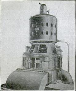
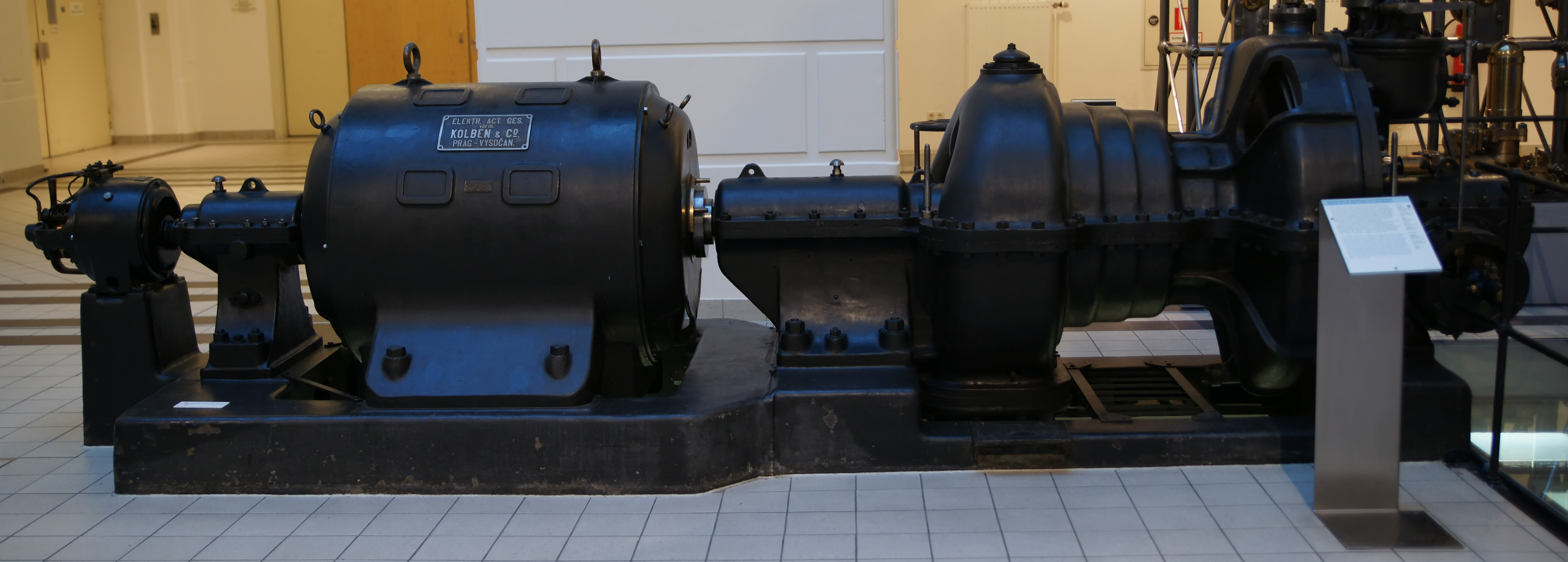
 A small industrial steam turbine (right) directly linked to a generator (left). This turbine generator set of 1910 produced 250 kW of electrical power.
Electrical power stations use large steam turbines driving electric generators to produce most (about 80%) of the world's electricity. The advent of large steam turbines made central-station electricity generation practical, since reciprocating steam engines of large rating became very bulky, and operated at slow speeds. Most central stations are fossil fuel power plants and nuclear power plants; some installations use geothermal steam, or use concentrated solar power (CSP) to create the steam. Steam turbines can also be used directly to drive large centrifugal pumps, such as feedwater pumps at a thermal power plant.
The turbines used for electric power generation are most often directly coupled to their generators. As the generators must rotate at constant synchronous speeds according to the frequency of the electric power system, the most common speeds are 3,000 RPM for 50 Hz systems, and 3,600 RPM for 60 Hz systems. Since nuclear reactors have lower temperature limits than fossil-fired plants, with lower steam quality, the turbine generator sets may be arranged to operate at half these speeds, but with four-pole generators, to reduce erosion of turbine blades.[17]
Marine propulsion
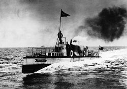 The Turbinia, 1894, the first steam turbine-powered ship
In ships, compelling advantages of steam turbines over reciprocating engines are smaller size, lower maintenance, lighter weight, and lower vibration. A steam turbine is only efficient when operating in the thousands of RPM, while the most effective propeller designs are for speeds less than 100 RPM; consequently, precise (thus expensive) reduction gears are usually required, although several ships, such as Turbinia, had direct drive from the steam turbine to the propeller shafts. Another alternative is turbo-electric drive, where an electrical generator run by the high-speed turbine is used to run one or more slow-speed electric motors connected to the propeller shafts; precision gear cutting may be a production bottleneck during wartime. The purchase cost is offset by much lower fuel and maintenance requirements and the small size of a turbine when compared to a reciprocating engine having an equivalent power. However, diesel engines are capable of higher efficiencies: propulsion steam turbine cycle efficiencies have yet to break 50%, yet diesel engines routinely exceed 50%, especially in marine applications.[18][19][20]
Nuclear-powered ships and submarines use a nuclear reactor to create steam. Nuclear power is often chosen where diesel power would be impractical (as in submarine applications) or the logistics of refuelling pose significant problems (for example, icebreakers). It has been estimated that the reactor fuel for the Royal Navy's Vanguard class submarine is sufficient to last 40 circumnavigations of the globe – potentially sufficient for the vessel's entire service life. Nuclear propulsion has only been applied to a very few commercial vessels due to the expense of maintenance and the regulatory controls required on nuclear fuel cycles.
Locomotives
Main article: Steam turbine locomotiveA steam turbine locomotive engine is a steam locomotive driven by a steam turbine.
The main advantages of a steam turbine locomotive are better rotational balance and reduced hammer blow on the track. However, a disadvantage is less flexible power output power so that turbine locomotives were best suited for long-haul operations at a constant output power.[21]
The first steam turbine rail locomotive was built in 1908 for the Officine Meccaniche Miani Silvestri Grodona Comi, Milan, Italy. In 1924 Krupp built the steam turbine locomotive T18 001, operational in 1929, for Deutsche Reichsbahn.
See also
References
- ^ Encyclopædia Britannica (1931-02-11). "Sir Charles Algernon Parsons (British engineer) - Britannica Online Encyclopedia". Britannica.com. http://www.britannica.com/EBchecked/topic/444719/Sir-Charles-Algernon-Parsons. Retrieved 2010-09-12.
- ^ Wiser, Wendell H. (2000). Energy resources: occurrence, production, conversion, use. Birkhäuser. p. 190. ISBN 9780387987446. http://books.google.com/books?id=UmMx9ixu90kC&pg=PA190&dq=electrical+power+generators+steam+percent&hl=en&ei=JppoTpVexNmBB4C72MkM&sa=X&oi=book_result&ct=result&resnum=2&ved=0CDgQ6AEwATgK#v=onepage&q=steam&f=false.
- ^ turbine. Encyclopedia Britannica Online
- ^ A new look at Heron's 'steam engine'" (1992-06-25). Archive for History of Exact Sciences 44 (2): 107-124.
- ^ O'Connor, J. J.; E. E. Roberston (1999). Heron of Alexandria. MacTutor
- ^ Blasco de Garay's 1543 Steamship, Rochester History Resources, University of Rochester, 1996, http://www.history.rochester.edu/steam/garay/. Retrieved 2008-04-24.
- ^ "Power plant engineering". P. K. Nag (2002). Tata McGraw-Hill. p.432. ISBN 978-0-07-043599-5
- ^ Taqi al-Din and the First Steam Turbine, 1551 A.D., web page, accessed on line October 23, 2009; this web page refers to Ahmad Y Hassan (1976), Taqi al-Din and Arabic Mechanical Engineering, pp. 34-5, Institute for the History of Arabic Science, University of Aleppo.
- ^ a b [1][dead link]
- ^ [2][dead link]
- ^ Parsons, Sir Charles A.. "The Steam Turbine". http://www.history.rochester.edu/steam/parsons/part1.html.
- ^ "Steam Turbines (Course No. M-3006)". PhD Engineer. http://www.pdhengineer.com/Course%20Files/Completed%20Course%20PDF%20Files/Mechanical/Steam%20Turbines.pdf. Retrieved 2011-09-22.
- ^ Whitaker, Jerry C. (2006). AC power systems handbook. Boca Raton, FL: Taylor and Francis. p. 35. ISBN 978-0-8493-4034-5.
- ^ Speed Droop and Power Generation. Application Note 01302. 2. Woodward. Speed
- ^ Roymech, http://www.roymech.co.uk/Related/Thermos/Thermos_Steam_Turbine.html
- ^ a b c d e "Fundamentals of Engineering Thermodynamics" Moran and Shariro, Published by Wiley
- ^ Leyzerovich, Alexander (2005). Wet-steam Turbines for Nuclear Power Plants. Tulsa OK: PennWell Books. p. 111. ISBN 978-1-59370-032-4.
- ^ "MCC CFXUpdate23 LO A/W.qxd" (PDF). http://ansys.com/assets/testimonials/siemens.pdf. Retrieved 2010-09-12.
- ^ "New Benchmarks for Steam Turbine Efficiency - Power Engineering". Pepei.pennnet.com. Archived from the original on 2010-11-18. http://pepei.pennnet.com/display_article/152601/6/ARTCL/none/none/1/New-Benchmarks-for-Steam-Turbine-Efficiency/. Retrieved 2010-09-12.
- ^ https://www.mhi.co.jp/technology/review/pdf/e451/e451021.pdf
- ^ Streeter, Tony: 'Testing the Limit' (Steam Railway Magazine: 2007, 336), pp. 85
Further reading
- Cotton, K.C. (1998). Evaluating and Improving Steam Turbine Performance.
- Parsons, Charles A. (1911). The Steam Turbine. University Press, Cambridge.
- Traupel, W. (1977) (in German). Thermische Turbomaschinen.
- Thurston, R. H. (1878). A History of the Growth of the Steam Engine. D. Appleton and Co..
External links
- Steam Turbines: A Book of Instruction for the Adjustment and Operation of the Principal Types of this Class of Prime Movers by Hubert E. Collins
- Tutorial: "Superheated Steam"
- Flow Phenomenon in Steam Turbine Disk-Stator Cavities Channeled by Balance Holes
- Extreme Steam- Unusual Variations on The Steam Locomotive
- Interactive Simulation of 350MW Steam Turbine with Boiler developed by The University of Queensland, in Brisbane Australia
- "Super-Steam...An Amazing Story of Achievement" Popular Mechanics, August 1937
Heat engines Carnot engine · Fluidyne · Gas turbine · Hot air · Jet · Photo-Carnot engine · Piston · Pistonless (Rotary) · Rijke tube · Rocket · Split-single · Steam (reciprocating) · Steam turbine · Stirling · ThermoacousticThermodynamic cycle Categories:- Turbines
- Steam engines
- English inventions
- History of the steam engine
- Steam turbines


Wikimedia Foundation. 2010.