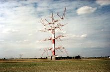
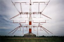
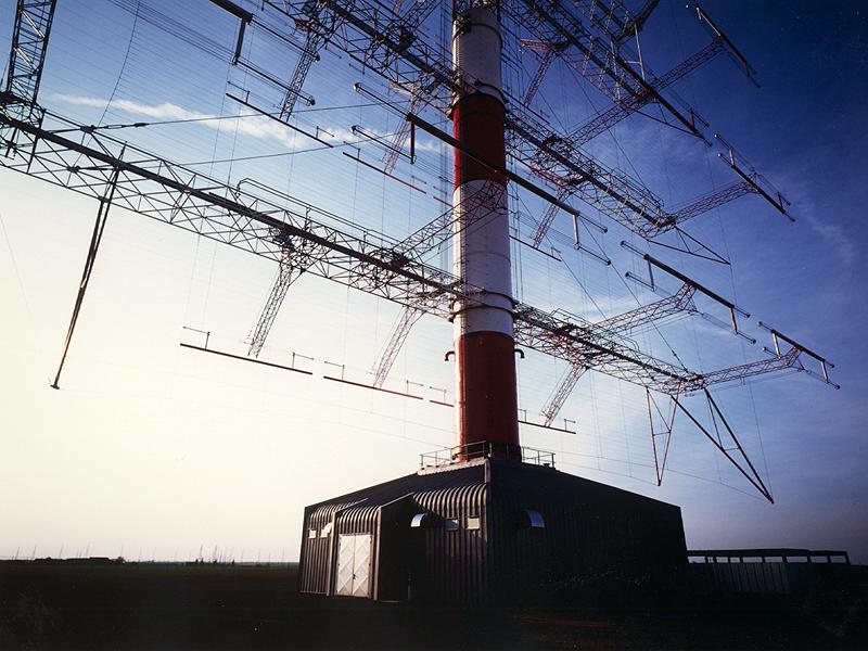
- HRS antenna
-
HRS type antennas are more or less the standard antenna used for long distance high power shortwave broadcasting (> 1000 km).
History of HRS design
HRS antennas were invented during the 1920s and 1930s when there was a lot of experimentation with long distance shortwave broadcasting. Before HRS antennas became the default design for high power broadcasting in the 1950s, there were Sterba curtains.
Sterba curtains are modest-gain single-band curtain array antennas. They are named after EJ Sterba, who developed a simple shortwave curtain array for Bell Labs in the 1930's. Sterba curtain arrays are described in William Orr's Radio Handbook.
There are multiple feed arrangements for the Sterba curtain arrays, as with HRS type antennas. However, Sterba arrays provide a very limited gain-bandwidth system for the demands of modern shortwave broadcasting systems.
Sterba curtan arrays proceed HRS type antennas by less than a decade. Only about 1% of high power HF broadcasting antennas in use in the 2000s are Sterba type curtain arrays. Many of these Sterba arrays may be indicated in HRS notation as there is no separate Sterba type notation for curtain arrays. It is expected that by 2020 that all Sterba type curtain arrays will be decommissioned.
More often than not Distributed or Branch Feed curtains are used, not Sterba arrays. The Distributed or Branch Feed curtains are considered to be classical HRS type antennas. There are 4 mathematical model types of ITU HRS type HF antennas, so these non-Sterba feed designs do indeed offer greater flexibility for transmission system designers.
Distributed or Branch Feed curtain arrays are called HR type curtain arrays. The H and R standing for Height and Rows. When they are steerable, they are sometimes called HRS arrays, the S representing "steerable".
An HR 4/3 would be an antenna 4 elements high and 3 elements wide. If it was an HRS 4/3, it would be a steerable array of the same element configuration.
The HRS antenna type was not originally intended for voice and music broadcasting. However, the directional properties of this antenna type were ideal for voice broadcasting—and the design is now pervasive in international broadcasting by the 1950s. As far back as the mid-1930s, Radio Netherlands was using a rotatable HRS antenna for global coverage.
Nomenclature
The HR is arbitrary, but may have originated from Horizontal Radiator. The S just means "Slewable", which means that the antenna beam can be directed up to (-/+) 25 degrees horizontally. S can also refer to this antenna type's limited vertical slewability as well. The complete name for this antenna type should be HRRS type antennas, but the extra R for Reversible is seldom used. RCI Sackville may have 2 HRRS type antennas—perhaps the only ones in North America.
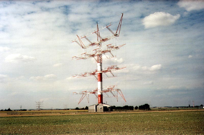
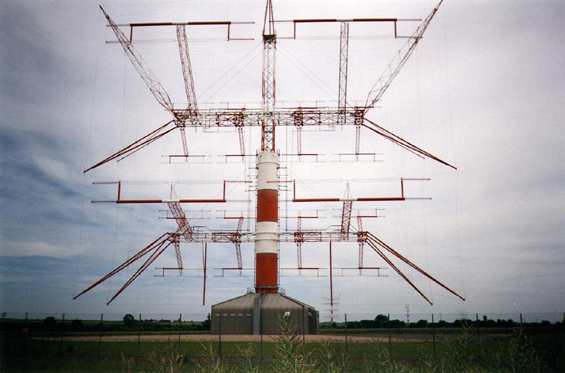
 Example of a theoretical HRS Shortwave relay station
A versatile antenna type
Important technical variations in HRS antennas
- HRS type antennas come in two types, fixed azimuth and rotatable.
- About 80% of all commissioned HRS type antennas in use today are fixed azimuth.
- Electrical slewing allows a fixed azimuth HRS antenna beam to be moved by as much as 25 degrees, however most designs only allow for 15 degrees.
- Only one type of HRS rotatable antenna is coupled with a building that houses a transmitter—the ALLISS system.
What are HRS type antennas?
The curtain antenna is a dipole array, consisting of rows and columns of dipoles.
- The curtain antenna is a high gain directional antenna, that is designed for medium and long range shortwave communications.
- The HR(S) notation is as follows
- HR Rows/Columns/Wavelength(s) -- Above Ground
How to interpret HRS notation
An HR 4/4/1 antenna has the following characteristics
- 4 rows
- 4 columns
- is 1 wavelength Above Ground (with respect to mid-band transmission frequency)
Syntax note: HRS
- The S means is that the antenna's pattern is electrically steerable.
- Electrical steering is typically done in the horizontal orientation, with some adjustments being possible in the vertical domain.
- Electrical steering of the antenna beam typically is limited to (-/+) 15° in the vertical, and about 5° in the horizontal.
Notes on HRS notation
HRS transmission systems can be "double sided", but in this case HRRS notation is used. The extra R meaning "Reversible". Very few HRRS antenna systems are in use worldwide.
- HRS antennas of type HRS 1/1/1 are undefined.
- HRS antennas of type HRS 1/2/1 and 2/1/1 exist, but see little practical use in broadcasting.
- The number of rows can be 2, 3, 4, 6, 8 or 12.
- The number of columns is usually 2, 3, 4, 6 or 8.
- The dipoles are ALWAYS horizontally polarized.
- A reflector screen is placed behind the dipole array so as to provide a directive beam.
- The Russian Woodpecker Over The Horizon Radar may have used an antenna of type HRS 32/16/0.75 (not verified, estimated), with potential directivity in the gigawatt range.
Azimuth beamwidth
- For a 2-wide dipole array, the beamwidth is around 50°
- For a 3-wide dipole array, the beamwidth is around 40°
- For a 4-wide dipole array, the beamwidth is around 30°
The main beam can be slewed by 15° or 30° so that a maximum coverage of 90° can be achieved.
Vertical Launch Angle
The number of dipole rows and the height of the lowest element above ground determine the elevation angle and consequently the distance to the service area.
- A 2-row high array has a typical takeoff angle of 20°
- is most commonly used for medium range communications.
- A 4-row high array has a typical takeoff angle of 10°
- is most commonly used for long range communications.
- A 6-row array is similar to a 4-row, but can achieve 5° to 10° takeoff angles. This antenna type can be used in shortwave communications circuits of 12000 km, and is highly directive.
Note that it is possible for details of the antenna site to wreak havoc with the designers plans such that takeoff angle and matching may be adversely affected. One amusing incident had the designers struggling to match a new antenna for six weeks. As an identical antenna had worked perfectly at another site they were stumped. Skelton's Aerials SME had to show the designers how to match it and the problem was quickly solved. Sloping ground was to blame.
In the good old days Skelton Transmitting Station had "Ionospheric Sounding Equipment". This comprised a small WW2 radar transmitter (retuned) that could fire 16KW pulses into an HRRS 8 array. There was a transmit-receive switch using thermionic valves. This fed the received signal into a Racal RA17 receiver. The output of the Racal drove a cathode ray tube with a graticule calibrated in distance. One would see "grass" from ground returns out to about 50 miles then it would flatline until the first and second hops were seen. If one was getting a return echo from the correct distance it was a certainty that the signal was reaching its desired location. The equipment blurb described the apparatus as being "Highly useful for assessing reception conditions in a country where it is not convenient to be". Unfortunately the equipment was commandeered by Tatsfield Receiving Station in the 1960s, however without the proper HRRS8 aerial arrays the results would have probably been very poor indeed. (if the antenna gain is halved the return signal reduces to a quarter - this a fundamental truth with radar)
Variations of HRS antennas
Curtain antennas are available in two sizes.
- A low band array typically covers the 6, 7, 9 and 11 MHz bands.
- Low band antennas are typically larger and taller.
- A high band array typically covers the 11, 13, 15, 17 and 21 MHz bands (or 13-26 MHz bands).
- High band antennas are typically smaller and shorter.
Transmission system optimization for geopolitics
- Occasionally international broadcasters may use — for reasons of geopolitical necessity — highband and midband as well as lowband HRS curtain arrays.
- Using 3 HR curtain arrays to cover the HF broadcasting spectrum creates a highly optimized HF transmission system.
Cost issues
- HF transmission systems using 3 or more curtain arrays can be costly to build and maintain.
- Since the mid 1990s no new HF relay stations have been built.
- Existing HRS shortwave transmission systems (built before 1992) will likely remain in use for many years. The modern HRS antenna design thankfully has a long lifespan.
 ALLISS antenna as viewed underneath
Examples of HRS antennas
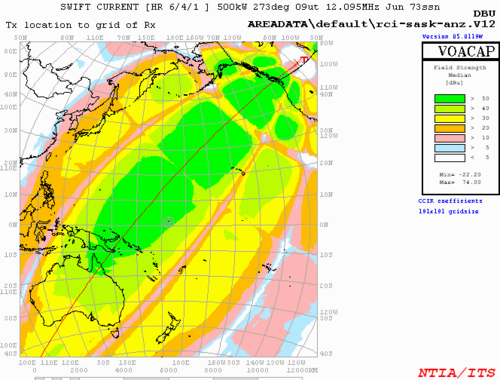
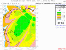
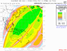
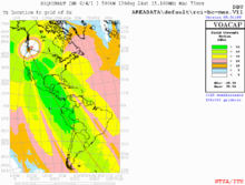
This is an example of theoretical HRS design shortwave relay stations. This may help one better understand HRS antenna directivity.
-
Targeting Australasia
-
Targeting Indonesia
-
Targeting Latin America
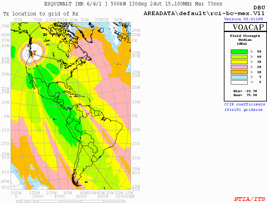
A proposal for a Radio Canada International relay station to be constructed in Tofino-Ucluelet found at http://cbc.am/rci-bc.htm
- RFI at Issoudun
-
Volga ALLISS Module
-
Ganges ALLISS Module
-

Former RFI Issoudun Relay station feeders and curtain arrays
-

Former RFI Issoudun Relay curtain arrays
The International broadcasting center of TDF (Télédiffusion de France) is at Issoudun/Ste Aoustrille. Issoudun is currently utilized by TDF for shortwave transmissions. The site uses 12 rotary ALLISS antennas fed by 12 transmitters of 500 kW each to transmit shortwave broadcasts by Radio France International (RFI), along with other broadcast services.
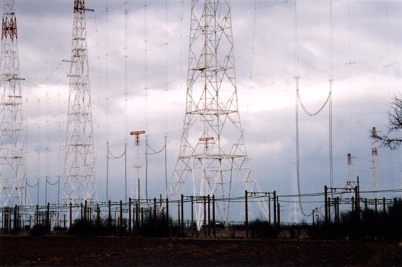
Shortwave relay stations using only HRS antennas
This is an incomplete list of stations using only HRS antennas, sorted by country name.
Active sites
- Radio Canada International Sackville, NB
- RNZI Rangataki Plains
UK
- BBCWS Ascension Island
- BBCWS Rampisham
- BBCWS Skelton
- BBCWS Woofferton
Decommissioned sites
- CVC International, Darwin, NT at Cox Peninsula. It was formerly a Radio Australia relay station. As the land has been turned over to aboriginal land owners in 2008 by a court decision, the site was dismantled in 2009. It is not currently known if there are any remaining HRS antenna towers.
Spain
- Playa de Pals Radio Station Museum (the HRS antenna field is now a 12 hole golf course)
USA
- VOA Delano, California Relay Station (mothball status, could be reactivated in some emergency situations)
- VOA Greenville-A Relay Station (mothball status, could be reactivated in some emergency situations) -- not all antennas are HRS type.
External links
ALLISS Technology portals
Analog and digital audio broadcasting TerrestrialRadio modulation Frequency allocations Digital systems SatelliteFrequency allocations Digital systems Commercial radio providers Subcarrier signalsRelated topicsTechnical (Audio): Audio processing · Audio data compression
Technical (AM Stereo formats): Belar · C-QUAM · Harris · Magnavox · Kahn-Hazeltine
Technical (Emission): Digital radio · Error correction · Multipath propagation · SW Relay Station · AM radio · AM broadcasting · Extended AM broadcast band · FM radio · FM broadcasting · FM broadcast band · Cable radio
Cultural: History of radio · International broadcasting
Comparison of radio systemsAntenna types Isotropic Omnidirectional Coaxial antenna · Dipole antenna · Discone antenna · Folded unipole antenna · Ground-plane antenna · Helical antenna · J-pole antenna · Mast radiator · Monopole antenna · Random wire antenna · Rubber Ducky antenna · T2FD Antenna · Whip antennaDirectional AWX antenna · Beverage antenna · Cantenna · Collinear antenna · Fractal antenna · Ground dipole · Helical antenna · Horizontal curtain · Horn · Inverted vee antenna · Log-periodic antenna · Loop antenna · Microstrip antenna · Patch antenna · Phased array · Parabolic antenna · Plasma antenna · Quad antenna · Reflective array antenna · Regenerative loop antenna · Rhombic antenna · Sector antenna · Short backfire antenna · Slot antenna · Turnstile antenna · Vivaldi-antenna · Yagi-Uda antennaApplication-specific Categories:- Radio frequency antenna types
- Radio frequency propagation


Wikimedia Foundation. 2010.