- Rubber Ducky antenna
-
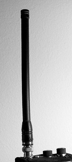
The Rubber Ducky antenna (or Rubber Duck aerial) is an electrically short monopole antenna which functions somewhat like a base-loaded whip antenna and is sealed in a rubber or plastic jacket to protect the antenna.[1] Electrically short antennas are often used in portable equipment because a one-quarter wavelength element, necessary for resonance of a linear element over a ground-plane, is often too long for convenient portable operation. Many years after its invention in 1958, the Rubber Ducky antenna became the antenna of choice for many portable radio devices, including walkie-talkies and other portable transceivers, scanners, GPS receivers, and any other device where safety and robustness take precedence over antenna capabilities.
Contents
Origin of the name
Two rumors link the naming of the antenna with the Kennedy family.[1] In the early 60s the Rubber Ducky became the antenna of choice for personal walkie-talkie transceivers used by police and security services, including the U.S. Secret Service, which guards the President of the United States. According to one rumor, the young Caroline Kennedy, daughter of President John F. Kennedy, named the flexible device when she pointed at one on an agent's transceiver and said, "rubber ducky". On the other hand Dr. Thomas A. Clark, a senior scientist with NASA, claims to have named it after listening to one of Vaughn Meeder's comedies about the Kennedy family.
Description
Before the Rubber Ducky, antennas on portable radios usually consisted of quarter-wave whip antennas, rods whose length was one-quarter of the wavelength of the radio waves used.[1] In the VHF range where they were used, these antennas were 2 or 3 feet long, making them cumbersome. They were often made of telescoping tubes that could be retracted when not in use. To eliminate the need for retraction, electrically short antennas, shorter than one-quarter wavelength, began to be used. Electrically short antennas have considerable capacitive reactance, so to make them resonant at the operating frequency an inductor (loading coil) is added in series with the antenna. Antennas which have these inductors built into their bases are called base-loaded whips.
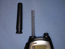
The Rubber Ducky is an electrically short quarter-wave antenna in which the inductor, instead of being in the base, is built into the antenna itself. The antenna is made of a narrow helix of wire like a spring, which functions as the needed inductor. The springy wire is flexible, making it less prone to damage than a stiff antenna. The spring antenna is further enclosed in a plastic or rubber-like covering to prevent it from catching on things. The technical name for this type of antenna is a normal-mode helix.[2] Rubber Ducky antennas are typically 4% to 15% of a wavelength long.[2]
 Protective rubber removed from the antenna on a UHF CB transceiver. The entire length used for base loading.
Effective aperture
Because the length of this antenna is significantly smaller than a wavelength the effective aperture is approximately:[3]
Although like other electrically short antennas the Rubber Ducky has poorer performance (less gain) than a quarter-wave whip, it has somewhat better performance than an equal length base loaded antenna. This is because since the inductance is distributed throughout the antenna it allows somewhat greater current in the antenna.
Performance
If care is taken in its design to produce a reasonably high radiation resistance, one can produce a useful antenna. Rubber Ducky antennas have reasonable performance, but they do not have either the gain or the aperture of larger antennas. Therefore, their performance will always be somewhat compromised. They are difficult to characterize electrically because the current distribution along the element is not sinusoidal as is the case of a thin linear array.
Design rules
- If the coils of the spring are wide (a large diameter), relative to the length of the array, the resulting antenna will have narrow bandwidth.
- Conversely, if the coils of the spring are narrow, relative to the length of the array, the resulting antenna will have its largest possible bandwidth.
- If the antenna is resonant, and the spring has a large diameter, the impedance will be well below 50 ohms, tending towards zero ohms with large inductors as the structure starts to resemble a series-tuned circuit with little radiation resistance.
- If the antenna is resonant, and the spring has a small diameter, the impedance will increase towards 70 ohms.
From these rules, one can surmise that it is possible to design a Rubber Ducky antenna that has about 50 ohms impedance at its feed-point but a compromise of bandwidth may be necessary. Modern Rubber Ducky antennas such as those used on cell phones are tapered in such a way that few performance compromises are necessary.
Variations
Some Rubber Ducky antennas are designed quite differently than the original design. One type uses a spring only for support. The spring is electrically shorted out. The antenna is therefore electrically, a linear element antenna. Some other Rubber Ducky antennas use a spring of non-conducting material for support and comprise a collinear array antenna. Such antennas are still called Rubber Ducky antennas even though they function quite differently (and often better) than the original spring antenna. The Rubber Ducky antenna has recently become known as the Flagelliform antenna as well.
See also
- isotropic antenna
- omnidirectional antenna
- whip antenna
- driven element
- balun
- amateur radio
- shortwave listening
References
- ^ a b c Johnson, Richard B. (2006). "Rubbber Ducky Antenna". Abominable Firebug. Richard Johnson's personal website. http://www.abominablefirebug.com/RDuckey.html. Retrieved 2011-04-06.. A note at the bottom of the page says this page is not copyrighted, and text from this page has been quoted verbatim in this article
- ^ a b Fujimoto, Kyōhei (2001). Mobile antenna systems handbook, 2nd Ed.. Artech House. pp. 419. ISBN 1580530079. http://books.google.com/books?id=g9DvoOdAQIsC&pg=PA419&dq=rubber+ducky+antenna&hl=en&ei=dXicTc6nA8X0gAePo5CaBw&sa=X&oi=book_result&ct=result&resnum=8&ved=0CGIQ6AEwBzge#v=onepage&q&f=false.
- ^ Kraus, John D. (1950). Antennas. McGraw-Hill. Chapter 3, The antenna as an aperture, pp 30.
2. Raines, J.K., "Simple Formulas for Loaded Antennas," Microwave Journal, January, 2009, electronic edition, http://www.mwjournal.com/Media/pdf/raines2-2.pdf
Antenna types Isotropic Omnidirectional Coaxial antenna · Dipole antenna · Discone antenna · Folded unipole antenna · Ground-plane antenna · Halo antenna · Helical antenna · J-pole antenna · Mast radiator · Monopole antenna · Random wire antenna · Rubber Ducky antenna · T2FD Antenna · Whip antennaDirectional AWX antenna · Beverage antenna · Cantenna · Collinear antenna · Fractal antenna · Ground dipole · Helical antenna · Horizontal curtain · Horn · Inverted vee antenna · Log-periodic antenna · Loop antenna · Microstrip antenna · Patch antenna · Phased array · Parabolic antenna · Plasma antenna · Quad antenna · Reflective array antenna · Regenerative loop antenna · Rhombic antenna · Sector antenna · Short backfire antenna · Slot antenna · Turnstile antenna · Vivaldi-antenna · Yagi-Uda antennaApplication-specific Categories:- Radio frequency antenna types
Wikimedia Foundation. 2010.


