- Bogie
-
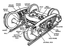
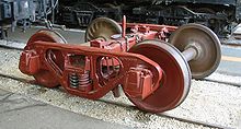
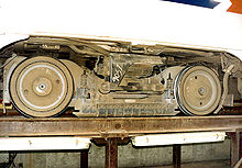
This article is about wheeled wagons and trolleys. For Bogey, see Bogie (disambiguation).Bettendorf-style freight car truck displayed at the Illinois Railway Museum. This one uses journal bearings in journal boxes.

A bogie (
 /ˈboʊɡi/ US dict: bō′·gē) is a wheeled wagon or trolley. In mechanics terms, a bogie is a chassis or framework carrying wheels, attached to a vehicle. It can be fixed in place, as on a cargo truck, mounted on a swivel, as on a railway carriage or locomotive, or sprung as in the suspension of a caterpillar tracked vehicle.
Contents
Railway
A bogie in the UK, or a wheel truck, or simply truck in North America, is a structure underneath a train to which axles (and, hence, wheels) are attached through bearings. In Indian English, bogie may also refer to an entire railway carriage.[1]
The first British railway to build coaches with bogies, instead of rigidly-mounted axles, was the Midland Railway in 1874.[2]
Bogies serve a number of purposes:[3]
- Support of the rail vehicle body.
- Stability on both straight and curved track.
- Ensuring ride comfort by absorbing vibration and minimizing centrifugal forces when the train runs on curves at high speed.
- Minimizing generation of track irregularities and rail abrasion.
Usually two bogies are fitted to each carriage, wagon or locomotive, one at each end. An alternate configuration often is used in articulated vehicles, which places the bogies (often jacobs bogies) under the connection between the carriages or wagons.
Most bogies have two axles as it is the simplest design,[3] but some cars designed for extremely heavy loads have been built with up to five axles per bogie. Heavy-duty cars may have more than two bogies using span bolsters to equalize the load and connect the bogies to the cars.
Usually the train floor is at a level above the bogies, but the floor of the car may be lower between bogies, such as for a double decker train to increase interior space while staying within height restrictions, or in easy-access, stepless-entry low-floor trains.
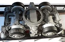
Key components of a bogie include:[3]
- The bogie frame itself. This can be of inside frame type where the main frame and bearings are between the wheels, or (more commonly) of outside frame type where the main frame and bearings are outside the wheels.
- Suspension to absorb shocks between the bogie frame and the rail vehicle body. Common types are coil springs, or rubber airbags.
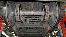
- At least one wheelset, composed of an axle with a bearings and wheel at each end.
- Axle box suspension to absorb shocks between the axle bearings and the bogie frame. The axle box suspension usually consists of a spring between the bogie frame and axle bearings to permit up and down movement, and sliders to prevent lateral movement. A more modern design uses solid rubber springs.
- Brake equipment. Two main types are used: brake shoes that are pressed against the tread of the wheel, and disc brakes and pads.
- In powered vehicles, some form of transmission, usually an electrically powered traction motors or a hydraulically powered torque converter.
The connections of the bogie with the rail vehicle allows a certain degree of rotational movement around a vertical axis pivot (bolster), with side bearers preventing excessive movement. More modern bolsterless bogie designs omit these features, instead taking advantage of the sideways movement of the suspension to permit rotational movement.[3]
Examples
BR1 bogie
The British Railways Mark 1 coach brought into production in 1950 utilised the BR1 bogie, which was rated to run at 90 mph (145 km/h). The wheels were cast as a one-piece item in a pair with their axle. The simple design involved the bogie resting on four leaf springs (one spring per wheel) which in turn were connected to the axles. The leaf springs were designed to absorb any movement or resonance and to have a damping effect to benefit ride quality.
Each spring was connected to the outermost edge of the axle by a roller bearing contained in oil-filled axle box. The oil had to be topped up at regular maintenance times to avoid the bearing running hot and seizing.
There was also a heavy-duty version designated BR2.
Commonwealth bogie
The Commonwealth bogie, manufactured by SKF or Timken, was introduced in the late 1950s for all BR Mark 1 vehicles. It was a heavy, cast-steel design weighing about 6.5 long tons (6.6 t)[4] with sealed roller bearings on the axle ends, avoiding the need to maintain axle box oil levels.
The leaf springs were replaced by coil springs (one per wheel) running vertically rather than horizontally. The advanced design gave a better ride quality than the BR1, being rated for 100 miles per hour (160 km/h).
The side frame of the bogie was usually of bar construction, with simple horn guides attached, allowing the axleboxes vertical movements between them. The axleboxes had a cast steel equaliser beam or bar resting on them. The bar had two steel coil springs placed on it and the bogie frame rested on the springs. The effect was to allow the bar to act as a compensating lever between the two axles and to use both springs to soften shocks from either axle. The bogie had a conventional bolster suspension with swing links carrying a spring plank.
B4 bogie
The B4 bogie was introduced in 1963. It was a fabricated steel design as versus cast iron and was lighter than the Commonwealth, weighing in at 5 long tons (5.08 t).[5] It also had a speed rating of 100 miles per hour (160 km/h).
Axle/spring connection was again with fitted roller bearings. However, now two coil springs rather than one were fitted per wheel.[6]
Only a very small amount of Mark 1 stock was fitted with the B4 bogie from new, it being used on the Mark 1 only to replace worn out BR1 bogies. The British Rail Mark 2 coach however carried the B4 bogies from new. A heavier duty version, the B5, was standard on Southern Region Mk1 based EMUs from the 1960s onwards. Some Mark 1 catering cars had mixed bogies—a B5 under the kitchen end, and a B4 under the seating end. Some of the B4 fitted Mark 2s, as well as many B4 fitted Mark 1 BGs were allowed to run at 110 miles per hour (180 km/h) with extra maintenance, particularly of the wheel profile, and more frequent exams.
BT10 Bogie
The BT10 bogie was introduced on the British Rail Mark 3 coach in the 1970s. Each wheel is separately connected to the bogie by a swing-arm axle.
There is dual suspension:
- primary suspension via a coil spring and damper mounted on each axle.
- secondary suspension via two air springs mounted on the pivot plank. This is connected to the bogie by pendulum links. A constant coach height is maintained by air valves.[7]
Locomotives
- Diesel and electric
Most diesel locomotives and electric locomotives are carried on bogies (trucks - US). Trucks used in the USA include AAR type A switcher truck, Blomberg B, HT-C truck and Flexicoil.[8]
- Steam
On a steam locomotive the leading wheels and trailing wheels may be mounted on bogies. Articulated locomotives (e.g. the Fairlie) have power bogies similar to those on diesel and electric locomotives.
Tramway
Modern
Tram bogies are much simpler in design because of their axle load, and the tighter curves found on tramways mean that tram bogies almost never have more than two axles. Furthermore, some tramways have steeper gradients and vertical as well as horizontal curves, which means that tram bogies often need to pivot on the horizontal axis as well.
Some articulated trams have bogies located under articulations, a setup referred to as a Jacobs bogie. Often low-floor trams are fitted with non-pivoting bogies and many tramway enthusiasts see this as a retrograde step, as it leads to more wear of both track and wheels and also significantly reduces the speed at which a tram can round a curve.[9] The only 100% low floor tram with pivoting bogies - Škoda ForCity - uses the Jacobs bogie.
Historic
In the past, many different types of bogie ("truck") have been used under tramcars, e.g. "Brill", "Peckham" and "maximum traction". A maximum traction truck has one driving axle with large wheels and one non-driving axle with smaller wheels. The bogie pivot is located off-centre so that more than half the weight rests on the driving axle.
Tracked vehicles
Some tanks and other tracked vehicles have bogies as external suspension components (see armoured fighting vehicle suspension). This type of bogie usually has two or more road wheels and some type of sprung suspension to smooth the ride across rough terrain. Bogie suspensions keep much of their components on the outside of the vehicle, saving internal space. Although vulnerable to antitank fire, they can often be repaired or replaced in the field.
Hybrid systems
The retractable stadium roof on Toronto's Roger's Centre utilized modified 'off the shelf' train bogies on a circular rail. The system was chosen for its proven reliability.
Rubber-tyred metro trains utilise a specialised version of railway bogies. As well as the standard running wheels (rubber instead of steel) there are additional horizontal guide wheels in front of and behind the running wheels.
Variable gauge axles
To overcome breaks of gauge some bogies are being fitted with variable gauge axles (VGA) so that they can operate on two different gauges. These include the SUW 2000 system from ZNTK.
Cleminson system
The Cleminson system is not a true bogie but serves a similar purpose. It was based on a patent of 1883 by James Cleminson[10] and was once popular on narrow-gauge rolling stock, e.g. on the Isle of Man Railway and Manx Northern Railway. The vehicle would have three axles and the outer two could pivot to adapt to curvature of the track. The pivoting was controlled by levers attached to the third (centre) axle which could slide sideways.[11]
Manufacturers
- Siemens [12] (link including 70 pages very detailed technical catalog)
- Bombardier [13]
- Alstom [14]
- Vickers Ruwolt [15]
See also
- Trailing wheel
- Wheel arrangement
- Wheelbase
- Wheel gauge
- Wheelset (rail transport)
References
- ^ http://www.oxfordadvancedlearnersdictionary.com/dictionary/bogie
- ^ Jenkinson, David (1988). British Railway Carriages of the 20th Century - Volume 1: The end of an era, 1901-22. London: Guild Publishing. p. 10. CN 8130.
- ^ a b c d Isao Okamoto (December 1998). "How Bogies Work". Japan Railway & Transport Review (18): 52–61. http://www.jrtr.net/jrtr18/pdf/f52_technology.pdf.
- ^ Parkin, Keith (1991). British Railways Mark 1 Coaches. Penryn: Pendragon. p. 35. ISBN 0 906899 49 4.
- ^ Parkin 1991, p. 37
- ^ Unofficial West Somerset Railway website - Bogies
- ^ Roger Barnett - British Rail’s InterCity 125 and 225
- ^ http://www.hosam.com/emd/emd6a.html
- ^ "ČVUT.cz - Čapek, Kolář" (PDF). http://www.railway2007.fd.cvut.cz/proceedings/Capek+Kolar.pdf. Retrieved 2010-05-12.
- ^ http://www.icevirtuallibrary.com/docserver/fulltext/imotp.1897.19461.pdf?expires=1315520526&id=id&accname=guest&checksum=AD521ED02561C3CF38D1772ECF1ACA2B
- ^ http://www.festipedia.org.uk/wiki/Cleminson_Flexible_Six-Wheeled_Waggon
- ^ http://www.mobility.siemens.com/mobility/global/en/urban-mobility/rail-solutions/components-and-systems/Pages/components-and-systems.aspx#Bogies%20%E2%80%93%20a%20full%20range%20for%20high-quality%20passenger%20transport
- ^ http://www.bombardier.com/en/transportation/products-services/bogies
- ^ http://www.alstom.com/transport/news-and-events/events/archives/reveal-AGV/technologies
- ^ http://www.sffej.net/vickers/railway.html
External links
- (English) TRUCK (bogie) with tyres
- (English) Arbel Faufet Rail Bogies
- (English) Track modelling
Locomotive running and valve gear Valve gear types Allan · Baker · Bagnall-Price · Baguley · Bulleid · Caprotti · Gooch · Gresley · Joy · Kuhn slide · Lentz · Southern · Stephenson · WalschaertsBogie types Other running gear elements Adams axle · Beugniot lever · Coupled wheel · Driving wheel · Gölsdorf axle · Klien-Lindner axle · Leading wheel · Luttermöller axle · Radial axle · Trailing wheelCategories:- Rail technologies
- Locomotive parts
- Vehicle technology
Wikimedia Foundation. 2010.

