- 3D projection
-
Part of a series on: Graphical projection - Parallel projection
- Orthographic projection
- Multiviews
- Plan, or floor plan
- Section
- Elevation
- Auxiliary
- Axonometric projection (i.e. pictorials)
- Isometric projection
- Dimetric projection
- Trimetric projection
- Multiviews
- Oblique projection
- Cavalier projection
- Cabinet projection
- Orthographic projection
- Perspective projection
- Linear perspective
- One-point perspective
- Two-point perspective
- Three-point perspective
- Zero-point perspective
- Curvilinear perspective
- Reverse perspective
- Linear perspective
Other- 3D projection
- Stereographic projection
- Anamorphic projection
Views- Bird's-eye view/Aerial view
- Detail view
- 3/4 perspective
- Cutaway drawing
- Exploded view drawing
- Fisheye
- Fixed 3D
- Panorama
- Top-down perspective
- Worm's-eye view
- Zoom
3D projection is any method of mapping three-dimensional points to a two-dimensional plane. As most current methods for displaying graphical data are based on planar two-dimensional media, the use of this type of projection is widespread, especially in computer graphics, engineering and drafting.
Contents
Orthographic projection
Main article: Orthographic projectionWhen the human eye looks at a scene, objects in the distance appear smaller than objects close by. Orthographic projection ignores this effect to allow the creation of to-scale drawings for construction and engineering.
Orthographic projections are a small set of transforms often used to show profile, detail or precise measurements of a three dimensional object. Common names for orthographic projections include plane, cross-section, bird's-eye, and elevation.
If the normal of the viewing plane (the camera direction) is parallel to one of the primary axes (which is the x, y, or z axis), the mathematical transformation is as follows; To project the 3D point ax, ay, az onto the 2D point bx, by using an orthographic projection parallel to the y axis (profile view), the following equations can be used:
- bx = sxax + cx
- by = szaz + cz
where the vector s is an arbitrary scale factor, and c is an arbitrary offset. These constants are optional, and can be used to properly align the viewport. Using matrix multiplication, the equations become:
 .
.
While orthographically projected images represent the three dimensional nature of the object projected, they do not represent the object as it would be recorded photographically or perceived by a viewer observing it directly. In particular, parallel lengths at all points in an orthographically projected image are of the same scale regardless of whether they are far away or near to the virtual viewer. As a result, lengths near to the viewer are not foreshortened as they would be in a perspective projection.
Perspective projection
See also: Transformation matrixSee also: Camera matrixWhen the human eye looks at a scene, objects in the distance appear smaller than objects close by - this is known as perspective. While orthographic projection ignores this effect to allow accurate measurements, perspective definition shows distant objects as smaller to provide additional realism.
The perspective projection requires greater definition. A conceptual aid to understanding the mechanics of this projection involves treating the 2D projection as being viewed through a camera viewfinder. The camera's position, orientation, and field of view control the behavior of the projection transformation. The following variables are defined to describe this transformation:
 - the 3D position of a point A that is to be projected.
 - the 3D position of a point C representing the camera.
 - The orientation of the camera (represented, for instance, by Tait–Bryan angles).
 - the viewer's position relative to the display surface.[1]
Which results in:
 - the 2D projection of
  .
.
When
 and
and  the 3D vector
  is projected to the 2D vector
  .
.Otherwise, to compute
we first define a vector  as the position of point A with respect to a coordinate system defined by the camera, with origin in C and rotated by
  with respect to the initial coordinate system. This is achieved by subtracting
  from and then applying a rotation by
  to the result. This transformation is often called a camera transform, and can be expressed as follows, expressing the rotation in terms of rotations about the x, y, and z axes (these calculations assume that the axes are ordered as a left-handed system of axes): [2] [3]
This representation corresponds to rotating by three Euler angles (more properly, Tait–Bryan angles), using the xyz convention, which can be interpreted either as "rotate about the extrinsic axes (axes of the scene) in the order z, y, x (reading right-to-left)" or "rotate about the intrinsic axes (axes of the camera) in the order x, y, z) (reading left-to-right)". Note that if the camera is not rotated (
 ), then the matrices drop out (as identities), and this reduces to simply a shift:
Alternatively, without using matrices, (note that the signs of angles are inconsistent with matrix form):
This transformed point can then be projected onto the 2D plane using the formula (here, x/y is used as the projection plane; literature also may use x/z):[4]
Or, in matrix form using homogeneous coordinates, the system
in conjunction with an argument using similar triangles, leads to division by the homogeneous coordinate, giving
The distance of the viewer from the display surface,
 , directly relates to the field of view, where
  is the viewed angle. (Note: This assumes that you map the points (-1,-1) and (1,1) to the corners of your viewing surface)
The above equations can also be rewritten as:
In which
 is the display size,
  is the recording surface size (CCD or film),
  is the distance from the recording surface to the entrance pupil (camera center), and
  is the distance, from the 3D point being projected, to the entrance pupil.
Subsequent clipping and scaling operations may be necessary to map the 2D plane onto any particular display media.
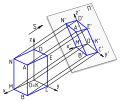
Diagram

To determine which screen x-coordinate corresponds to a point at Ax,Az multiply the point coordinates by:
where
- Bx is the screen x coordinate
- Ax is the model x coordinate
- Bz is the focal length—the axial distance from the camera center to the image plane
- Az is the subject distance.
Because the camera is in 3D, the same works for the screen y-coordinate, substituting y for x in the above diagram and equation.
See also
- Computer graphics
- 3D computer graphics
- Graphics card
- Transform and lighting
- Texture mapping
- Perspective (graphical)
- Camera matrix
- Homography
- Homogeneous coordinates
References
- ^ Ingrid Carlbom, Joseph Paciorek (1978). "Planar Geometric Projections and Viewing Transformations". ACM Computing Surveys 10 (4): 465–502. doi:10.1145/356744.356750. http://www.cs.uns.edu.ar/cg/clasespdf/p465carlbom.pdf.
- ^ Riley, K F (2006). Mathematical Methods for Physics and Engineering. Cambridge University Press. pp. 931, 942. doi:10.2277/0521679710. ISBN 0-521-67971-0.
- ^ Goldstein, Herbert (1980). Classical Mechanics (2nd ed.). Reading, Mass.: Addison-Wesley Pub. Co.. pp. 146–148. ISBN 0-201-02918-9.
- ^ Sonka, M; Hlavac, V; Boyle, R (1995). Image Processing, Analysis & Machine Vision (2nd ed.). Chapman and Hall. pp. 14. ISBN 0-412-45570-6
External links
Further reading
- Kenneth C. Finney (2004). 3D Game Programming All in One. Thomson Course. pp. 93. ISBN 978-1-59200-136-1. http://books.google.com/?id=cknGqaHwPFkC&pg=PA93&dq=%223D+projection%22.
Categories:- Linear algebra
- Euclidean solid geometry
- Projective geometry
- 3D computer graphics
- 3D imaging
- Graphical projections
- Functions and mappings
- Parallel projection


Wikimedia Foundation. 2010.