- Texture mapping
-
"Texture maps" redirects here. For the 2003 ambient album, see Texture Maps: The Lost Pieces Vol. 3.
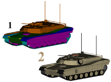 1 = 3D model without textures
2 = 3D model with texturesTexture mapping is a method for adding detail, surface texture (a bitmap or raster image), or color to a computer-generated graphic or 3D model. Its application to 3D graphics was pioneered by Dr Edwin Catmull in his Ph.D. thesis of 1974.
Contents
Texture mapping
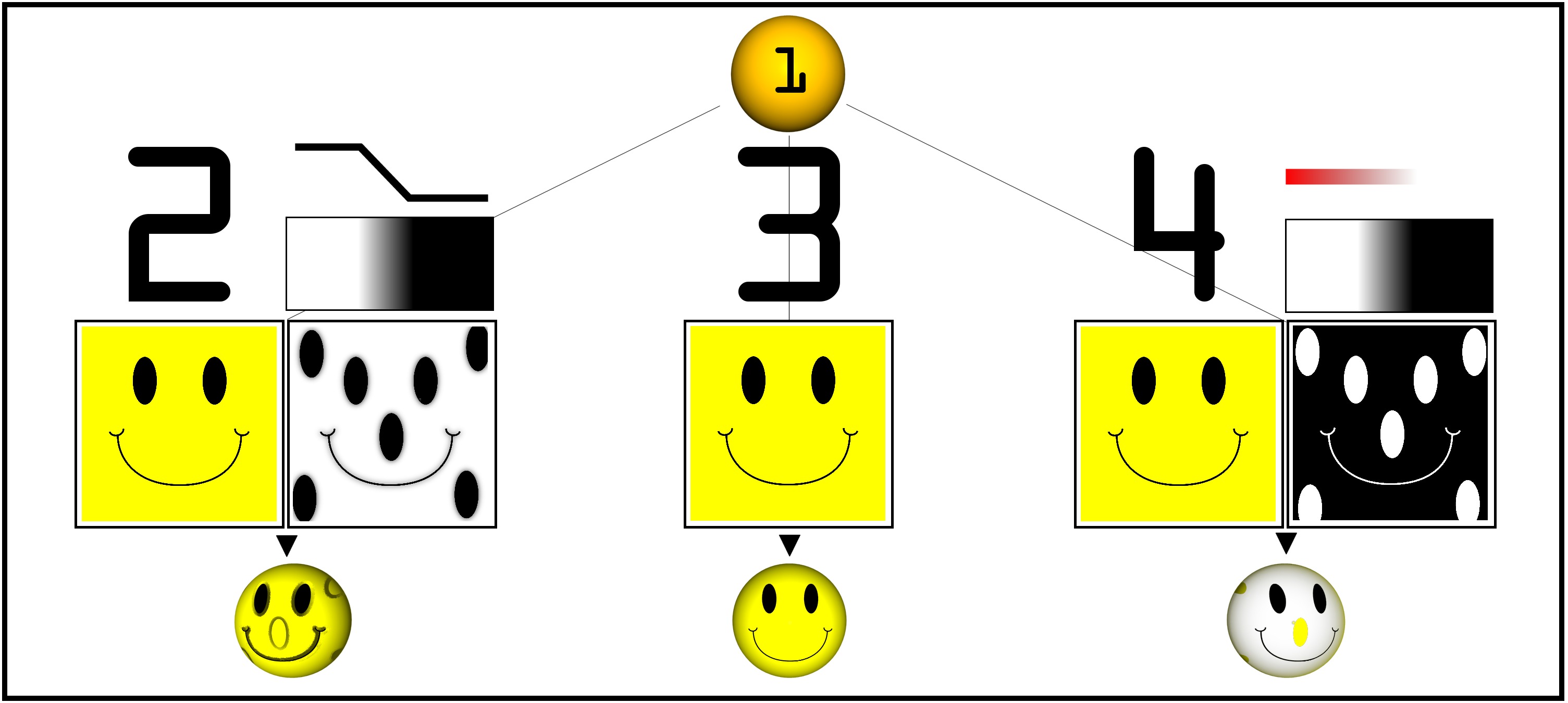
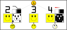 Examples of multitexturing (click for larger image);
1: Untextured sphere, 2: Texture and bump maps, 3: Texture map only, 4: Opacity and texture maps.A texture map is applied (mapped) to the surface of a shape or polygon.[1] This process is akin to applying patterned paper to a plain white box. Every vertex in a polygon is assigned a texture coordinate (which in the 2d case is also known as a UV coordinate) either via explicit assignment or by procedural definition. Image sampling locations are then interpolated across the face of a polygon to produce a visual result that seems to have more richness than could otherwise be achieved with a limited number of polygons. Multitexturing is the use of more than one texture at a time on a polygon.[2] For instance, a light map texture may be used to light a surface as an alternative to recalculating that lighting every time the surface is rendered. Another multitexture technique is bump mapping, which allows a texture to directly control the facing direction of a surface for the purposes of its lighting calculations; it can give a very good appearance of a complex surface, such as tree bark or rough concrete, that takes on lighting detail in addition to the usual detailed coloring. Bump mapping has become popular in recent video games as graphics hardware has become powerful enough to accommodate it in real-time.
The way the resulting pixels on the screen are calculated from the texels (texture pixels) is governed by texture filtering. The fastest method is to use the nearest-neighbour interpolation, but bilinear interpolation or trilinear interpolation between mipmaps are two commonly used alternatives which reduce aliasing or jaggies. In the event of a texture coordinate being outside the texture, it is either clamped or wrapped.
Perspective correctness
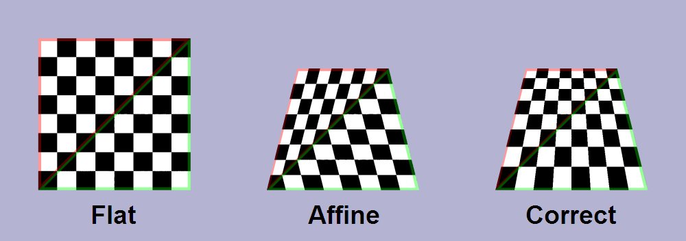
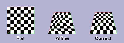 Because affine texture mapping does not take into account the depth information about a polygon's vertices, where the polygon is not perpendicular to the viewer it produces a noticeable defect.
Texture coordinates are specified at each vertex of a given triangle, and these coordinates are interpolated using an extended Bresenham's line algorithm. If these texture coordinates are linearly interpolated across the screen, the result is affine texture mapping. This is a fast calculation, but there can be a noticeable discontinuity between adjacent triangles when these triangles are at an angle to the plane of the screen (see figure at right – textures (the checker boxes) appear bent).
Perspective correct texturing accounts for the vertices' positions in 3D space, rather than simply interpolating a 2D triangle. This achieves the correct visual effect, but it is slower to calculate. Instead of interpolating the texture coordinates directly, the coordinates are divided by their depth (relative to the viewer), and the reciprocal of the depth value is also interpolated and used to recover the perspective-correct coordinate. This correction makes it so that in parts of the polygon that are closer to the viewer the difference from pixel to pixel between texture coordinates is smaller (stretching the texture wider), and in parts that are farther away this difference is larger (compressing the texture).
- Affine texture mapping directly interpolates a texture coordinate
 between two endpoints
  and
and  :
:
 where
where 
- Perspective correct mapping interpolates after dividing by depth
 , then uses its interpolated reciprocal to recover the correct coordinate:
All modern 3D graphics hardware implements perspective correct texturing.
 Doom renders vertical spans (walls) with affine texture mapping.
 Screen space sub division techniques. Top left: Quake-like, top right: bilinear, bottom left: const-z
Classic texture mappers generally did only simple mapping with at most one lighting effect, and the perspective correctness was about 16 times more expensive. To achieve two goals - faster arithmetic results, and keeping the arithmetic mill busy at all times - every triangle is further subdivided into groups of about 16 pixels. For perspective texture mapping without hardware support, a triangle is broken down into smaller triangles for rendering, which improves details in non-architectural applications. Software renderers generally preferred screen subdivision because it has less overhead. Additionally they try to do linear interpolation along a line of pixels to simplify the set-up (compared to 2d affine interpolation) and thus again the overhead (also affine texture-mapping does not fit into the low number of registers of the x86 CPU; the 68000 or any RISC is much more suited). For instance, Doom restricted the world to vertical walls and horizontal floors/ceilings. This meant the walls would be a constant distance along a vertical line and the floors/ceilings would be a constant distance along a horizontal line. A fast affine mapping could be used along those lines because it would be correct. A different approach was taken for Quake, which would calculate perspective correct coordinates only once every 16 pixels of a scanline and linearly interpolate between them, effectively running at the speed of linear interpolation because the perspective correct calculation runs in parallel on the co-processor.[3] The polygons are rendered independently, hence it may be possible to switch between spans and columns or diagonal directions depending on the orientation of the polygon normal to achieve a more constant z, but the effort seems not to be worth it.
Another technique was subdividing the polygons into smaller polygons, like triangles in 3d-space or squares in screen space, and using an affine mapping on them. The distortion of affine mapping becomes much less noticeable on smaller polygons. Yet another technique was approximating the perspective with a faster calculation, such as a polynomial. Still another technique uses 1/z value of the last two drawn pixels to linearly extrapolate the next value. The division is then done starting from those values so that only a small remainder has to be divided,[4] but the amount of bookkeeping makes this method too slow on most systems. Finally, some programmers extended the constant distance trick used for Doom by finding the line of constant distance for arbitrary polygons and rendering along it.
Resolution
The resolution of a texture map is usually given as a width in pixels, assuming the map is square. For example, a 1K texture has a resolution of 1024 x 1024, or 1,048,576 pixels.[citation needed]
Graphics cards cannot render texture maps beyond a threshold that depends on their hardware, possibly the amount of available RAM.[citation needed]
See also
- Mipmapping
- Bump mapping
- Clamping
- Cube mapping
- Daytona USA (video game)
- Displacement mapping
- Environment mapping
- Edwin Catmull
- Image analogy
- Lightmap
- MClone
- Normal mapping
- Parametrization
- Parallax mapping
- Relief mapping (computer graphics)
- Texture synthesis
- Texture atlas
- Texture artist
- Texture filtering
- Texture splatting – a technique for combining textures.
- UV Mapping
- UVW Mapping
- Wrapping (graphics)
References
- ^ Jon Radoff, Anatomy of an MMORPG, http://radoff.com/blog/2008/08/22/anatomy-of-an-mmorpg/
- ^ Blythe, David. Advanced Graphics Programming Techniques Using OpenGL. Siggraph 1999. (see: Multitexture)
- ^ Abrash, Michael. Michael Abrash's Graphics Programming Black Book Special Edition. The Coriolis Group, Scottsdale Arizona, 1997. ISBN 1-57610-174-6 (PDF) (Chapter 70, pg. 1282)
- ^ US 5739818, Spackman, John Neil, "Apparatus and method for performing perspectively correct interpolation in computer graphics", issued 1998-04-14
External links
- Introduction into texture mapping using C and SDL
- Programming a textured terrain using XNA/DirectX, from www.riemers.net
- Perspective correct texturing
- Time Texturing Texture mapping with bezier lines
- Polynomial Texture Mapping Interactive Relighting for Photos
- 3 Métodos de interpolación a partir de puntos (in spanish) Methods that can be used to interpolate a texture knowing the texture coords at the vertices of a polygon
Categories: - Affine texture mapping directly interpolates a texture coordinate


Wikimedia Foundation. 2010.