- RS-232
-
This article is about the RS-232 standard. For RS-232 variants, see serial port.
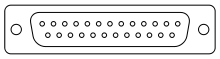 A 25 pin connector as described in the RS-232 standard
In telecommunications, RS-232 (Recommended Standard 232) is the traditional name for a series of standards for serial binary single-ended data and control signals connecting between a DTE (Data Terminal Equipment) and a DCE (Data Circuit-terminating Equipment). It is commonly used in computer serial ports. The standard defines the electrical characteristics and timing of signals, the meaning of signals, and the physical size and pin out of connectors. The current version of the standard is TIA-232-F Interface Between Data Terminal Equipment and Data Circuit-Terminating Equipment Employing Serial Binary Data Interchange, issued in 1997.
An RS-232 port was once a standard feature of a personal computer for connections to modems, printers, mice, data storage, un-interruptible power supplies, and other peripheral devices. However, the limited transmission speed, relatively large voltage swing, and large standard connectors motivated development of the universal serial bus which has displaced RS-232 from most of its peripheral interface roles. Many modern personal computers have no RS-232 ports and must use an external converter to connect to older peripherals. Some RS-232 devices are still found especially in industrial machines or scientific instruments.
Contents
Scope of the standard
The Electronic Industries Association (EIA) standard RS-232-C[1] as of 1969 defines:
- Electrical signal characteristics such as voltage levels, signaling rate, timing and slew-rate of signals, voltage withstand level, short-circuit behavior, and maximum load capacitance.
- Interface mechanical characteristics, pluggable connectors and pin identification.
- Functions of each circuit in the interface connector.
- Standard subsets of interface circuits for selected telecom applications.
The standard does not define such elements as
- character encoding (for example, ASCII, Baudot code or EBCDIC)
- the framing of characters in the data stream (bits per character, start/stop bits, parity)
- protocols for error detection or algorithms for data compression
- bit rates for transmission, although the standard says it is intended for bit rates lower than 20,000 bits per second. Many modern devices support speeds of 115,200 bit/s and above
- power supply to external devices.
Details of character format and transmission bit rate are controlled by the serial port hardware, often a single integrated circuit called a UART that converts data from parallel to asynchronous start-stop serial form. Details of voltage levels, slew rate, and short-circuit behavior are typically controlled by a line driver that converts from the UART's logic levels to RS-232 compatible signal levels, and a receiver that converts from RS-232 compatible signal levels to the UART's logic levels.
History
RS-232 was first introduced in 1962.[2] The original DTEs were electromechanical teletypewriters, and the original DCEs were (usually) modems. When electronic terminals (smart and dumb) began to be used, they were often designed to be interchangeable with teletypes, and so supported RS-232. The C revision of the standard was issued in 1969 in part to accommodate the electrical characteristics of these devices.[citation needed]
Since application to devices such as computers, printers, test instruments, and so on was not considered by the standard, designers implementing an RS-232 compatible interface on their equipment often interpreted the requirements idiosyncratically. Common problems were non-standard pin assignment of circuits on connectors, and incorrect or missing control signals. The lack of adherence to the standards produced a thriving industry of breakout boxes, patch boxes, test equipment, books, and other aids for the connection of disparate equipment. A common deviation from the standard was to drive the signals at a reduced voltage. Some manufacturers therefore built transmitters that supplied +5 V and -5 V and labeled them as "RS-232 compatible".[citation needed]
Later personal computers (and other devices) started to make use of the standard so that they could connect to existing equipment. For many years, an RS-232-compatible port was a standard feature for serial communications, such as modem connections, on many computers. It remained in widespread use into the late 1990s. In personal computer peripherals, it has largely been supplanted by other interface standards, such as USB. RS-232 is still used to connect older designs of peripherals, industrial equipment (such as PLCs), console ports, and special purpose equipment, such as a cash drawer for a cash register.[citation needed]
The standard has been renamed several times during its history as the sponsoring organization changed its name, and has been variously known as EIA RS-232, EIA 232, and most recently as TIA 232. The standard continued to be revised and updated by the Electronic Industries Alliance and since 1988 by the Telecommunications Industry Association (TIA).[3] Revision C was issued in a document dated August 1969. Revision D was issued in 1986. The current revision is TIA-232-F Interface Between Data Terminal Equipment and Data Circuit-Terminating Equipment Employing Serial Binary Data Interchange, issued in 1997. Changes since Revision C have been in timing and details intended to improve harmonization with the CCITT standard V.24, but equipment built to the current standard will interoperate with older versions.[citation needed]
Related ITU-T standards include V.24 (circuit identification) and V.28 (signal voltage and timing characteristics).[citation needed]
Limitations of the standard
Because the application of RS-232 has extended far beyond the original purpose of interconnecting a terminal with a modem, successor standards have been developed to address the limitations. Issues with the RS-232 standard include:[4]
- The large voltage swings and requirement for positive and negative supplies increases power consumption of the interface and complicates power supply design. The voltage swing requirement also limits the upper speed of a compatible interface.
- Single-ended signaling referred to a common signal ground limits the noise immunity and transmission distance.
- Multi-drop connection among more than two devices is not defined. While multi-drop "work-arounds" have been devised, they have limitations in speed and compatibility.
- Asymmetrical definitions of the two ends of the link make the assignment of the role of a newly developed device problematic; the designer must decide on either a DTE-like or DCE-like interface and which connector pin assignments to use.
- The handshaking and control lines of the interface are intended for the setup and takedown of a dial-up communication circuit; in particular, the use of handshake lines for flow control is not reliably implemented in many devices.
- No method is specified for sending power to a device. While a small amount of current can be extracted from the DTR and RTS lines, this is only suitable for low power devices such as mice.
- The 25-way connector recommended in the standard is large compared to current practice.
Role in modern personal computers
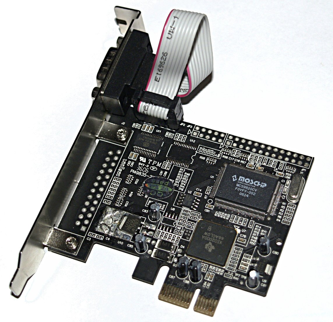
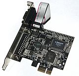 PCI Express x1 card with one RS-232 portMain article: Serial port
In the book, PC 97 Hardware Design Guide,[5] Microsoft deprecated support for the RS-232 compatible serial port of the original IBM PC design. Today, RS-232 has mostly been replaced in personal computers by USB for local communications. Compared with RS-232, USB is faster, uses lower voltages, and has connectors that are simpler to connect and use. However, USB is limited by standard to no more than 5 meters of cable, thus favoring RS-232 when longer distances are needed. Both standards have software support in popular operating systems. USB is designed to make it easy for device drivers to communicate with hardware. However, there is no direct analog to the terminal programs used to let users communicate directly with serial ports. USB is more complex than the RS-232 standard because it includes a protocol for transferring data to devices. This requires more software to support the protocol used. RS-232 only standardizes the voltage of signals and the functions of the physical interface pins. Serial ports of personal computers are also sometimes used to directly control various hardware devices, such as relays or lamps, since the control lines of the interface can be easily manipulated by software. This isn't feasible with USB, which requires some form of receiver to decode the serial data.
As an alternative, USB docking ports are available which can provide connectors for a keyboard, mouse, one or more serial ports, and one or more parallel ports. Corresponding device drivers are required for each USB-connected device to allow programs to access these USB-connected devices as if they were the original directly connected peripherals. Devices that convert USB to RS-232 may not work with all software on all personal computers and may cause a reduction in bandwidth along with higher latency.
Personal computers may use a serial port to interface to devices such as uninterruptible power supplies. In some cases, serial data is not exchanged, but the control lines are used to signal conditions such as loss of power or low battery alarms.
Many fields (for example, laboratory automation, surveying) provide a continued demand for RS-232 I/O due to sustained use of very expensive but aging equipment. It is often far cheaper to continue to use RS-232 than it is to replace the equipment. Additionally, modern industrial automation equipment, such as PLCs, VFDs, servo drives, and CNC equipment are programmable via RS-232. Some manufacturers have responded to this demand: Toshiba re-introduced the DE-9M connector on the Tecra laptop.
Serial ports with RS-232 are also commonly used to communicate to headless systems such as servers, where no monitor or keyboard is installed, during boot when operating system isn't running yet and therefore no network connection is possible. An RS-232 serial port can communicate to some embedded systems such as routers as an alternative to network mode of monitoring.
Standard details
In RS-232, user data is sent as a time-series of bits. Both synchronous and asynchronous transmissions are supported by the standard. In addition to the data circuits, the standard defines a number of control circuits used to manage the connection between the DTE and DCE. Each data or control circuit only operates in one direction, that is, signaling from a DTE to the attached DCE or the reverse. Since transmit data and receive data are separate circuits, the interface can operate in a full duplex manner, supporting concurrent data flow in both directions. The standard does not define character framing within the data stream, or character encoding.
Voltage levels
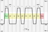 Diagrammatic oscilloscope trace of voltage levels for an uppercase ASCII "K" character (0x4b) with 1 start bit, 8 data bits, 1 stop bit
.
The RS-232 standard defines the voltage levels that correspond to logical one and logical zero levels for the data transmission and the control signal lines. Valid signals are plus or minus 3 to 15 volts; the ±3 V range near zero volts is not a valid RS-232 level. The standard specifies a maximum open-circuit voltage of 25 volts: signal levels of ±5 V, ±10 V, ±12 V, and ±15 V are all commonly seen depending on the power supplies available within a device. RS-232 drivers and receivers must be able to withstand indefinite short circuit to ground or to any voltage level up to ±25 volts. The slew rate, or how fast the signal changes between levels, is also controlled.
For data transmission lines (TxD, RxD and their secondary channel equivalents) logic one is defined as a negative voltage, the signal condition is called marking, and has the functional significance. Logic zero is positive and the signal condition is termed spacing. Control signals are logically inverted with respect to what one sees on the data transmission lines. When one of these signals is active, the voltage on the line will be between +3 to +15 volts. The inactive state for these signals is the opposite voltage condition, between −3 and −15 volts. Examples of control lines include request to send (RTS), clear to send (CTS), data terminal ready (DTR), and data set ready (DSR).
Because the voltage levels are higher than logic levels typically used by integrated circuits, special intervening driver circuits are required to translate logic levels. These also protect the device's internal circuitry from short circuits or transients that may appear on the RS-232 interface, and provide sufficient current to comply with the slew rate requirements for data transmission.
Because both ends of the RS-232 circuit depend on the ground pin being zero volts, problems will occur when connecting machinery and computers where the voltage between the ground pin on one end, and the ground pin on the other is not zero. This may also cause a hazardous ground loop. Use of a common ground limits RS-232 to applications with relatively short cables. If the two devices are far enough apart or on separate power systems, the local ground connections at either end of the cable will have differing voltages; this difference will reduce the noise margin of the signals. Balanced, differential, serial connections such as USB, RS-422 and RS-485 can tolerate larger ground voltage differences because of the differential signaling.[6]
Unused interface signals terminated to ground will have an undefined logic state. Where it is necessary to permanently set a control signal to a defined state, it must be connected to a voltage source that asserts the logic 1 or logic 0 level. Some devices provide test voltages on their interface connectors for this purpose.
Connectors
RS-232 devices may be classified as Data Terminal Equipment (DTE) or Data Communication Equipment (DCE); this defines at each device which wires will be sending and receiving each signal. The standard recommended but did not make mandatory the D-subminiature 25 pin connector. In general and according to the standard, terminals and computers have male connectors with DTE pin functions, and modems have female connectors with DCE pin functions. Other devices may have any combination of connector gender and pin definitions. Many terminals were manufactured with female terminals but were sold with a cable with male connectors at each end; the terminal with its cable satisfied the recommendations in the standard.
Presence of a 25 pin D-sub connector does not necessarily indicate an RS-232-C compliant interface. For example, on the original IBM PC, a male D-sub was an RS-232-C DTE port (with a non-standard current loop interface on reserved pins), but the female D-sub connector was used for a parallel Centronics printer port. Some personal computers put non-standard voltages or signals on some pins of their serial ports.
The standard specifies 20 different signal connections. Since most devices use only a few signals, smaller connectors can often be used.
Pinouts
The following table lists commonly used RS-232 signals and pin assignments.[7] See serial port for non-standard variations including the popular DE-9 connector.
Signal Origin DB-25 pin Name Typical purpose Abbreviation DTE DCE Data Terminal Ready Indicates presence of DTE to DCE. DTR ● 20 Data Carrier Detect DCE is connected to the telephone line. DCD ● 8 Data Set Ready DCE is ready to receive commands or data. DSR ● 6 Ring Indicator DCE has detected an incoming ring signal on the telephone line. RI ● 22 Request To Send DTE requests the DCE prepare to receive data. RTS ● 4 Clear To Send Indicates DCE is ready to accept data. CTS ● 5 Transmitted Data Carries data from DTE to DCE. TxD ● 2 Received Data Carries data from DCE to DTE. RxD ● 3 Common Ground GND common 7 Protective Ground PG common 1 The signals are named from the standpoint of the DTE. The ground signal is a common return for the other connections. The DB-25 connector includes a second "protective ground" on pin 1.
Data can be sent over a secondary channel (when implemented by the DTE and DCE devices), which is equivalent to the primary channel. Pin assignments are described in following table:
Signal Pin Common Ground 7 (same as primary) Secondary Transmitted Data (STD) 14 Secondary Received Data (SRD) 16 Secondary Request To Send (SRTS) 19 Secondary Clear To Send (SCTS) 13 Secondary Carrier Detect (SDCD) 12 Cables
Main article: Serial cableThe standard does not define a maximum cable length but instead defines the maximum capacitance that a compliant drive circuit must tolerate. A widely used rule of thumb indicates that cables more than 50 feet (15 metres) long will have too much capacitance, unless special cables are used. By using low-capacitance cables, full speed communication can be maintained over larger distances up to about 1,000 feet.[8] For longer distances, other signal standards are better suited to maintain high speed.
Since the standard definitions are not always correctly applied, it is often necessary to consult documentation, test connections with a breakout box, or use trial and error to find a cable that works when interconnecting two devices. Connecting a fully standard-compliant DCE device and DTE device would use a cable that connects identical pin numbers in each connector (a so-called "straight cable"). "Gender changers" are available to solve gender mismatches between cables and connectors. Connecting devices with different types of connectors requires a cable that connects the corresponding pins according to the table above. Cables with 9 pins on one end and 25 on the other are common. Manufacturers of equipment with 8P8C connectors usually provide a cable with either a DB-25 or DE-9 connector (or sometimes interchangeable connectors so they can work with multiple devices). Poor-quality cables can cause false signals by crosstalk between data and control lines (such as Ring Indicator). If a given cable will not allow a data connection, especially if a Gender changer is in use, a Null modem may be necessary.
Conventions
For functional communication through a serial port interface, conventions of bit rate, character framing, communications protocol, character encoding, data compression, and error detection, not defined in RS 232, must be agreed to by both sending and receiving equipment. For example, consider the serial ports of the original IBM PC. This implementation used an 8250 UART using asynchronous start-stop character formatting with 7 or 8 data bits per frame, usually ASCII character coding, and data rates programmable between 75 bits per second and 115,200 bits per second. Data rates above 20,000 bits per second are out of the scope of the standard, although higher data rates are sometimes used by commercially manufactured equipment. Since most RS-232 devices do not have automatic baud rate detection, users must manually set the baud rate (and all other parameters) at both ends of the RS-232 connection.
In the particular case of the IBM PC, as with most UART chips including the 8250 UART used by the IBM PC, baud rates were programmable with arbitrary values. This allowed a PC to be connected to devices not using the rates typically used with modems. Not all baud rates can be programmed, due to the clock frequency of the 8250 UART in the PC, and the granularity of the baud rate setting. This includes the baud rate of MIDI, 31,250 bits per second, which is generally not achievable by a standard IBM PC serial port. [9] MIDI-to-RS-232 interfaces designed for the IBM PC include baud rate translation hardware to adjust the baud rate of the MIDI data to something that the IBM PC can support, for example 19,200 or 38,400 bits per second.
RTS/CTS handshaking
Further information: Hardware flow controlIn older versions of the specification, RS-232's use of the RTS and CTS lines is asymmetric: The DTE asserts RTS to indicate a desire to transmit to the DCE, and the DCE asserts CTS in response to grant permission. This allows for half-duplex modems that disable their transmitters when not required, and must transmit a synchronization preamble to the receiver when they are re-enabled. This scheme is also employed on present-day RS-232 to RS-485 converters, where the RS-232's RTS signal is used to ask the converter to take control of the RS-485 bus - a concept that doesn't otherwise exist in RS-232. There is no way for the DTE to indicate that it is unable to accept data from the DCE.
A non-standard symmetric alternative, commonly called "RTS/CTS handshaking," was developed by various equipment manufacturers. In this scheme, CTS is no longer a response to RTS; instead, CTS indicates permission from the DCE for the DTE to send data to the DCE, and RTS indicates permission from the DTE for the DCE to send data to the DTE. RTS and CTS are controlled by the DTE and DCE respectively, each independent of the other. This was eventually codified in version RS-232-E (actually TIA-232-E by that time) by defining a new signal, "RTR (Ready to Receive)," which is CCITT V.24 circuit 133. TIA-232-E and the corresponding international standards were updated to show that circuit 133, when implemented, shares the same pin as RTS (Request to Send), and that when 133 is in use, RTS is assumed by the DCE to be ON at all times.[10]
Thus, with this alternative usage, one can think of RTS asserted (positive voltage, logic 0) meaning that the DTE is indicating it is "ready to receive" from the DCE, rather than requesting permission from the DCE to send characters to the DCE.
Note that equipment using this protocol must be prepared to buffer some extra data, since a transmission may have begun just before the control line state change.
RTS/CTS handshaking is an example of hardware flow control. However, "hardware flow control" in the description of the options available on an RS-232-equipped device does not always mean RTS/CTS handshaking.
3-wire and 5-wire RS-232
A minimal "3-wire" RS-232 connection consisting only of transmit data, receive data, and ground, is commonly used when the full facilities of RS-232 are not required. Even a two-wire connection (data and ground) can be used if the data flow is one way (for example, a digital postal scale that periodically sends a weight reading, or a GPS receiver that periodically sends position, if no configuration via RS-232 is necessary). When only hardware flow control is required in addition to two-way data, the RTS and CTS lines are added in a 5-wire version.
Seldom used features
The EIA-232 standard specifies connections for several features that are not used in most implementations. Their use requires the 25-pin connectors and cables, and of course both the DTE and DCE must support them.
Signal rate selection
The DTE or DCE can specify use of a "high" or "low" signaling rate. The rates as well as which device will select the rate must be configured in both the DTE and DCE. The prearranged device selects the high rate by setting pin 23 to ON.
Loopback testing
Many DCE devices have a loopback capability used for testing. When enabled, signals are echoed back to the sender rather than being sent on to the receiver. If supported, the DTE can signal the local DCE (the one it is connected to) to enter loopback mode by setting pin 18 to ON, or the remote DCE (the one the local DCE is connected to) to enter loopback mode by setting pin 21 to ON. The latter tests the communications link as well as both DCE's. When the DCE is in test mode it signals the DTE by setting pin 25 to ON.
A commonly used version of loopback testing doesn't involve any special capability of either end. A hardware loopback is simply a wire connecting complementary pins together in the same connector (see loopback).
Loopback testing is often performed with a specialized DTE called a bit error rate tester (or BERT).
Timing signals
Some synchronous devices provide a clock signal to synchronize data transmission, especially at higher data rates. Two timing signals are provided by the DCE on pins 15 and 17. Pin 15 is the transmitter clock, or send timing (ST); the DTE puts the next bit on the data line (pin 2) when this clock transitions from OFF to ON (so it is stable during the ON to OFF transition when the DCE registers the bit). Pin 17 is the receiver clock, or receive timing (RT); the DTE reads the next bit from the data line (pin 3) when this clock transitions from ON to OFF.
Alternatively, the DTE can provide a clock signal, called transmitter timing (TT), on pin 24 for transmitted data. Data is changed when the clock transitions from OFF to ON and read during the ON to OFF transition. TT can be used to overcome the issue where ST must traverse a cable of unknown length and delay, clock a bit out of the DTE after another unknown delay, and return it to the DCE over the same unknown cable delay. Since the relation between the transmitted bit and TT can be fixed in the DTE design, and since both signals traverse the same cable length, using TT eliminates the issue. TT may be generated by looping ST back with an appropriate phase change to align it with the transmitted data. ST loop back to TT lets the DTE use the DCE as the frequency reference, and correct the clock to data timing.
Synchronous clocking is required for such protocols as SDLC, HDLC, and X.25.
Secondary channel
There is a secondary data channel, identical in capability to the first. Five signals (plus the common ground of the primary channel) comprise the secondary channel: Secondary Transmitted Data (STD), Secondary Received Data (SRD), Secondary Request To Send (SRTS), Secondary Clear To Send (SCTS), and Secondary Carrier Detect (SDCD).
Related standards
Other serial signaling standards may not interoperate with standard-compliant RS-232 ports. For example, using the TTL levels of near +5 and 0 V puts the mark level in the undefined area of the standard. Such levels are sometimes used with NMEA 0183-compliant GPS receivers and depth finders.
A 20 mA current loop uses the absence of 20 mA current for high, and the presence of current in the loop for low; this signaling method is often used for long-distance and optically isolated links. Connection of a current-loop device to a compliant RS-232 port requires a level translator. Current-loop devices can supply voltages in excess of the withstand voltage limits of a compliant device. The original IBM PC serial port card implemented a 20 mA current-loop interface, which was never emulated by other suppliers of plug-compatible equipment.
Other serial interfaces similar to RS-232:
- RS-422 (a high-speed system similar to RS-232 but with differential signaling)
- RS-423 (a high-speed system similar to RS-422 but with unbalanced signaling)
- RS-449 (a functional and mechanical interface that used RS-422 and RS-423 signals - it never caught on like RS-232 and was withdrawn by the EIA)
- RS-485 (a descendant of RS-422 that can be used as a bus in multidrop configurations)
- MIL-STD-188 (a system like RS-232 but with better impedance and rise time control)
- EIA-530 (a high-speed system using RS-422 or RS-423 electrical properties in an EIA-232 pinout configuration, thus combining the best of both; supersedes RS-449)
- EIA/TIA-561 8 Position Non-Synchronous Interface Between Data Terminal Equipment and Data Circuit Terminating Equipment Employing Serial Binary Data Interchange
- EIA/TIA-562 Electrical Characteristics for an Unbalanced Digital Interface (low-voltage version of EIA/TIA-232)
- TIA-574 (standardizes the 9-pin D-subminiature connector pinout for use with EIA-232 electrical signalling, as originated on the IBM PC/AT)
- SpaceWire (high-speed serial system designed for use on board spacecraft).
Development tools
When developing or troubleshooting systems using RS-232, close examination of hardware signals can be important to find problems. A serial line analyzer is a device similar to a logic analyzer but specialized for RS-232's voltage levels, connectors, and, where used, clock signals. The serial line analyzer can collect, store, and display the data and control signals, allowing developers to view them in detail. Some simply display the signals as waveforms; more elaborate versions include the ability to decode characters in ASCII or other common codes and to interpret common protocols used over RS-232 such as SDLC, HDLC, DDCMP, and X.25. Serial line analyzers are available as standalone units, as software and interface cables for general-purpose logic analyzers, and as programs that run in common personal computers.
References
- ^ EIA standard RS-232-C: Interface between Data Terminal Equipment and Data Communication Equipment Employing Serial Binary Data Interchange. Washington: Electronic Industries Association. Engineering Dept. 1969. OCLC 38637094.
- ^ "RS232 Tutorial on Data Interface and cables". ARC Electronics. 2010. http://www.arcelect.com/rs232.htm. Retrieved 28 July 2011.
- ^ "TIA Facts at a Glance". About TIA. Telecommunications Industry Association. http://www.tiaonline.org/about/. Retrieved 28 July 2011.
- ^ Horowitz, Paul; and Winfield Hill (1989). The Art of Electronics (2nd ed.). Cambridge, England: Cambridge University Press. pp. 723–726. ISBN 0-521-37095-7.
- ^ PC 97 Hardware Design Guide. Redmond, Wash: Microsoft Press. 1997. ISBN 1-57231-381-1.
- ^ Wilson, Michael R. (January 2000). "TIA/EIA-422-B Overview". Application Note 1031. National Semiconductor. http://www.national.com/an/AN/AN-1031.pdf. Retrieved 28 July 2011.
- ^ Ögren, Joakim (18 September 2008). "Serial (PC 9)". Hardware Book. http://www.hardwarebook.info/Serial_(PC_9). Retrieved 28 July 2011.
- ^ Lawrence, Tony (1992). "Serial Wiring". A.P. Lawrence. http://aplawrence.com/Unixart/serial.art.html. Retrieved 28 July 2011.
- ^ InfoWorld 30 Mar 1992 page 80
- ^ ca...@gauss.llnl.gov (Casey Leedom) (1990-02-20). "<49249@lll-winken.LLNL.GOV> Re: EIA-232 full duplex RTS/CTS flow control standard proposal". comp.dcom.modems. (Web link). Retrieved 2008-04-30.
Categories:- Telecommunications equipment
- Computer hardware standards
- Networking standards


Wikimedia Foundation. 2010.