- Diffraction grating
-
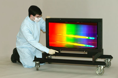
 A very large reflecting diffraction grating.
In optics, a diffraction grating is an optical component with a periodic structure, which splits and diffracts light into several beams travelling in different directions. The directions of these beams depend on the spacing of the grating and the wavelength of the light so that the grating acts as the dispersive element. Because of this, gratings are commonly used in monochromators and spectrometers.
A photographic slide with a fine pattern of purple lines forms a complex grating. For practical applications, gratings generally have ridges or rulings on their surface rather than dark lines. Such gratings can be either transmissive or reflective. Gratings which modulate the phase rather than the amplitude of the incident light are also produced, frequently using holography.
The principles of diffraction gratings were discovered by James Gregory, about a year after Newton's prism experiments, initially with artifacts such as bird feathers. The first man-made diffraction grating was made around 1785 by Philadelphia inventor David Rittenhouse, who strung hairs between two finely threaded screws. This was similar to notable German physicist Joseph von Fraunhofer's wire diffraction grating in 1821.
Contents
Theory of operation
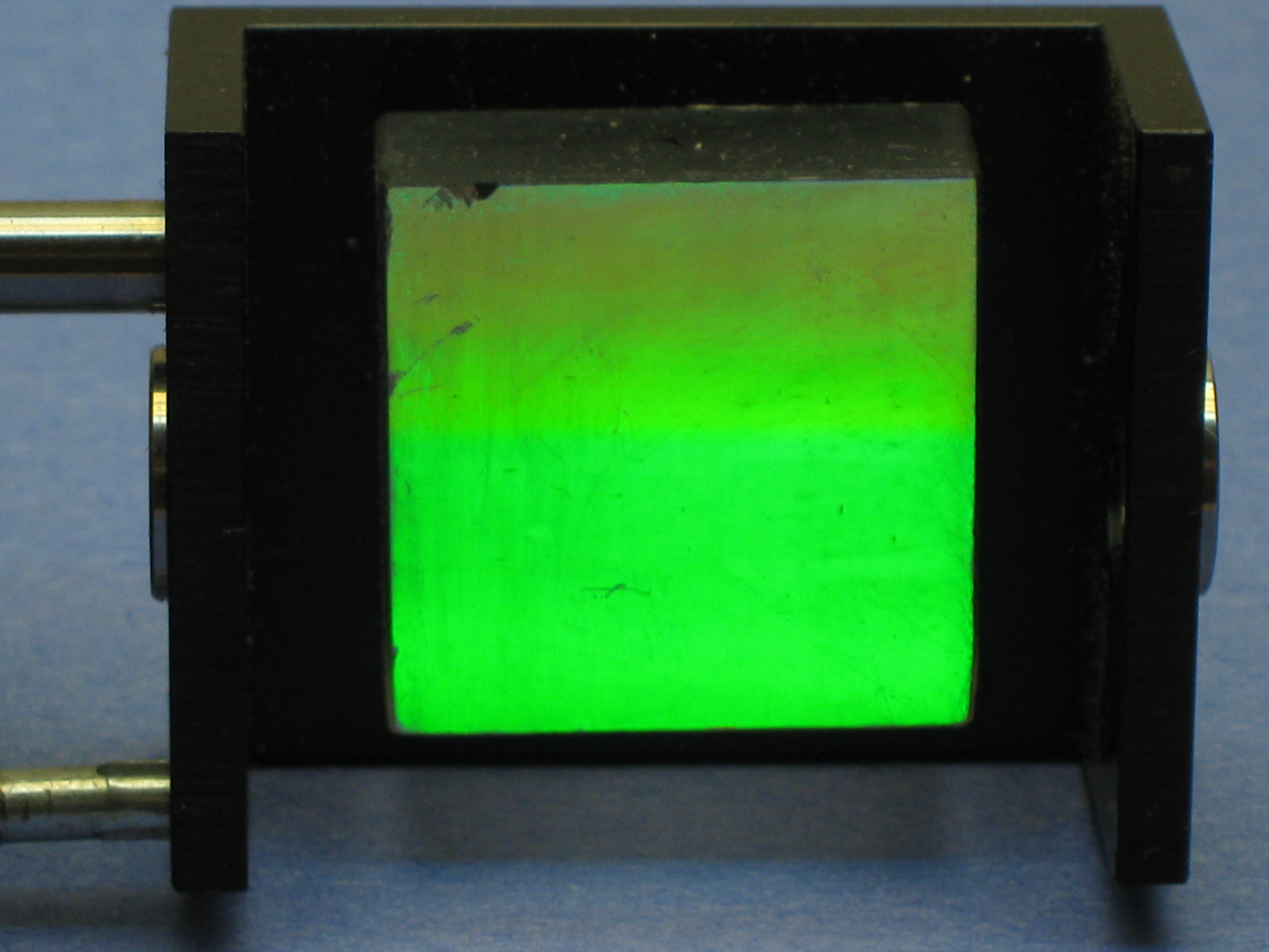
Main article: Diffraction A diffraction grating reflecting green light from a dye laser.
The relationship between the grating spacing and the angles of the incident and diffracted beams of light is known as the grating equation.
According to the Huygens–Fresnel principle, each point on the wavefront of a propagating wave can be considered to act as a point source, and the wavefront at any subsequent point can be found by adding together the contributions from each of these individual point sources.
An idealised grating is considered here which is made up of a set of long and infinitely narrow slits of spacing d. When a plane wave of wavelength λ is incident normally on the grating, each slit in the grating acts as a point source propagating in all directions. The light in a particular direction, θ, is made up of the interfering components from each slit. Generally, the phases of the waves from different slits will vary from one another, and will cancel one another out partially or wholly. However, when the path difference between the light from adjacent slits is equal to the wavelength, λ, the waves will all be in phase. This occurs at angles θm which satisfy the relationship dsinθm/λ=|m| where d is the separation of the slits and m is an integer. Thus, the diffracted light will have maxima at angles θm given by
It is straightforward to show that if a plane wave is incident at an angle θi, the grating equation becomes
The light that corresponds to direct transmission (or specular reflection in the case of a reflection grating) is called the zero order, and is denoted m = 0. The other maxima occur at angles which are represented by non-zero integers m. Note that m can be positive or negative, resulting in diffracted orders on both sides of the zero order beam.
This derivation of the grating equation has used an idealised grating. However, the relationship between the angles of the diffracted beams, the grating spacing and the wavelength of the light apply to any regular structure of the same spacing, because the phase relationship between light scattered from adjacent elements of the grating remains the same. The detailed distribution of the diffracted light depends on the detailed structure of the grating elements as well as on the number of elements in the grating, but it will always give maxima in the directions given by the grating equation.
Gratings can be made in which various properties of the incident light are modulated in a regular pattern; these include
- transparency (transmission amplitude gratings)
- reflectance (reflection amplitude gratings)
- refractive index (phase gratings)
- direction of optical axis (optical axis gratings)
The grating equation applies in all these cases.
QED
QED (quantum electrodynamics) offers another derivation of the properties of a diffraction grating in terms of photons as particles. QED models photons as following all paths from a source to a final point, each of which has a certain probability amplitude, which can be represented as a vector or complex number (equivalently), or as Richard Feynman simply calls them in his book on QED, "arrows".
For the probability that a certain event will happen, one sums the probability amplitudes for all of the possible ways in which the event can occur, and then takes the square of the length of the result. The probability amplitude of a photon from a monochromatic source, in this case, is modeled as an arrow that spins rapidly until it is "evaluated" when the photon reaches its final point. This spinning is actually dependent on the time at which the photon would have left the monochromatic source, as the probability amplitudes of photons do not "spin" while they are in transit. For example, for the probability that light will reflect off of a mirror, one sets the photon's probability amplitude spinning as it leaves the source, follows it to the mirror, and then to its final point,even for paths that do not involve bouncing off of the mirror at equal angles. One then "evaluates" the probability amplitude at the photon's final point; next, one sums these arrows in a standard vector sum, and squares the length of the result for the probability that this photon will reflect off of the mirror. The times these paths take are what determine the angle of the probability amplitude arrow, as they 'spin' at a constant rate (which is related to the frequency of the photon).
The times of the paths near the classical reflection site of the mirror will be nearly the same, so as a result the probability amplitudes will point in nearly the same direction—thus, they will have a sizable sum. Examining the paths towards the edges of the mirror reveals that the times of nearby paths are quite different from each other, and thus we wind up summing vectors that cancel out quickly. So, there is a higher probability that light will follow a near-classical reflection path than a path further out. However, a diffraction grating can be made out of this mirror, by scraping away areas near the edge of the mirror that usually cancel nearby amplitudes out—but now, since the photons would not reflect from the scraped-off portions, the probability amplitudes which all point, for instance, to the right can have a sizable sum. Thus, this would let light of the right frequency sum to a larger probability amplitude, and as such possess a larger probability of reflecting.
This particular description involves many simplifications: a point source, a "surface" that light can reflect off of (thus neglecting the interactions with electrons) and so forth. However, this approximation is a reasonable one to illustrate a diffraction grating conceptually. Light of a different frequency can also use the same diffraction grating, but with a different final point.[1]
Gratings as dispersive elements
The wavelength dependence in the grating equation shows that the grating separates an incident polychromatic beam into its constituent wavelength components, i.e., it is dispersive. Each wavelength of input beam spectrum is sent into a different direction, producing a rainbow of colors under white light illumination. This is visually similar to the operation of a prism, although the mechanism is very different.
 A light bulb of a flashlight seen through a transmissive grating, showing three diffracted orders. The order m = 0 corresponds to a direct transmission of light through the grating. In the first positive order (m = +1), colors with increasing wavelengths (from blue to red) are diffracted at increasing angles.
The diffracted beams corresponding to consecutive orders may overlap, depending on the spectral content of the incident beam and the grating density. The higher the spectral order, the greater the overlap into the next order.
The grating equation shows that the angles of the diffracted orders only depend on the grooves' period, and not on their shape. By controlling the cross-sectional profile of the grooves, it is possible to concentrate most of the diffracted energy in a particular order for a given wavelength. A triangular profile is commonly used. This technique is called blazing. The incident angle and wavelength for which the diffraction is most efficient are often called blazing angle and blazing wavelength. The efficiency of a grating may also depend on the polarization of the incident light. Gratings are usually designated by their groove density, the number of grooves per unit length, usually expressed in grooves per millimeter (g/mm), also equal to the inverse of the groove period. The groove period must be on the order of the wavelength of interest; the spectral range covered by a grating is dependent on groove spacing and is the same for ruled and holographic gratings with the same grating constant. The maximum wavelength that a grating can diffract is equal to twice the grating period, in which case the incident and diffracted light will be at ninety degrees to the grating normal. To obtain frequency dispersion over a wider frequency one must use a prism. In the optical regime, in which the use of gratings is most common, this corresponds to wavelengths between 100 nm and 10 µm. In that case, the groove density can vary from a few tens of grooves per millimeter, as in echelle gratings, to a few thousands of grooves per millimeter.
When groove spacing is less than half the wavelength of light, the only present order is the m = 0 order. Gratings with such small periodicity are called subwavelength gratings and exhibit special optical properties. Made on an isotropic material the subwavelength gratings give rise to form birefringence, in which the material behaves as if it were birefringent.
Fabrication
Originally, high-resolution gratings were ruled using high-quality ruling engines whose construction was a large undertaking. Henry Joseph Grayson designed a machine to make diffraction gratings, succeeding with one of 120,000 lines to the inch (approx. 47 000 per cm) in 1899. Later, photolithographic techniques allowed gratings to be created from a holographic interference pattern. Holographic gratings have sinusoidal grooves and may not be as efficient as ruled gratings, but are often preferred in monochromators because they lead to much less stray light. A copying technique allows high quality replicas to be made from master gratings of either type, thereby lowering fabrication costs.
Another method for manufacturing diffraction gratings uses a photosensitive gel sandwiched between two substrates. A holographic interference pattern exposes the gel which is later developed. These gratings, called volume phase holography diffraction gratings (or VPH diffraction gratings) have no physical grooves, but instead a periodic modulation of the refractive index within the gel. This removes much of the surface scattering effects typically seen in other types of gratings. These gratings also tend to have higher efficiencies, and allow for the inclusion of complicated patterns into a single grating. In older versions of such gratings, environmental susceptibility was a trade-off, as the gel had to be contained at low temperature and humidity. Typically, the photosensitive substances are sealed between two substrates which make them resistant to humidity, thermal and mechanical stresses. VPH diffraction gratings are not destroyed by accidental touches and are more scratch resistant than typical relief gratings.
Semiconductor technology today is also utilized to etch holographically patterned gratings into robust materials such as fused silica. In this way, low stray-light holography is combined with the high efficiency of deep, etched transmission gratings, and can be incorporated into high volume, low cost semiconductor manufacturing technology.
A new technology for grating insertion into integrated photonic lightwave circuits is digital planar holography (DPH). DPH gratings are generated in computer and fabricated on one or several interfaces of an optical waveguide planar with standard micro-lithography or nano-imprinting methods, compatible with mass-production. Light propagates inside the DPH gratings, confined by the refractive index gradient, which provides longer interaction path and greater flexibility in light steering.
Examples
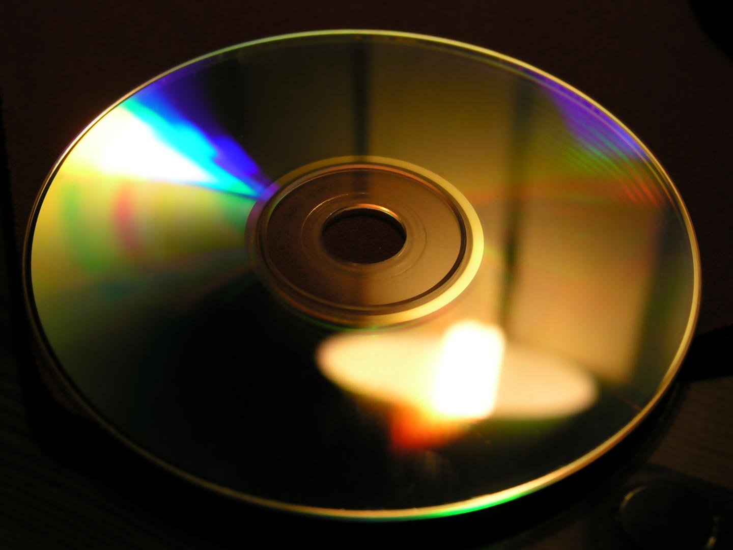
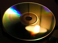 The grooves of a compact disc can act as a grating and produce iridescent reflections.
Diffraction gratings are often used in monochromators, spectrometers, lasers, wavelength division multiplexing devices, optical pulse compressing devices, and many other optical instruments.
Ordinary pressed CD and DVD media are every-day examples of diffraction gratings and can be used to demonstrate the effect by reflecting sunlight off them onto a white wall. This is a side effect of their manufacture, as one surface of a CD has many small pits in the plastic, arranged in a spiral; that surface has a thin layer of metal applied to make the pits more visible. The structure of a DVD is optically similar, although it may have more than one pitted surface, and all pitted surfaces are inside the disc.
In a standard pressed vinyl record when viewed from a low angle perpendicular to the grooves, a similar but less defined effect to that in a CD/DVD is seen. This is due to viewing angle (less than the critical angle of reflection of the black vinyl) and the path of the light being reflected due to this being changed by the grooves, leaving a rainbow relief pattern behind.
Natural gratings
Striated muscle is the most commonly found natural diffraction grating[2] and, indeed, this has helped physiologists in determining the structure of such muscle. Aside from this, diffraction gratings are rarely present in nature. Most commonly confused with diffraction gratings are the iridescent colors of peacock feathers, mother-of-pearl, and butterfly wings. Iridescence is common in birds, fishes, insects, and some flowers, and is almost always caused by thin-film interference rather than diffraction.[3] Diffraction will produce the entire spectrum of colors as the viewing angle changes, whereas thin-film interference usually produces a much narrower range.[4] The cell structures in plants and animals are usually too irregular to produce the fine slit geometry necessary for a diffraction grating.[5] However, natural gratings do occur in some invertebrate marine animals, like the antennae of seed shrimp, and have even been discovered in Burgess Shale fossils.[6][7]
Diffraction grating effects are sometimes seen in meteorology. Diffraction coronas are colorful rings surrounding a source of light, such as the sun. These are usually observed much closer to the light source than halos, and are caused by very fine particles, like water droplets, ice crystals, or smoke particles in a hazy sky. When the particles are all nearly the same size they diffract the incoming light at very specific angles. The exact angle depends on the size of the particles. Diffraction coronas are commonly observed around light sources, like candle flames or street lights, in the fog. Cloud iridescence is caused by diffraction, occurring along coronal rings when the particles in the clouds are all uniform in size.[8]
See also
References
- ^ Feynman, Richard (1985). QED: The Strange Theory of Light and Matter. Princeton, New Jersey: Princeton University Press.
- ^ Baskin et al. LIGHT DIFFRACTION STUDY OF SINGLE SKELETAL MUSCLE FIBERS. BIoPHYs.J.. PMC 1328609. http://www.pubmedcentral.nih.gov/articlerender.fcgi?tool=pmcentrez&artid=1328609.
- ^ Nature's palette: the science of plant color By David Webster Lee - University of Chicago Press 2007 Page 255-256
- ^ Nature's palette: the science of plant color By David Webster Lee - University of Chicago Press 2007 Page 255
- ^ Nature's palette: the science of plant color By David Webster Lee - University of Chicago Press 2007 Page 84
- ^ Nature's palette: the science of plant color By David Webster Lee - University of Chicago Press 2007 Page 41
- ^ http://www.nhm.ac.uk/about-us/news/2006/mar/news_7834.html
- ^ Polarized light in nature By G. P. Können - Cambridge University Press 1985 Page 72-73
 This article incorporates public domain material from the General Services Administration document "Federal Standard 1037C".
- Hutley, Michael, Diffraction Gratings (Techniques of Physics), Academic Press (1982). ISBN 0-12-362980-2
- Loewen, Erwin & Evgeny Popov, Diffraction Gratings and Applications, CRC; 1 edition (1997). ISBN 0-8247-9923-2
- Palmer, Christopher, Diffraction Grating Handbook, 6th edition, Newport Corporation (2005).
- Greenslade, Thomas B., "Wire Diffraction Gratings," The Physics Teacher, February 2004. Volume 42 Issue 2, pp. 76–77.
- Abrahams, Peter, Early Instruments of Astronomical Spectroscopy.
- William E. L. Grossman, "The optical characteristics and production of diffraction gratings," Journal of Chemical Education 70:9 (Sep 1993), p. 741.
- National Optical Astronomy Observatories entry on volume phase holography gratings.
External links
- Diffraction Gratings - The Crucial Dispersive Component
- Diffraction Grating Handbook
- Diffraction Grating Equations
- Automatic calculation of diffraction angles based on input variables.
- Optics Tutorial - Diffraction Gratings Ruled & Holographic
- Ray-Tracing program handling general reflective concave gratings for Windows XP and above
Categories:- Diffraction
- Optical devices
- Photonics


Wikimedia Foundation. 2010.