- Passive differentiator circuit
-
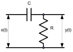
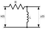
A passive differentiator circuit is a simple four-terminal network consisting of two passive elements as shown in Figures 1 and 2. It is a simple first-order high-pass filter.
Contents
Transfer function
The analysis here is for the capacitive circuit in Figure 1. The inductive case in Figure 2 can be handled in a similar way.
The transfer function shows the dependence of the network gain on the signal frequency for sinusoidal signals.
According to Ohm's law,
where X and Y are input and output signals' amplitudes respectively, and ZR and ZC are the resistor's and capacitor's impedances. Therefore, the complex transfer function is
where
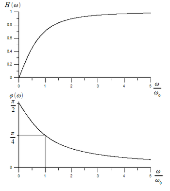
The amplitude transfer function
and the phase transfer function
which are both shown in Figure 3.
Transfer functions for the second circuit are the same (with
 ).
).Impulse response
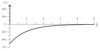
The circuit's impulse response, which is shown in Figure 4, can be derived as an inverse Laplace transform of the complex transfer function:
where
 is a time constant, and δ(t) is a Dirac delta function.
Applications
A passive differentiator circuit is one of the basic electronic circuits, being widely used in circuit analysis based on the equivalent circuit method.
See also
Categories:- Analog circuits
Wikimedia Foundation. 2010.


