- Class diagram
-
UML diagrams Structural UML diagrams Class diagram Component diagram Composite structure diagram Deployment diagram Object diagram Package diagram Profile diagram Behavioural UML diagrams Activity diagram Communication diagram Interaction overview diagram Sequence diagram State diagram Timing diagram Use case diagram In software engineering, a class diagram in the Unified Modeling Language (UML) is a type of static structure diagram that describes the structure of a system by showing the system's classes, their attributes, operations (or methods), and the relationships among the classes.
Contents
Overview
 Hierarchy of UML 2.0 Diagrams, shown as a class diagram. The individual classes are represented just with one compartment, but they often contain up to three compartments.
The class diagram is the main building block of object oriented modelling. It is used both for general conceptual modelling of the systematics of the application, and for detailed modelling translating the models into programming code. Class diagrams can also be used for data modeling.[1] The classes in a class diagram represent both the main objects and or interactions in the application and the objects to be programmed. In the class diagram these classes are represented with boxes which contain three parts: [2]
 A class with three sections.
- The upper part holds the name of the class
- The middle part contains the attributes of the class
- The bottom part gives the methods or operations the class can take or undertake
In the system design of a system, a number of classes are identified and grouped together in a class diagram which helps to determine the static relations between those objects. With detailed modeling, the classes of the conceptual design are often split into a number of subclasses.
In order to further describe the behavior of systems, these class diagrams can be complemented by state diagram or UML state machine. Also instead of class diagrams Object role modeling can be used if you just want to model the classes and their relationships.[2]
Members
UML provides mechanisms to represent class members, such as attributes and methods, and additional information about them.
Visibility
To specify the visibility of a class member (i.e., any attribute or method) there are the following notations that must be placed before the member's name [3]:
+         Public
-         Private
#         Protected
~         Package
/         Derived
underline Static
Scope
The UML specifies two types of scope for members: instance and classifier.[4] Classifier members are commonly recognized as "static" in many programming languages. In the case of instance members, the scope is a specific instance. For attributes, it means that its value can vary between instances. For methods, it means that its invocation affects the instance state, in other words, affects the instance attributes. Otherwise, in the classifier member, the scope is the class. For attributes, it means that its value is equal for all instances. For methods, it means that its invocation does not affect the instance state. To indicate that a member has the classifier scope, its name must be underlined. Otherwise, as default, the instance scope is considered.
Relationships
A relationship is a general term covering the specific types of logical connections found on class and object diagrams. UML shows the following relationships:
Instance Level Relationships
External links
A Link is the basic relationship among objects. It is represented as a line connecting two or more object boxes. It can be shown on an object diagram or class diagram. A link is an instance of an association. In other words, it creates a relationship between two classes.
Association
 Class diagram example of association between two classes
An association represents a family of links. Binary associations (with two ends) are normally represented as a line, with each end connected to a class box. Higher order associations can be drawn with more than two ends. In such cases, the ends are connected to a central diamond.
An association can be named, and the ends of an association can be adorned with role names, ownership indicators, multiplicity, visibility, and other properties.
There are four different types of association: bi-directional, uni-directional, Aggregation (includes Composition aggregation) and Reflexive. Bi-directional and uni-directional associations are the most common ones.
For instance, a flight class is associated with a plane class bi-directionally. Association represents the static relationship shared among the objects of two classes. Example: "department offers courses", is an association relation.Aggregation
 Class diagram showing Aggregation between two classes
Aggregation is a variant of the "has a" or association relationship; aggregation is more specific than association. It is an association that represents a part-whole or part-of relationship. As a type of association, an aggregation can be named and have the same adornments that an association can. However, an aggregation may not involve more than two classes.
Aggregation can occur when a class is a collection or container of other classes, but where the contained classes do not have a strong life cycle dependency on the container—essentially, if the container is destroyed, its contents are not.
In UML, it is graphically represented as a hollow diamond shape on the containing class end of the tree with lines that connect contained classes to the containing class.
Composition (Aggregation)
 Class diagram showing Composition between two classes at top and Aggregation between two classes at bottom
Composition is a stronger variant of the "owns a" or association relationship; composition is more specific than aggregation.
Composition usually has a strong life cycle dependency between instances of the container class and instances of the contained class(es): If the container is destroyed, normally every instance that it contains is destroyed as well. (Note that a part can (where allowed) be removed from a composite before the composite is deleted, and thus not be deleted as part of the composite.)
The UML graphical representation of a composition relationship is a filled diamond shape on the containing class end of the tree of lines that connect contained class(es) to the containing class.
Differences between Composition and Aggregation
When attempting to represent real-world whole-part relationships, e.g., an engine is a part of a car, the composition relationship is most appropriate. However, when representing a software or database relationship, e.g., car model engine ENG01 is part of a car model CM01, an aggregation relationship is best, as the engine, ENG01 may be also part of a different car model. Thus the aggregation relationship is often called "catalog" containment to distinguish it from composition's "physical" containment.
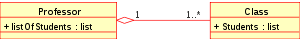
The whole of a composition must have a multiplicity of 0..1 or 1, indicating that a part must belong to only one whole; the part may have any multiplicity. For example, consider University and Department classes. A department belongs to only one university, so University has multiplicity 1 in the relationship. A university can (and will likely) have multiple departments, so Department has multiplicity 1..*.
Class Level Relationships
Generalization
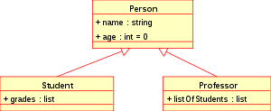 Class diagram showing generalization between one superclass and two subclasses
The Generalization relationship ("is a") indicates that one of the two related classes (the subclass) is considered to be a specialized form of the other (the super type) and superclass is considered as 'Generalization' of subclass. In practice, this means that any instance of the subtype is also an instance of the superclass. An exemplary tree of generalizations of this form is found in binomial nomenclature: human beings are a subclass of simian, which are a subclass of mammal, and so on. The relationship is most easily understood by the phrase 'an A is a B' (a human is a mammal, a mammal is an animal).
The UML graphical representation of a Generalization is a hollow triangle shape on the superclass end of the line (or tree of lines) that connects it to one or more subtypes.
The generalization relationship is also known as the inheritance or "is a" relationship.
The superclass in the generalization relationship is also known as the "parent", superclass, base class, or base type.
The subtype in the specialization relationship is also known as the "child", subclass, derived class, derived type, inheriting class, or inheriting type.
Note that this relationship bears no resemblance to the biological parent/child relationship: the use of these terms is extremely common, but can be misleading.
- Generalization-Specialization relationship
- A is a type of B
- E. g. "an oak is a type of tree", "an automobile is a type of vehicle"
Generalization can only be shown on class diagrams and on Use case diagrams.
Realization
In UML modeling, a realization relationship is a relationship between two model elements, in which one model element (the client) realizes (implements or executes) the behavior that the other model element (the supplier) specifies. A realization is indicated by a dashed line with an unfilled arrowhead towards the supplier.
Realizations can only be shown on class or component diagrams.
A realization is a relationship between classes, interfaces, components, and packages that connects a client element with a supplier element. A realization relationship between classes and interfaces and between components and interfaces shows that the class realizes the operations offered by the interface.
General Relationship
 Class diagram showing dependency between "Car" class and "Wheel" class (Even more clear example would be "Car Dependency on gas", because Car already aggregates (and not just use) wheels)
Dependency
Dependency is a weaker form of relationship which indicates that one class depends on another because it uses it at some point of time. One class depends on another if the latter is a parameter variable or local variable of a method of the former. This is different from an association, where an attribute of the former is an instance of the latter.
Multiplicity
The association relationship indicates that (at least) one of the two related classes makes reference to the other. In contrast with the generalization relationship, this is most easily understood through the phrase 'A has a B' (a mother cat has kittens, kittens have a mother cat).
The UML representation of an association is a line with an optional arrowhead indicating the role of the object(s) in the relationship, and an optional notation at each end indicating the multiplicity of instances of that entity (the number of objects that participate in the association).
0..1 No instances, or one instance (optional, may) 1 Exactly one instance 0..* or * Zero or more instances 1..* One or more instances (at least one) Analysis Stereotypes
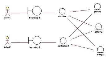
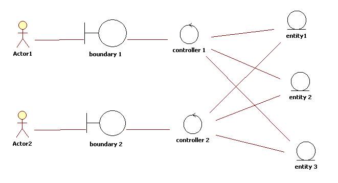
In the early stages of a project's technical analysis, class diagrams can be used to produce early conceptual models of the system. Classes at this stage often take the form of boundaries, controls and entities and rarely survive into the design without heavy changes.
Boundaries
Boundary classes handle the communication between actors and the system's internal components. They might be user interfaces, system interfaces or device interfaces (for example). They are identified by each actor–use-case pair on the system's use-case diagram, with one and only one boundary class existing for each pair.
They are drawn as circles with a short line to the left attached to a vertical line the same height as the circle (as though it is attached to the side of the use-case system boundary). Alternatively, they can be drawn as normal classes with the «boundary» stereotype notation above the class name.
Entities
Entity classes model the information handled by the system, and sometimes the behaviour associated with the information. They should not be identified as database tables or other data-stores.
They are drawn as circles with a short line attached to the bottom of the circle. Alternatively, they can be drawn as normal classes with the «entity» stereotype notation above the class name
Controls
Control classes handle the flow of control for a use-case and can therefore be seen as co-ordinating representation classes. These do not do everything in the use case, but co-ordinate with other classes that can do the work for them.
See also
- Related diagrams
References
- ^ Sparks, Geoffrey. "Database Modelling in UML". http://www.methodsandtools.com/archive/archive.php?id=9. Retrieved 8 September 2011.
- ^ a b Scott W. Ambler (2009) UML 2 Class Diagrams. Webdoc 2003-2009. Accessed Dec 2, 2009
- ^ Holub Associates: UML Reference Card, Version 2.1.2: August 2007. Retrieved 12 March 2011.
- ^ OMG Unified Modeling Language (OMG UML) Superstructure, Version 2.3: May 2010. Retrieved 23 September 2010.
External links
- Introduction to UML 2 Class Diagrams
- UML 2 Class Diagram Guidelines
- IBM Class diagram Introduction
- OMG UML 2.2 specification documents
- UML 2 Class Diagrams
Unified Modeling Language Actors Organizations: Object Management Group • UML Partners Persons: Grady Booch • Ivar Jacobson • James Rumbaugh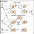

Concepts Object oriented: Object-oriented programming • Object-oriented analysis and design
Structure: Actor • Attribute • Artifact • Class • Component • Interface • Object • Package • Profile diagram
Behavior: Activity • Event • Message • Method • State • Use case
Relationships: Aggregation • Association • Composition • Dependency • Generalization (or Inheritance)
Extensibility: Profile • Stereotype
Other concepts: MultiplicityDiagrams StructuralClass diagram • Component diagram • Composite structure diagram • Deployment diagram • Object diagram • Package diagramBehaviourActivity diagram • State Machine diagram • Use case diagramInteractionDerived languages Systems Modeling Language (SysML) • UML eXchange Format (UXF) • XML Metadata Interchange (XMI)Other topics Categories:- UML diagrams


Wikimedia Foundation. 2010.