- Component diagram
-
UML diagrams Structural UML diagrams Class diagram Component diagram Composite structure diagram Deployment diagram Object diagram Package diagram Profile diagram Behavioural UML diagrams Activity diagram Communication diagram Interaction overview diagram Sequence diagram State diagram Timing diagram Use case diagram In the Unified Modeling Language, a component diagram depicts how components are wired together to form larger components and or software systems. They are used to illustrate the structure of arbitrarily complex systems.
Overview
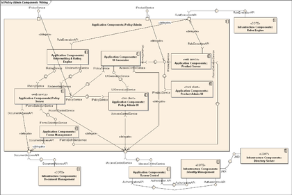
Components are wired together by using an assembly connector to connect the required interface of one component with the provided interface of another component. This illustrates the service consumer - service provider relationship between the two components.
An assembly connector is a "connector between two components that defines that one component provides the services that another component requires. An assembly connector is a connector that is defined from a required interface or port to a provided interface or port."[1]
When using a component diagram to show the internal structure of a component, the provided and required interfaces of the encompassing component can delegate to the corresponding interfaces of the contained components.
A delegation connector is a "connector that links the external contract of a component (as specified by its ports) to the internal realization of that behavior by the component’s parts."[1]
The example above illustrates what a typical Insurance policy administration system might look like. Each of the components depicted in the above diagram may have other component diagrams illustrating their internal structure.
References
External links
- Introduction to UML 2 Component Diagrams by Scott W. Ambler
- UML 2 Component Diagram Guidelines by Scott W. Ambler
- Component Diagrams in UML 2
- UML 2 Component Diagrams
Unified Modeling Language Actors Organizations: Object Management Group • UML Partners Persons: Grady Booch • Ivar Jacobson • James Rumbaugh


Concepts Object oriented: Object-oriented programming • Object-oriented analysis and design
Structure: Actor • Attribute • Artifact • Class • Component • Interface • Object • Package • Profile diagram
Behavior: Activity • Event • Message • Method • State • Use case
Relationships: Aggregation • Association • Composition • Dependency • Generalization (or Inheritance)
Extensibility: Profile • Stereotype
Other concepts: MultiplicityDiagrams StructuralClass diagram • Component diagram • Composite structure diagram • Deployment diagram • Object diagram • Package diagramBehaviourActivity diagram • State Machine diagram • Use case diagramInteractionDerived languages Systems Modeling Language (SysML) • UML eXchange Format (UXF) • XML Metadata Interchange (XMI)Other topics Categories:- UML diagrams
- Component-based software engineering
- Unified Modeling Language stubs
Wikimedia Foundation. 2010.

