- Deployment diagram
-
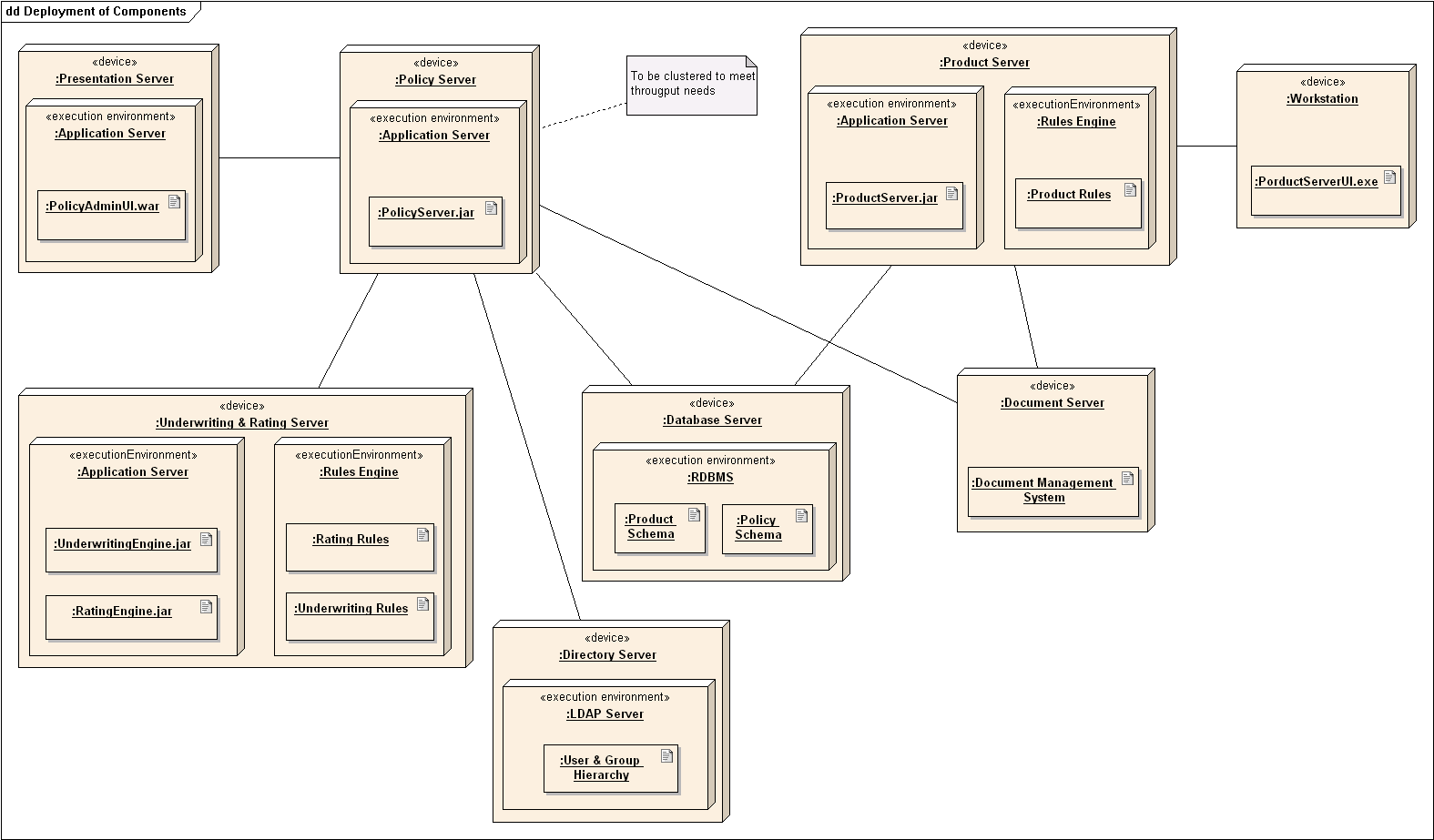
 A sample deployment diagram
UML diagrams Structural UML diagrams Class diagram Component diagram Composite structure diagram Deployment diagram Object diagram Package diagram Profile diagram Behavioural UML diagrams Activity diagram Communication diagram Interaction overview diagram Sequence diagram State diagram Timing diagram Use case diagram A deployment diagram in the Unified Modeling Language models the physical deployment of artifacts on nodes.[1] To describe a web site, for example, a deployment diagram would show what hardware components ("nodes") exist (e.g., a web server, an application server, and a database server), what software components ("artifacts") run on each node (e.g., web application, database), and how the different pieces are connected (e.g. JDBC, REST, RMI).
The nodes appear as boxes, and the artifacts allocated to each node appear as rectangles within the boxes. Nodes may have subnodes, which appear as nested boxes. A single node in a deployment diagram may conceptually represent multiple physical nodes, such as a cluster of database servers.
There are two types of Nodes .
- Device Node
- Execution Environment Node
Device nodes are physically computing resources with processing memory and services to execute software,such as typical computer or mobile phones. EEN node is software computing resource that runs within an outer node and which itself provides a service to host and execute other executable software elements.
References
- ^ Deployment diagrams show "the allocation of Artifacts to Nodes according to the Deployments defined between them." Unified Modeling Language, Superstructure, V2.1.2 p. 202.
External links
- Introduction to UML 2 Deployment Diagrams by Scott W. Ambler
- UML 2 Deployment Diagram
- UML Deployment Diagrams
Unified Modeling Language Actors Organizations: Object Management Group • UML Partners Persons: Grady Booch • Ivar Jacobson • James Rumbaugh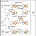

Concepts Object oriented: Object-oriented programming • Object-oriented analysis and design
Structure: Actor • Attribute • Artifact • Class • Component • Interface • Object • Package • Profile diagram
Behavior: Activity • Event • Message • Method • State • Use case
Relationships: Aggregation • Association • Composition • Dependency • Generalization (or Inheritance)
Extensibility: Profile • Stereotype
Other concepts: MultiplicityDiagrams StructuralClass diagram • Component diagram • Composite structure diagram • Deployment diagram • Object diagram • Package diagramBehaviourActivity diagram • State Machine diagram • Use case diagramInteractionDerived languages Systems Modeling Language (SysML) • UML eXchange Format (UXF) • XML Metadata Interchange (XMI)Other topics Categories:- UML diagrams
- Unified Modeling Language stubs


Wikimedia Foundation. 2010.