- Entity-relationship model
-
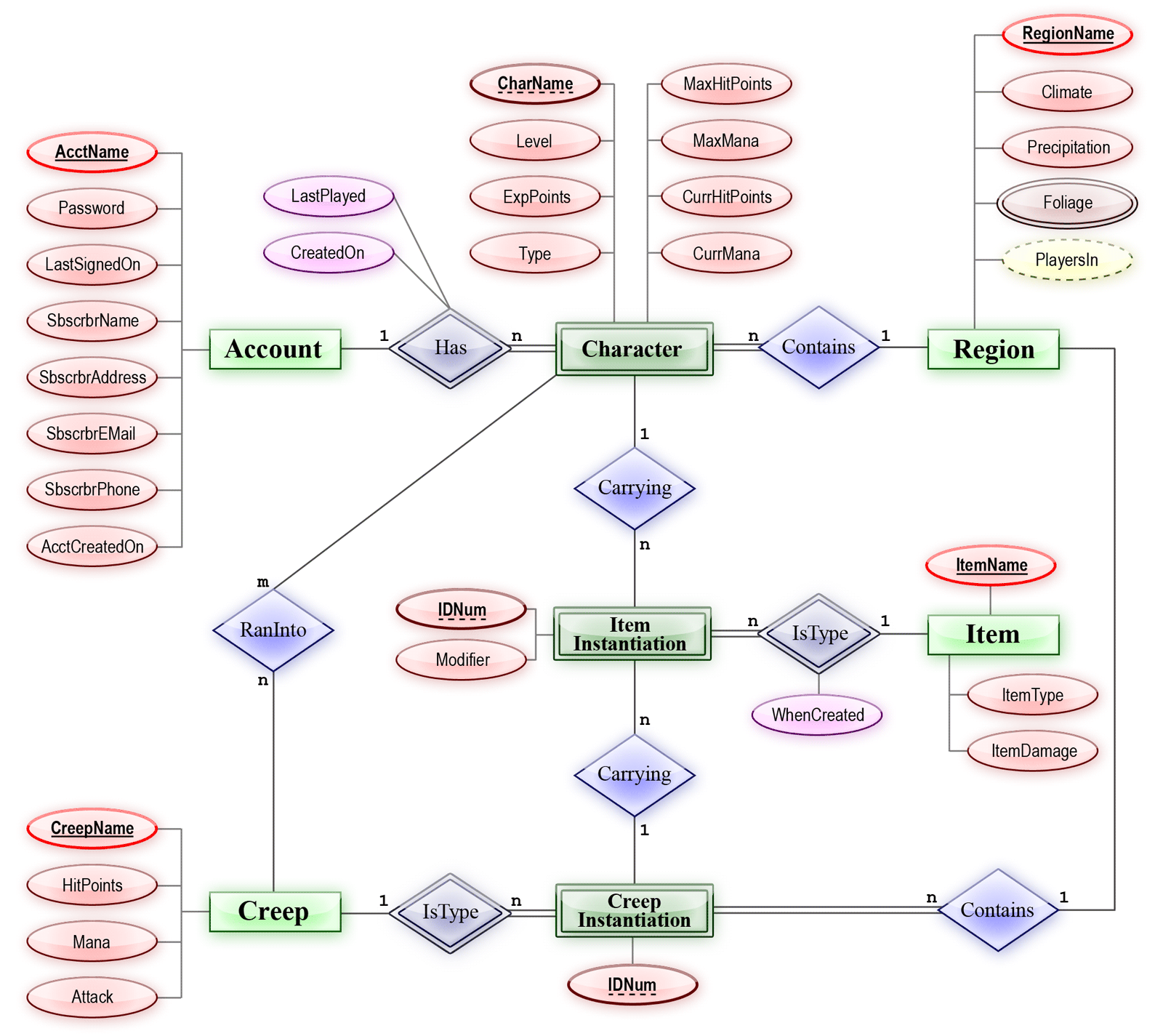
 A sample Entity-relationship diagram using Chen's notation
In software engineering, an entity-relationship model (ERM) is an abstract and conceptual representation of data. Entity-relationship modeling is a database modeling method, used to produce a type of conceptual schema or semantic data model of a system, often a relational database, and its requirements in a top-down fashion. Diagrams created by this process are called entity-relationship diagrams, ER diagrams, or ERDs.
This article refers to the techniques proposed in Peter Chen's 1976 paper.[1] However, variants of the idea existed previously,[2] and have been devised subsequently.
Contents
Overview
The first stage of information system design uses these models during the requirements analysis to describe information needs or the type of information that is to be stored in a database. The data modeling technique can be used to describe any ontology (i.e. an overview and classifications of used terms and their relationships) for a certain area of interest. In the case of the design of an information system that is based on a database, the conceptual data model is, at a later stage (usually called logical design), mapped to a logical data model, such as the relational model; this in turn is mapped to a physical model during physical design. Note that sometimes, both of these phases are referred to as "physical design".
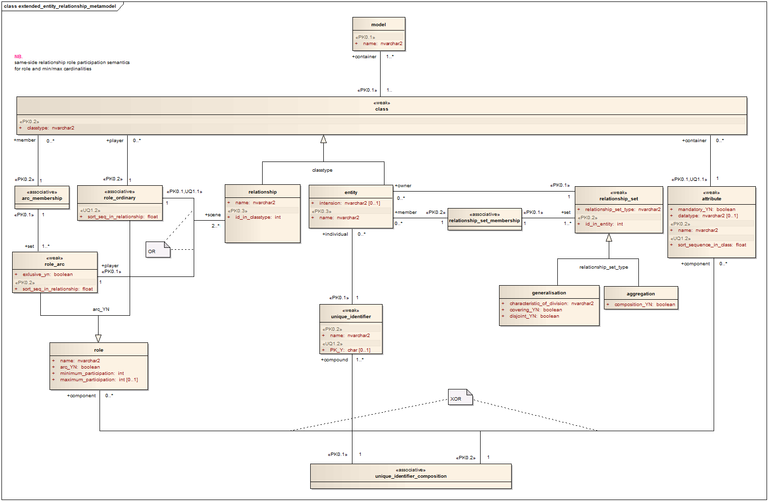
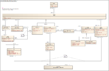 A UML metamodel of Extended Entity Relationship models
The building blocks: entities, relationships, and attributes
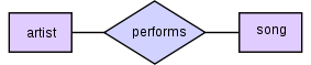 Two related entities
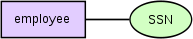 An entity with an attribute
 A relationship with an attribute
 Primary key
An entity may be defined as a thing which is recognized as being capable of an independent existence and which can be uniquely identified. An entity is an abstraction from the complexities of some domain. When we speak of an entity we normally speak of some aspect of the real world which can be distinguished from other aspects of the real world.[3]
An entity may be a physical object such as a house or a car, an event such as a house sale or a car service, or a concept such as a customer transaction or order. Although the term entity is the one most commonly used, following Chen we should really distinguish between an entity and an entity-type. An entity-type is a category. An entity, strictly speaking, is an instance of a given entity-type. There are usually many instances of an entity-type. Because the term entity-type is somewhat cumbersome, most people tend to use the term entity as a synonym for this term.
Entities can be thought of as nouns. Examples: a computer, an employee, a song, a mathematical theorem.
A relationship captures how two or more entities are related to one another. Relationships can be thought of as verbs, linking two or more nouns. Examples: an owns relationship between a company and a computer, a supervises relationship between an employee and a department, a performs relationship between an artist and a song, a proved relationship between a mathematician and a theorem.
The model's linguistic aspect described above is utilized in the declarative database query language ERROL, which mimics natural language constructs. ERROL's semantics and implementation are based on Reshaped relational algebra (RRA), a relational algebra which is adapted to the ERM and captures its linguistic aspect.
Entities and relationships can both have attributes. Examples: an employee entity might have a Social Security Number (SSN) attribute; the proved relationship may have a date attribute.
Every entity (unless it is a weak entity) must have a minimal set of uniquely identifying attributes, which is called the entity's primary key.
Entity-relationship diagrams don't show single entities or single instances of relations. Rather, they show entity sets and relationship sets. Example: a particular song is an entity. The collection of all songs in a database is an entity set. The eaten relationship between a child and her lunch is a single relationship. The set of all such child-lunch relationships in a database is a relationship set. In other words, a relationship set corresponds to a relation in mathematics, while a relationship corresponds to a member of the relation.
Certain cardinality constraints on relationship sets may be indicated as well.
Relationships, roles and cardinalities
In Chen's original paper he gives an example of a relationship and its roles. He describes a relationship "marriage" and its two roles "husband" and "wife".
A person plays the role of husband in a marriage (relationship) and another person plays the role of wife in the (same) marriage. These words are nouns. That is no surprise, naming things requires a noun.
However as is quite usual with new ideas, many eagerly appropriated the new terminology but then applied it to their own old ideas. Thus the lines, arrows and crows-feet of their diagrams owed more to the earlier Bachman diagrams than to Chen's relationship diamonds. And they similarly misunderstood other important concepts.
In particular, it became fashionable (now almost to the point of exclusivity) to "name" relationships and roles as verbs or phrases.
Relationship Names
A relationship expressed with a verb that implies direction, makes it impossible to discuss the model using correct English. Examples are:
- the song and the performer are related by a 'performs'
- the husband and wife are related by an 'is-married-to'.
Expressing the relationships with a noun resolves this:
- the song and the performer are related by a 'performance'
- the husband and wife are related by a 'marriage'.
Role naming
It has also become prevalent to name roles with phrases e.g. is-the-owner-of and is-owned-by etc. Correct nouns in this case are "owner" and "possession". Thus "person plays the role of owner" and "car plays the role of possession" rather than "person plays the role of is-the-owner-of" etc.
The use of nouns has direct benefit when generating physical implementations from semantic models. When a person has two relationships with car then it is possible to very simply generate names such as "owner_person" and "driver_person" which are immediately meaningful.
Cardinalities
However some modifications to the original specification are beneficial. Chen described look-across cardinalities. UML perpetuates this. (As an aside, the Barker-Ellis notation used in Oracle Designer, uses same-side for minimum cardinality (analogous to optionality) and role, but look-across for maximum cardinality (the crows foot)).
Other authors (Merise,[4] Elmasri & Navathe [5] amongst others[6]) prefer same-side for roles and both minimum and maximum cardinalities. Recent researchers (Feinerer,[7] Dullea et. alia [8]) have shown that this is more coherent when applied to n-ary relationships of order >2.
In Dullea et. alia "An analysis of structural validity in entity-relationship modeling" one reads "A 'look across' notation such as used in the UML does not effectively represent the semantics of participation constraints imposed on relationships where the degree is higher than binary."
In Feinerer it says "Problems arise if we operate under the look-across semantics as used for UML associations. Hartmann [9] investigates this situation and shows how and why different transformations fail." (Although the "reduction" mentioned is spurious as the two diagrams 3.4 and 3.5 are in fact the same) and also "As we will see on the next few pages, the look-across interpretation introduces several difficulties which prevent the extension of simple mechanisms from binary to n-ary associations."
Semantic Modelling
The father of ER modelling said in his seminal paper: "The entity-relationship model adopts the more natural view that the real world consists of entities and relationships. It incorporates some of the important semantic information about the real world." [10] He is here in accord with philosophic and theoretical traditions from the time of the Ancient Greek philosophers: Socrates, Plato and Aristotle (428 BC) through to modern epistemology, semiotics and logic of Pierce, Frege and Russell. Plato himself associates knowledge with the apprehension of unchanging Forms (The forms, according to Socrates, are roughly speaking archetypes or abstract representations of the many types of things, and properties) and their relationships to one another. In his original 1976 article Chen explicitly contrasts Entity-Relationship diagrams with record modelling techniques: "The data structure diagram is a representation of the organisation of records and is not an exact representation of entities and relationships." Several other authors also support his program:
Kent in "Data and Reality" : "One thing we ought to have clear in our minds at the outset of a modelling endeavour is whether we are intent on describing a portion of "reality" (some human enterprise) or a data processing activity."
Abrial in "Data Semantics" : "... the so called "logical" definition and manipulation of data are still influenced (sometimes unconsciously) by the "physical" storage and retrieval mechanisms currently available on computer systems."
Stamper: "They pretend to describe entity types, but the vocabulary is from data processing: fields, data items, values. Naming rules don't reflect the conventions we use for naming people and things; they reflect instead techniques for locating records in files."
In Jackson's words: "The developer begins by creating a model of the reality with which the system is concerned, the reality which furnishes its [the system's] subject matter ..."
Elmasri, Navathe: "The ER model concepts are designed to be closer to the user’s perception of data and are not meant to describe the way in which data will be stored in the computer."
A semantic model is a model of concepts, it is sometimes called a "platform independent model". It is an intensional model. At the latest since Carnap, it is well known that:[11] "...the full meaning of a concept is constituted by two aspects, its intension and its extension. The first part comprises the embedding of a concept in the world of concepts as a whole, i.e. the totality of all relations to other concepts. The second part establishes the referential meaning of the concept, i.e. its counterpart in the real or in a possible world". An extensional model is that which maps to the elements of a particular methodology or technology, and is thus a "platform specific model". The UML specification explicitly states that associations in class models are extensional and this is in fact self evident by considering the extensive array of additional "adornments" provided by the specification over and above those provided by any of the prior candidate "semantic modelling languages"."UML as a Data Modeling Notation, Part 2"
Diagramming conventions
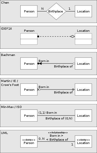 Various methods of representing the same one to many relationship. In each case, the diagram shows the relationship between a person and a place of birth: each person must have been born at one, and only one, location, but each location may have had zero or more people born at it.
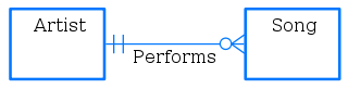 Two related entities shown using Crow's Foot notation. In this example, an optional relationship is shown between Artist and Song; the symbols closest to the song entity represents "zero, one, or many", whereas a song has "one and only one" Artist. The former is therefore read as, an Artist (can) perform(s) "zero, one, or many" song(s).
Chen's notation for entity-relationship modeling uses rectangles to represent entities, and diamonds to represent relationships appropriate for first-class objects: they can have attributes and relationships of their own. Entity sets are drawn as rectangles, relationship sets as diamonds. If an entity set participates in a relationship set, they are connected with a line.
Attributes are drawn as ovals and are connected with a line to exactly one entity or relationship set.
Cardinality constraints are expressed as follows:
- a double line indicates a participation constraint, totality or surjectivity: all entities in the entity set must participate in at least one relationship in the relationship set;
- an arrow from entity set to relationship set indicates a key constraint, i.e. injectivity: each entity of the entity set can participate in at most one relationship in the relationship set;
- a thick line indicates both, i.e. bijectivity: each entity in the entity set is involved in exactly one relationship.
- an underlined name of an attribute indicates that it is a key: two different entities or relationships with this attribute always have different values for this attribute.
Attributes are often omitted as they can clutter up a diagram; other diagram techniques often list entity attributes within the rectangles drawn for entity sets.
Related diagramming convention techniques:
- Bachman notation
- EXPRESS
- IDEF1X[12]
- Martin notation
- (min, max)-notation of Jean-Raymond Abrial in 1974
- UML class diagrams
- Merise
Crow's Foot Notation
Crow's Foot notation is used in Barker's Notation, SSADM and Information Engineering. Crow's Foot diagrams represent entities as boxes, and relationships as lines between the boxes. Different shapes at the ends of these lines represent the cardinality of the relationship.
Crow's Foot notation was used in the 1980s by the consultancy practice CACI. Many of the consultants at CACI (including Richard Barker) subsequently moved to Oracle UK, where they developed the early versions of Oracle's CASE tools, introducing the notation to a wider audience. The following tools use Crow's Foot notation: ARIS, System Architect, Visio, PowerDesigner, Toad Data Modeler, DeZign for Databases, Devgems Data Modeler, OmniGraffle, MySQL Workbench and SQL Developer Data Modeler. CA's ICASE tool, CA Gen aka Information Engineering Facility also uses this notation.
ER diagramming tools
There are many ER diagramming tools. Some free software ER diagramming tools that can interpret and generate ER models and SQL and do database analysis are MySQL Workbench (formerly DBDesigner), and Open ModelSphere (open-source). A freeware ER tool that can generate database and application layer code (webservices) is the RISE Editor.
Some of the proprietary ER diagramming tools are Avolution, dbForge Studio for MySQL, ER/Studio, ERwin, MEGA International, ModelRight, OmniGraffle, Oracle Designer, PowerDesigner, Rational Rose, Sparx Enterprise Architect, SQLyog, System Architect, Toad Data Modeler, and Visual Paradigm.
Some free software diagram tools just draw the shapes without having any knowledge of what they mean, nor do they generate SQL. These include yEd, LucidChart, Kivio, and Dia.
See also
- Associative entity
- Database design
- Data structure diagram
- Enhanced Entity-Relationship Model
- Object Role Modeling
- Three schema approach
- Value range structure diagrams
- Comparison of Data Modeling Tools
References
- ^ "The Entity Relationship Model: Toward a Unified View of Data" for entity-relationship modeling.
- ^ A.P.G. Brown, "Modelling a Real-World System and Designing a Schema to Represent It", in Douque and Nijssen (eds.), Data Base Description, North-Holland, 1975, ISBN 0-7204-2833-5.
- ^ Paul Beynon-Davies (2004). Database Systems. Houndmills, Basingstoke, UK: Palgrave
- ^ Hubert Tardieu, Arnold Rochfeld and René Colletti La methode MERISE: Principes et outils (Paperback - 1983)
- ^ Elmasri, Ramez, B. Shamkant, Navathe, Fundamentals of Database Systems, third ed., Addison-Wesley, Menlo Park, CA, USA, 2000.
- ^ ER 2004 : 23rd International Conference on Conceptual Modeling, Shanghai, China, November 8-12, 2004
- ^ A Formal Treatment of UML Class Diagrams as an Efficient Method for Configuration Management 2007
- ^ James Dullea, Il-Yeol Song, Ioanna Lamprou - An analysis of structural validity in entity-relationship modeling 2002
- ^ "Reasoning about participation constraints and Chen's constraints" S Hartmann - 2003
- ^ "The Entity-Relationship Model-Toward a Unified View of Data"
- ^ http://wenku.baidu.com/view/8048e7bb1a37f111f1855b22.html
- ^ IDEF1X[dead link]
Further reading
- Richard Barker (1990). CASE Method: Tasks and Deliverables. Wokingham, England: Addison-Wesley.
- Paul Beynon-Davies (2004). Database Systems. Houndmills, Basingstoke, UK: Palgrave
- Peter Chen, Peter Pin-Shan (March 1976). "The Entity-Relationship Model - Toward a Unified View of Data". ACM Transactions on Database Systems 1 (1): 9–36. doi:10.1145/320434.320440.
- 1976. "The Entity-Relationship Model--Toward a Unified View of Data". In: ACM Transactions on Database Systems 1/1/1976 ACM-Press ISSN 0362-5915, S. 9–36
External links
- Entity Relationship Modeling - Article from Development Cycles
- Entity Relationship Modelling
- An Entity Relationship Diagram Example. Demonstrates the crow's feet notation by way of an example.
- "Entity-Relationship Modeling: Historical Events, Future Trends, and Lessons Learned" by Peter Chen.
- "English, Chinese and ER diagrams" by Peter Chen.
- Case study: E-R diagram for Acme Fashion Supplies by Mark H. Ridley.
- Logical Data Structures (LDSs) - Getting started by Tony Drewry.
- Introduction to Data Modeling
- Lecture by Prof.Dr.Muhittin GÖKMEN, Department of Computer Engineering, Istanbul Technical University.
- ER-Diagram Convention
- Crow's Foot Notation
- "Articulated Entity Relationship (AER) Diagram for Complete Automation of Relational Database Normalization" P. S. Dhabe, Dr. M. S. Patwardhan, Asavari A. Deshpande.
Categories:- Data modeling diagrams
- Data modeling
- Data modeling languages


Wikimedia Foundation. 2010.