- Oil well control
-
Oil well control is the management of the dangerous effects caused by unexpected high pressures upon surface equipment of oil or gas drilling rigs. Technically, oil well control involves preventing Formation fluid, usually referred to as kick, from entering into the Wellbore during drilling. Formation fluid can enter the wellbore if the pressure exerted by the column of drilling fluid is not great enough to overcome the pressure exerted by the fluids in the formation being drilled.[1][2] Oil well control also includes monitoring a well for signs of impending influx of formation fluid into the wellbore during drilling, and procedures to stop the well from flowing when it happens by taking proper remedial actions.[3] Failure to manage and control these pressure effects can cause serious equipment damage and injury/loss of life. Well control situations that are improperly managed cause blowouts, which are the uncontrolled and explosive expulsion of formation fluid from the well, usually resulting in a fire.[4]
Oil well control requires proper understanding of the various pressures that come to play during oil well drilling and also understanding kick concept, when it may occur, and how to prevent it from developing into a blowout.
Importance of Oil well control
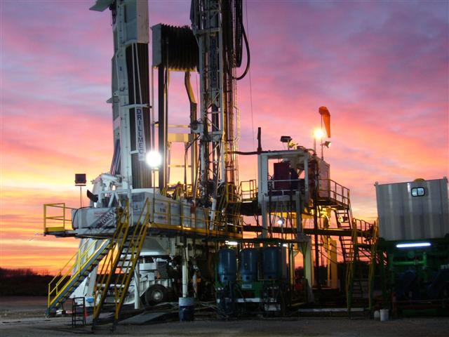
 Modern driller Argentina.
Oil Well control is one of the most important aspects of drilling operations. Improper handling of kicks in oil well control can result in blowouts with very grave consequences, including the loss of valuable resources. Even though the cost of a blowout (as a result of improper/no oil well control) can easily reach several millions of USdollars, the monetary loss is not as serious as the other damages that can occur: irreparable damage to the environment, waste of valuable resources, ruined equipment, and most importantly, the safety and lives of personnel on the drilling rig.[5][6]
In other to avert these terrible consequences of blowout, the utmost attention must be given to oil well control. Therefore oil well control procedures should not start when abnormal situation is noticed in the wellbore. Instead, oil well control should start immediately, the moment a new rig position is sited. This will mean from the time the new location is picked, all drilling, completion, workover, snubbing and all other related drilling related operations should be done with proper oil well control in mind.[7] This will involve widespread training of personnel, the development of strict operational guidelines and the design of drilling programs from the standpoint of maximizing the probability of successfully regaining hydrostatic control of a well after a significant influx of formation fluid has taken place.[8][9]
Fundamental concepts and terminology
Pressure is a very important concept in the oil and gas industry. It can be defined as the force exerted per unit area. Its SI unit is newtons per square metre or pascal. Another unit, bar, is also widely used as a measure of pressure, with 1 bar equal to 100 kilopascals. Normally pressure is measured in the petroleum industry in units of pounds force per square inch of area or psi. 1 psi equals 6894.76 pascals.
Hydrostatic pressure
Hydrostatic pressure(HSP) can be defined as pressure due to a column of fluid that is not moving. That is, a column of fluid that is static or at rest exerts pressure due to local force of gravity on the column of the fluid.[10]
The formula for calculating hydrostatic pressure in SI units is:
Hydrostatic pressure = Height (m) × Density (kg/m³) × Gravity (m/s²).[11]
All fluids in a wellbore exert hydrostatic pressure, which is a function of density and vertical height of the fluid column. In US oil field units, hydrostatic pressure can be expressed as:
HSP = 0.052 × MV × TVD, where MV ( Mud Weight or density) is the drilling fluid density in pounds per gallon ppg, TVD is the true vertical depth in feet and HSP is the hydrostatic pressure in psi. The 0.052 is needed as the conversion factor to psi unit of HSP.[12][13]
To convert these units to SI units, one can use:
- 1 ppg = ≈ 119.8264273 kg/m³
- 1 ft = 0.3048 metres
- 1 psi = 0.0689475729 bar
- 1 bar = 105 pascals
Pressure gradient
Pressure gradient is described as the pressure per unit length. Often in oil well control pressure exerted by fluid is expressed in terms of its pressure gradient. The SI unit is pascal/metres. Hydrostatic pressure gradient can be written as:
Pressure gradient (psi/ft) = HSP/TVD = 0.052 × MV (ppg).[14]
Formation pressure
Formation pressure is the pressure exerted by the formation fluids which are the liquids and gases contained in the geologic formations encountered while drilling for oil or gas.It can also be said to be the pressure contained within the pores of the formation or reservoir being drilled. Formation pressure is as a result of the hydrostatic pressure of the formation fluids above the depth of interest together with pressure trapped in the formation. Under formation pressure we can have:
- Normally pressured formation
- Abnormal formation pressure
- Subnormal formation pressure
- Normally pressured formation
Normally pressured formation has a formation pressure that is the same with the hydrostatic pressure of the fluids above it.As the fluids above the formation is usually some form of water, we can define this pressure as the pressure exerted by a column of water from the formation's depth to sea level.
The normal hydrostatic pressure gradient for freshwater is 0.433 pounds per square inch per foot (psi/ft), or 9.792 kilopascals per meter (kPa/m), and 0.465 psi/ft for water with dissolved solids like those in Gulf Coast or 10.516 kPa/m. The density of formation water in saline or marine environments such as the Gulf Coast is about 9.0 ppg or 1078.43 kg/m³. Since this is the highest for both Gulf Coast water and fresh water, a normally pressured formation can be controlled with a 9.0 ppg mud.
Sometimes the weight of the overburden, which is the rocks and fluids above the formation, will tend to compact the formation, resulting in pressure built-up within the formation if the fluids are trapped in place. The formation in this case will retain its normal pressure only if there is a communication with the surface, otherwise an abnormal formation pressure will result.
- Abnormal formation pressure
As discussed above, once the fluids are trapped within the formation and not allow to escape there is a pressure build-up leading to abnormally high formation pressures. This will generally require a mud weight of greater than 9.0 ppg to control. Excess pressure, called overpressure or geopressure, can cause a well to blow out or become uncontrollable during drilling.
- Subnormal formation pressure
Subnormal formation pressure is a formation pressure that is less than the normal pressure for the given depth. It is common in formations that had undergone production of original hydrocarbon or formation fluid in them.[15][16][17][18]
Overburden pressure
Overburden pressure is the pressure exerted by the weight of the rocks and contained fluids above the zone of interest. Overburden pressure varies in different regions and formations. It is the force that tends to compact a formation vertically. The density of these usual ranges of rocks is about 18 to 22 ppg. This range of densities will generate an overburden pressure gradient of about 1 psi/ft (22.7 kPa/m). (The 1 psi/ft is not applicable for shallow marine sediments or massive salt.) In offshore however, there is a lighter column of sea water and column of rock do not go all the way to the surface therefore a lower overburden pressure is usually generated at an offshore depth than would be found at the same depth on land.
Mathematically, overburden pressure can be derived as:
S = ρb× D
where
S = overburden pressure
ρb = average formation bulk density
D = vertical thickness of the overlying sediments
The bulk density of the sediment is a function of rock matrix density, porosity within the confines of the pore spaces, and porefluid density. This can be expressed as
ρb = φρf + (1 – φ)ρm
where
φ = rock porosity
ρf = formation fluid density
ρm = rock matrix density[19][20]
Fracture pressure
Fracture pressure can be defined as pressure required to cause a formation to fail or split. As the name implies, it is the pressure that causes the formation to fracture and the circulating fluid to be lost. Fracture pressure is usually expressed as a gradient, with the common units being psi/ft (kg/m) or ppg (kPa).
To fracture a formation, three things are generally needed, which are:
- Pump into the formation. This will require a pressure in the wellbore greater than formation pressure
- The pressure in the wellbore must also exceed the rock matrix strength
- And finally the wellbore pressure must be greater than one of the three principal stresses in the formation[21][22]
Pump pressure (system pressure losses)
Pump pressure, which is also referred to as system pressure loss, is the sum total of all the pressure losses from the oil well surface equipment,the drill pipe, the drill collar, the drill bit, and annular friction losses around the drill collar and drill pipe. It measures the system pressure loss at the start of the circulating system and measures the total friction pressure.[23]
Slow pump pressure (SPP)
Slow pump pressure is the circulating pressure (pressure used to pump fluid through the whole active fluid system, including the borehole and all the surface tanks that constitute the primary system during drilling) at a reduced rate. SPP is very important during a well kill operation in which circulation (a process in which drilling fluid is circulated out of the suction pit, down the drill pipe and drill collars, out the bit, up the annulus, and back to the pits while drilling proceeds) is done at a reduced rate to allow better control of circulating pressures and to enable the mud properties (density and viscosity) to be kept at desired values. The slow pump pressure can also be referred to as kill rate pressure, slow circulating pressure, kill speed pressure and so on.[24][25][26]
Shut-in drill pipe pressure
Shut-in drill pipe pressure (SIDPP), which is recorded when a well is shut in on a kick, is a measure of the difference between the pressure at the bottom of the hole and the hydrostatic pressure (HSP) in the drillpipe. During a well shut-in, the pressure of the wellbore stabilizes and the formation pressure equals the pressure at the bottom of the hole. The drillpipe at this time should be full of known-density fluid, therefore the formation pressure can be easily calculated using the SIDPP. This means that the SIDPP gives a direct of formation pressure during a kick.
Shut-in casing pressure (SICP)
The shut-in casing pressure (SICP) is a measure of the difference between the formation pressure and the HSP in the annulus when a kick occurs.
The pressures encountered in the annulus can be estimated using the following mathematical equation:
FP = HSPmud + HSPinflux + SICP
where
FP = formation pressure (psi)
HSPmud = Hydrostatic pressure of the mud in the annulus (psi)
HSPinflux = Hydrostatic pressure of the influx (psi)
SICP = shut-in casing pressure (psi)
Bottom-hole pressure (BHP)
Bottom-hole pressure (BHP) is the pressure at the bottom of a well. The pressure is usually measured at the bottom of the hole. This pressure may be calculated in a static, fluid-filled wellbore with the equation:
BHP = D × ρ × C,
where
BHP = bottom-hole pressure
D =  the vertical depth of the well
ρ = density
C = units conversion factor
(or, in the English system, BHP = D × MWD × 0.052).
The bottom-hole pressure is dependent on the following
- Hydrostatic pressure (HSP)
- Shut-in surface pressure (SIP)
- Friction pressure
- Surge pressure (occurs when transient pressure increases the bottom-hole pressure)
- Swab pressure (occurs when transient pressure reduces the bottom-hole pressure)
Therefore BHP can be said to be the sum of all pressures at the bottom of the wellhole, which equals:
BHP = HSP + SIP + friction + Surge - swab[27][28]
Basic calculations in oil well control
There are some basic calculations that need to be carried during oil well control. A few of these essential calculations will be discussed below.Please note that most of the units here are in US oil field units, but these units can be converted to their SI units equivalent by using this Conversion of units link.
Capacity
Here will we look at the capacity of Drill string which is essential in oil well control. The capacity of drillpipe,drill collars or hole is the volume of fluid that can be contained within them.
The capacity formula is as shown below:
Capacity = ID2/1029.4
where
Capacity = Volume in barrels per foot(bbl/ft)
ID = Inside diameter in inches
1029.4 = Units conversion factor
Also the total pipe or hole volume is given given by :
Volume in barrels(bbls) = Capacity(bbl/ft) × length(ft)
Feet of pipe occupied by a given volume is given by:
Feet of pipe(ft) = Volume of mud(bbls)/ Capacity(bbls/ft)
Capacity calculation is important in oil well control due to the following :
- Volume of the drillpipe and the drill collars must be pumped to get kill weight mud to the bit during kill operation
- It is used to spot pills and plugs at various depths in the wellbore.[29]
Annular capacity
This is the volume contained between the inside diameter of the hole and the outside diameter of the pipe. Annular capacity is given by :
Annular capacity(bbl/ft) = (IDhole2 - ODpipe2)/1029.4
where
IDhole2 = Inside diameter of the casing or open hole in inches
ODpipe2 = Outside diameter of the pipe in inches
Similarly
Annular volume(bbls) = Annular capacity(bbl/ft) × length(ft)
and
Feet occupied by volume of mud in annulus = Volume of mud(bbls)/ Annular Capacity(bbls/ft).[30]
Fluid level drop
Fluid level drop is the distance the mud level will drop when a dry string(a bit that is not plugged) is being pulled from the wellbore and it is given by :
Fluid level drop = Bbl disp/(CSG cap - Pipe disp)
or
Fluid level drop = Bbl disp/(Ann cap + Pipe disp)
and the resulting loss of HSP is given by:
Lost HSP = 0.052 Χ MV Χ Fluid drop
where
Fluid drop = Distance the fluid falls (ft)
Bbl disp = Displacement of the pulled pipe (bbl)
CSG cap = Casing capacity(bbl/ft)
Pipe disp = pipe displacement(bbl/ft)
Ann cap = Annular capacity between casing and Pipe(bbl/ft)
Pipe cap = Lost hydrostatic pressure(psi)
Lost HSP = Lost hydrostatic pressure(psi)
MW = Mud Weight(ppg)
When pulling a wet string( the bit is plugged) and the fluid from the drillpipe is not returned back to the hole.The Fluid drop is then changed to the following:
Fluid level drop = Bbl disp/Ann cap
Kill weight fluid
Kill weight fluid which can also be called Kill weight Mud is the density of the mud required to balance formation pressure during kill operation. The Kill Weight Mud can be calculated by:
KVM = SIDPP/(0.052 ×TVD) + OWM
where
KVM = Kill Weight Mud(ppg)
SIDPP = Shut-In drillpipe pressure(psi)
TVD = True Vertical depth(ft)
OVM = Original weight mud(ppg)
But when the formation pressure can be determined from data sources such as bottom hole pressure, then KWM can be calculated as follows:
KVM = FP/0.052 × TVD
FP = Formation pressure.[31]
Kicks
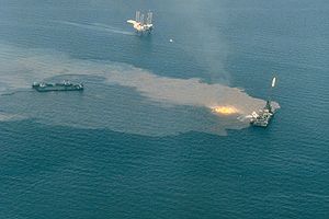 Ixtoc I oil well blowout
Kick is the entry of formation fluid into the wellbore during drilling operations. It occurs because the pressure exerted by the column of drilling fluid is not great enough to overcome the pressure exerted by the fluids in the formation drilled. The whole essence of oil well control is to prevent kick from occurring and if it happens to prevent it from developing into blowout. An uncontrolled kick must times are as a result of proper equipment not deployed, poor practices and lack of training of the rig crews. Loss of oil well control may lead into blowout, which represent one of the most severe threat associated with exploration of petroleum resources involving the risk of lives and environmental and economic consequences. [32][33]
Causes of kicks
A kick will occur when the bottom hole pressure(BHP) of a well falls below the formation pressure and the formation fluid flows into the wellbore.There are usually causes for kicks some of which are:
- Failure to keep the Hole full during a Trip
- Swabbing while tripping
- Lost circulation
- Insufficient density of fluid
- Abnormal pressure
- Drilling Into an Adjacent Well
- Lost control during drill stem test
Failure to keep the Hole full during a Trip
Tripping is the complete operation of removing the drillstring from the wellbore and running it back in the hole. This operation is typically undertaken when the bit(which is the tool used to crush or cut rock during drilling) becomes dull or broken, and no longer drills the rock efficiently.
Tripping out of the hole means a volume of steel(of drillstring) is been removed from the well. This displacement of the drill string( the steel) will leave out a volume of space that must be replaced with equal volume of mud. If the replacement is not done, the fluid level in the wellbore will drop resulting in a loss of hydrostatic pressure(HSP) and bottom hole pressure(BHP). If this bottom hole pressure reduction goes below the formation pressure, a kick will definitely occur.
Swabbing while tripping
Swabbing occurs when bottom hole pressure is reduced due to the effects of pulling the drill string or upward movement of pipe in a well. During tripping out of the hole, the space formerly by the drillpipe, drill collar,or tubing which are being removed must be replaced by something usually mud. If the rate of tripping out is greater than the rate the mud is being used to fill the void space created by the removal of the drill string, then swab will occur. If the reduction in bottom hole pressure caused by swabbing is below formation pressure,then a kick will occur.
Lost circulation
lost circulation usually occurs when the hydrostatic pressure fractures an open formation. When this occurs there is loss in circulation and the height of the fluid column decreases leading to lower HSP in the wellbore. A kick can occur if steps are not taken to keep the hole full. Lost circulation can be caused by:
- Excessive mud weights
- Excessive annular friction loss
- Excessive surge pressure during trips or spudding the bit
- Excessive shut-in pressures
Insufficient density of fluid
If the density of the drilling fluid or mud in the well bore is not sufficient to keep the formation pressure in check then a kick can occur. Insufficient density of the drilling fluid can be as a result of the following :
- attempting to drill underbalanced
- excessive dilution of the mud
- heavy rains in the pits
- barite settling in the pits
- spotting low density pills in the well
Abnormal pressure
Another cause of kicks is drilling accidentally into abnormally pressured permeable zones. The increased formation pressure may be greater than the bottom hole pressure resulting in a kick.
Drilling Into an Adjacent Well
Drilling into an adjacent well is a potential problem, particularly offshore where a large number of directional wells are drilled from the same platform. If the drilling well penetrates the production string of a previously completed well, the formation fluid from the completed well will enter the wellbore of the drilling well, causing a kick. If this occurs at a shallow depth, it is an extremely dangerous situation and could easily result in an uncontrolled blowout.
Lost control during drill stem test
A drill stem test is performed by setting a packer above the formation to be tested, and allowing the formation to flow.During the course of the test, the bore hole or casing below the packer, and at least a portion of the drill pipe or tubing, is filled with formation fluid. At the conclusion of the test, this fluid must be removed by proper well control techniques to return the well to a safe condition. Failure to follow the correct procedures to kill the well could lead to a blowout. [34][35][36]
Kick warning signs
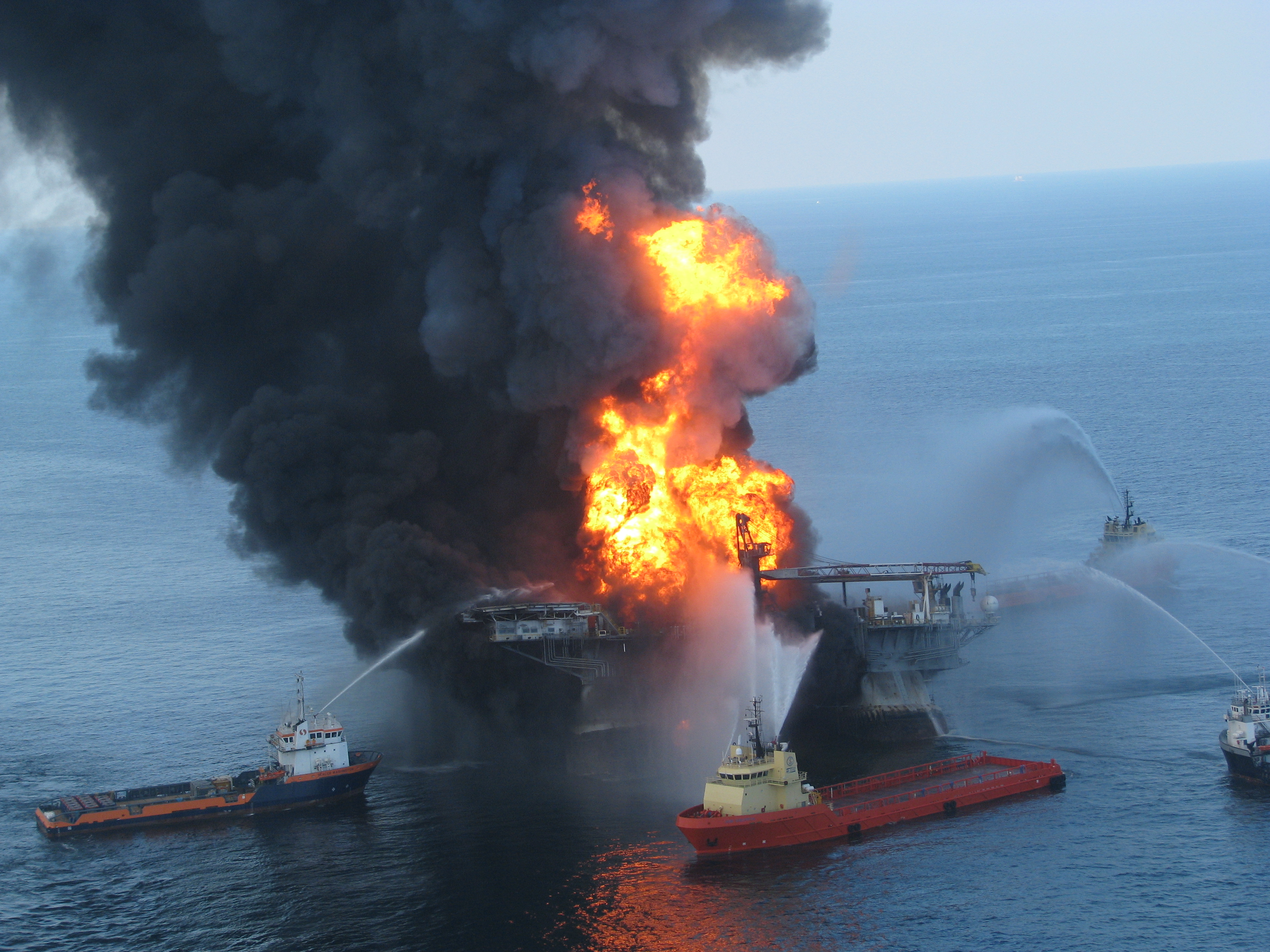
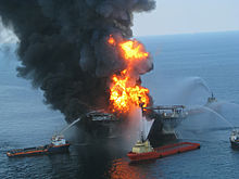 Deepwater Horizon drilling rig blowout, 21 April 2010
In oil well control a kick should be able to be detected promptly and proper kick prevention operation taken immediately to avoid blowout.There are various signs that tell-tale signs a kick will give, knowing these signs will allows oil well control to be carried out promptly to avert blowout.
Sudden increase in drilling rate
A sudden increase in penetration rate (drilling break) is usually caused by a change in the type of formation being drilled: however, it may also signal an increase in formation pore pressure which may indicate a possible kick.
Increase in Annulus flow rate
If the rate at which the pumps are running is held constant, the flow from the annulus should be constant. If the annulus flow increases without a corresponding change in pumping rate, the additional flow is caused by formation fluid(s) feeding into the wellbore or gas expansion.This will indicate an impending kick.
Gain in pit volume
If there is an unexplained increase in volume of surface mud pit(a large tank that holds drilling fluid on the rig) it could signifies an impending kick. This is because as the formation fluid feeds into the wellbore, it causes more drilling fluid to flow from the annulus than is pumped down the drill string, thus the volume of fluid in the pit(s) increases.
Change in Pump Speed or Pressure
A decrease in pump pressure or increase in pump speed is as a result of a decrease in hydrostatic pressure of the annulus as the formation fluids enters the wellbore.As the lighter formation fluid flows into the wellbore, the hydrostatic pressure exerted by the annular column of fluid decreases, and the drilling fluid in the drill pipe tends to U-tube into the annulus. When this occurs, the pump pressure will drop and the pump speed will increase. The lower pump pressure and increase in pump speed symptoms are also indicative of a hole in the drill string, commonly referred to as a washout. Until a confirmation can be made whether a washout or a well kick has occurred, a kick should be assumed.
Improper fill on Trips
Improper fill on trip occurs when volume of drilling fluid to Keep the hole full on a Trip(complete operation of removing the drillstring from the wellbore and running it back in the hole) is less than that calculated or less than Trip Book Record.This condition is usually caused by formation fluid entering the wellbore due to the swabbing action of the drill string and if action is not taken soon, the well will enter a kick state.[37][38][39]
Categories of Oil Well control
There are basically there types of oil well control which are:
- Primary oil well control
- Secondary oil well control
- Tertiary oil well Control
Primary oil well control
Primary oil well control is the process which maintains a hydrostatic pressure in the wellbore greater than the pressure of the fluids in the formation being drilled, but less than formation fracture pressure.It uses the mud weight to provide sufficient pressure to prevent an influx of formation fluid into the wellbore If hydrostatic pressure is less than formation pressure then formation fluids will enter the wellbore. If the hydrostatic pressure of the fluid in the wellbore exceeds the fracture pressure of the formation then the fluid in the well could be lost. In an extreme case of lost circulation the formation pressure may exceed hydrostatic pressure allowing formation fluids to enter into the well.
Secondary oil well control
Secondary oil well control is done after the Primary oil well control has failed to prevent formation fluids entering the wellbore.This process is stopped using a “blow out preventer”,BOP to prevent the escape of wellbore fluids from the well.
Tertiary oil well control
Tertiary oil well control describes the third line of defence. Where the formation cannot be controlled by primary or secondary well control (hydrostatic and equipment). This happens in Underground blowout situations.These following examples are tertiary well control:
- Drill a relief well to hit an adjacent well that is flowing and kill the well with heavy mud
- Rapid pumping of heavy mud to control the well with equivalent circulating density
- Pump barite or heavy weighting agents to plug the wellbore in order to stop flowing
- Pump cement to plug the wellbore[40][41][42][43]
Shut-in Procedures
Shut-in Procedures is one of the oil well control measure to curtail kicks and prevent blowout from occurring.Shut in procedures are specific procedures for closing a well in case of well control situation.When any positive indication of a kick is observed such as a sudden increase in flow or an increase in pit level, then the well should be shut in immediately.If a well shut-in is not done promptly,a blowout is likely to happen.
Shut-in procedures are usually developed and practiced for every rig activity such as, drilling, tripping, logging, running tubular, performing a drill stem test and so on and the main reason to have the specific shut in procedure is to minimize kick volume entering into a wellbore when well control situation occurs.It should however be noted that shut in procedure is a company specific procedure and the policy of a company will dictate a well should be shut-in.
They are generally two type of Shut-in procedures which are:
- Soft Shut-In
- Hard Shut-In
Among the two methods, the hard shut-in is the fastest method to shut in the well; therefore, it will minimize volume of kick allowed into the wellbore.[44]
Well kill procedures
Well kill procedure is an oil well control method. Once the well has been shut-in on a kick, proper kill procedures must be done immediately. The general idea in well kill procedure is to circulate out any formation fluid already in the wellbore during kick and circulate a satisfactory weight of kill mud called Kill Weight Mud (KWM) into the well without allowing further fluid into the hole.If this can be done, then once the kill mud has been fully circulated around the well, it is possible to open up the well and restart normal operations. Generally, a kill mud( KWM) which just provides hydrostatic balance for formation pressure is circulated. This allows approximately constant bottom hole pressure which is slightly greater than formation pressure to be maintained as the kill circulation proceeds because of the additional small circulating friction pressure loss. After circulation, the well is opened up again.
The major well kill procedures used in oil well control are listed below:
- Wait and Weight
- Driller method
- Circulate and Weight
- Concurrent Method
- Reverse Circulation
- Dynamic Kill procedure
- Bullheading
- Volumetric Method
- Lubricate and Bleed[45][46]
Oil Well Control Incidents - Root causes
There will always be oil well control problems as long as there are drilling operations anywhere in the world.Most of these well control problems are as a result of some errors and can be eliminated,even though some are actually unavoidable.Since we know the consequences of failed well control are severe, effort should be made to prevent some human errors which are the root causes of these incidents. These causes include:
- Lack of knowledge and skills of rig personnel
- Improper work practices
- Lack of understanding of oil well control training
- Lack of application of policies and standards
- Inadequate Risk Management[47]
Organizations for building Oil well control culture
Good oil well control culture requires personnels involve in oil well control to develop a core value for it by doing the proper thing at the proper time. A good well control culture will definitely minimize well control incidents.Building well control culture would involve developing competent personnel that are able to recognize well control problems and know what to do to mitigate against them. This is usually done through quality assured programs and training. These programs are done by organizations such as International Association of Drilling Contractors(IADC) and International Well Control Forum(IWCF)
IADC operates the Well-Control accreditation Program(WellCAP)which is a training aimed at providing the necessary knowledge and practical skills critical to successful well control and to develop competent rig personnel.This training starts with floor-hand level and continued to the most-experienced drilling personnel.
IWCF is an NGO whose main aim is to develop and administer well control certification programmes for personnel employed in oil well Drilling, Workover and Well Intervention operations.[48][49][50]
See also
- Blowout (well drilling)
- Oil well fire
- Formation fluid
- Oil well
References
- ^ Lyons, William C.; Plisga, Gary J. (2005). Standard Handbook of Petroleum and Natural Gas Engineering (2nd Edition).. Elsevier. Online version available at: http://www.knovel.com/web/portal/browse/display?_EXT_KNOVEL_DISPLAY_bookid=1233&VerticalID=0,p.4-371(eBook version)
- ^ Oil and Gas glossary," Kick","Oil and Gas Field Technical Terms Glossary",retrieved on 8th April,2011
- ^ Schlumberger article," Well control","Schlumberger OilField Glossary",retrieved on 9th April,2011
- ^ Oil and Gas glossary," Primary Well control","Oil and Gas Field Technical Terms Glossary",retrieved on 8th April,2011
- ^ Jerome Schubert, "Managed-Pressure Drilling: Kick Detection and Well Control" Section:"Kick Detection While Drilling","Society of Petroleum Engineer- Journal of Petroleum Technology(JPT), Well control focus archived 2010/01/15"
- ^ Jerome Jacob Schubert,"Well control", "Texas A&M University MEng Report for well control" (December 1995), retrieved on 2011-01-04 p.I-1
- ^ Jerome Jacob Schubert,"Well control", "Texas A&M University MEng Report for well control" (December 1995), retrieved on 2011-01-04 p.I-1
- ^ Karen Bybee, "A Well-Specific Approach to the Quantification of Well Control","Society of Petroleum Engineer- Journal of Petroleum Technology(JPT), Well control focus archived 2010/01/15 page 60"
- ^ Jerome Jacob Schubert,"Well control", "Texas A&M University MEng Report for well control" (December 1995), retrieved on 2011-01-04 p.I-2
- ^ Oil and Gas glossary, " Hydrostatic Pressure","Oil and Gas Field Technical Terms Glossary", retrieved on 8 April 2011
- ^ Micheal Nelkon & Philip Parker, Advanced Level Physics, 7th Edition, New Delhi India, CBS Publishers, 1995, p. 103–105, ISBN 81-239-0400-2
- ^ Jerome Jacob Schubert,"Well control", "Texas A&M University MEng Report for well control" (December 1995), retrieved on 2011-01-04 p.1-1,2
- ^ Schlumberger Limited article,"Hydrostatic pressure", "Schlumberger OilField Glossary", retrieved on 9 April 2011
- ^ Jerome Jacob Schubert,"Well control", "Texas A&M University MEng Report for well control" (December 1995), retrieved on 2011-01-04 p. 1-2
- ^ Jerome Jacob Schubert, "Well control", "Texas A&M University MEng Report for well control" (December 1995), retrieved on 2011-01-04 p. 1-2
- ^ Schlumberger Limited article, "Abnormal Pressure", "Schlumberger OilField Glossary", retrieved on 2011-04-09
- ^ Schlumberger Limited article, "UnderPressure", "Schlumberger OilField Glossary",retrieved on 9th April,2011
- ^ Schlumberger Limited article, "Normal Pressure", "Schlumberger OilField Glossary", retrieved on 2011-04-09
- ^ Jerome Jacob Schubert,"Well control", "Texas A&M University MEng Report for well control" (December 1995), retrieved on 2011-01-04 p. 1-3,4
- ^ Rehm, Bill; Schubert, Jerome; Haghshenas, Arash; Paknejad, Amir Saman; Hughes, Jim (2008). Managed Pressure Drilling.. Gulf Publishing Company. Online version available at: http://www.knovel.com/web/portal/browse/display?_EXT_KNOVEL_DISPLAY_bookid=2548&VerticalID=0 p.22,23 section 1.7 (online version)
- ^ Jerome Jacob Schubert,"Well control", "Texas A&M University MEng Report for well control" (December 1995), retrieved on 2011-01-04 p. 1-4
- ^ Rehm, Bill; Schubert, Jerome; Haghshenas, Arash; Paknejad, Amir Saman; Hughes, Jim (2008). Managed Pressure Drilling. Gulf Publishing Company. Online version available at: http://www.knovel.com/web/portal/browse/display?_EXT_KNOVEL_DISPLAY_bookid=2548&VerticalID=0 p.23 section 1.8.1 (online version)
- ^ Jerome Jacob Schubert,"Well control", "Texas A&M University MEng Report for well control" (December 1995), retrieved on 2011-01-04 p.1-4,5,6,7
- ^ Oil and Gas glossary, "Circulate","Oil and Gas Field Technical Terms Glossary",retrieved on 8th April,2011
- ^ Schlumberger Limited article,"Circulate","Schlumberger OilField Glossary",retrieved on 9th April,2011
- ^ Jerome Jacob Schubert,"Well control", "Texas A&M University MEng Report for well control" (December 1995), retrieved on 2011-01-04 p.1-7
- ^ Jerome Jacob Schubert, "Well control", "Texas A&M University MEng Report for well control" (December 1995), retrieved on 2011-01-04 p. 1-8,9,10
- ^ Rehm, Bill; Schubert, Jerome; Haghshenas, Arash; Paknejad, Amir Saman; Hughes, Jim (2008). Managed Pressure Drilling. Gulf Publishing Company. Online version available at: http://www.knovel.com/web/portal/browse/display?_EXT_KNOVEL_DISPLAY_bookid=2548&VerticalID=0 p.11 section 1.4.1 (online version)
- ^ Jerome Jacob Schubert,"Well control", "Texas A&M University MEng Report for well control" (December 1995), retrieved on 2011-01-04 p.2-1
- ^ Jerome Jacob Schubert,"Well control", "Texas A&M University MEng Report for well control" (December 1995), retrieved on 2011-01-04 p.2-1,2
- ^ Jerome Jacob Schubert,"Well control", "Texas A&M University MEng Report for well control" (December 1995), retrieved on 2011-01-04 p.2-4,6
- ^ Schlumberger Limited article,"Kick","Schlumberger OilField Glossary",retrieved on 9th April,2011
- ^ IDPT/IPM article,"Basic Well Control"," Basic well control article on Scribd site" accessed 10/04/2011, p.3
- ^ Jerome Jacob Schubert,"Well control", "Texas A&M University MEng Report for well control" (December 1995), retrieved on 2011-01-04 p.3-1,2,3,4
- ^ IDPT/IPM article,"Basic Well Control"," Basic well control article on Scribd site" accessed 10/04/2011, p.19,20
- ^ Lyons, William C.; Plisga, Gary J. (2005). Standard Handbook of Petroleum and Natural Gas Engineering (2nd Edition).. Elsevier. Online version available at: http://www.knovel.com/web/portal/browse/display?_EXT_KNOVEL_DISPLAY_bookid=1233&VerticalID=0, p.39,40,41, Chap 2
- ^ Jerome Jacob Schubert,"Well control", "Texas A&M University MEng Report for well control" (December 1995), retrieved on 2011-01-04 p.4-1,2,3,4
- ^ Grace, Robert D. (2003). Blowout and Well Control Handbook.. Elsevier. Online version available at: http://www.knovel.com/web/portal/browse/display?_EXT_KNOVEL_DISPLAY_bookid=1272&VerticalID=0 p.42,43 chap 2.(online version)
- ^ Rehm, Bill; Schubert, Jerome; Haghshenas, Arash; Paknejad, Amir Saman; Hughes, Jim (2008). Managed Pressure Drilling.. Gulf Publishing Company. Online version available at: http://www.knovel.com/web/portal/browse/display?_EXT_KNOVEL_DISPLAY_bookid=2548&VerticalID=0 p. 212,213 section 8.6.2(online version)
- ^ IDPT/IPM article,"Basic Well Control"," Basic well control article on Scribd site" accessed 2011-04-11, p.7
- ^ Rachain Jetjongjit,"What is Tertiary well control", Drilling Formulas and Drilling Calculations, accessed 2011-04-11
- ^ Rachain Jetjongjit,"What is Primary well control", Drilling Formulas and Drilling Calculations, accessed 2011-04-11
- ^ Rachain Jetjongjit,"What is Secondary well control", Drilling Formulas and Drilling Calculations, accessed 2011-04-11
- ^ Jerome Jacob Schubert,"Well control", "Texas A&M University MEng Report for well control" (December 1995), retrieved on 2011-01-04 p.5-1
- ^ Jerome Jacob Schubert,"Well control", "Texas A&M University MEng Report for well control" (December 1995), retrieved on 2011-01-04 p.6-1-13
- ^ IDPT/IPM article,"Basic Well Control"," Basic well control article on Scribd site" accessed 10/04/2011, p.37,38
- ^ IDPT/IPM training material,"Basic Well Control"," Basic well control article on Scribd site" accessed 10/04/2011, p.4
- ^ Kareen Bybee, "Building a Well-Control Culture","Society of Petroleum Engineer- Journal of Petroleum Technology(JPT), Well control focus archived 2009/01/16" p.73
- ^ IADC,"WellCAP", "International Association of Drilling Contractors Well-Control Accreditation Program, accessed 2011-04-12
- ^ IWCF,"International Well Control forum organization" accessed 2011-04-12
Categories:- Oil spills
- Oilfield terminology
- Oil wells
- Petroleum geology
- Drilling technology
- Petroleum engineering

Wikimedia Foundation. 2010.