- Chirp
-
For other uses, see Chirp (disambiguation).
A chirp is a signal in which the frequency increases ('up-chirp') or decreases ('down-chirp') with time. In some sources, the term chirp is used interchangeably with sweep signal.[1] It is commonly used in sonar and radar, but has other applications, such as in spread spectrum communications. In spread spectrum usage, SAW devices such as RACs are often used to generate and demodulate the chirped signals. In optics, ultrashort laser pulses also exhibit chirp, which, in optical transmission systems interacts with the dispersion properties of the materials, increasing or decreasing total pulse dispersion as the signal propagates.
Contents
Types of chirp
Linear chirp
In a linear chirp, the instantaneous frequency f(t ) varies linearly with time:
- f(t) = f0 + kt
where f0 is the starting frequency (at time t = 0), and k is the rate of frequency increase or chirp rate. The corresponding time-domain function for a sinusoidal linear chirp is:
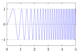 A linear chirp waveform; a sinusoidal wave that increases in frequency linearly over time
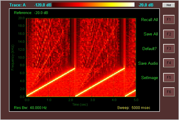
 Spectrogram of a Linear Chirp. The Spectrogram plot demonstrates the linear rate of change in frequency as a function of time, in this case from 0 to 7 kHz repeating every 2.3 seconds. The intensity of the plot is proportional to the energy content in the signal at the indicated frequency and time.
In the frequency domain, the instantaneous frequency described by the equation f(t) = f0 + kt is accompanied by additional frequencies (harmonics) which exist as a fundamental consequence of Frequency Modulation. These harmonics are quantifiably described through the use of Bessel Functions. However with the aid of Frequency vs. Time profile Spectrogram one can readily see that the linear chirp has spectral components at harmonics of the fundamental chirp.
Exponential chirp
In a geometric chirp, also called an exponential chirp, the frequency of the signal varies with a geometric relationship over time. In other words, if two points in the waveform are chosen, t1 and t2, and the time interval between them t2 − t1 is kept constant, the frequency ratio f(t2)/f(t1) will also be constant.
In an exponential chirp, the frequency of the signal varies exponentially as a function of time:
- f(t) = f0kt
where f0 is the starting frequency (at t = 0), and k is the rate of exponential increase in frequency. Unlike the linear chirp, which has a constant chirp rate, an exponential chirp has an exponentially increasing chirp rate. The corresponding time-domain function for a sinusoidal exponential chirp is:
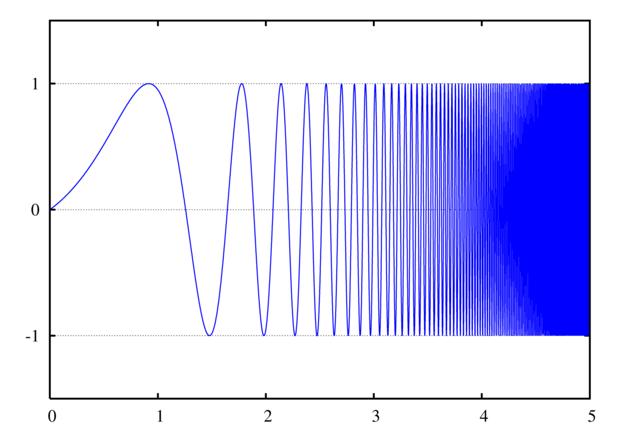
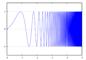 An exponential chirp waveform; a sinusoidal wave that increases in frequency exponentially over time
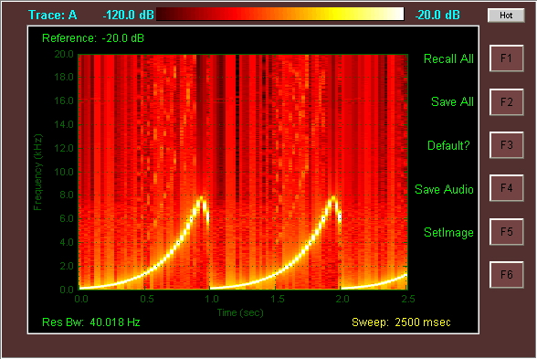
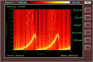 Spectrogram of an exponential chirp. The exponential rate of change of frequency is shown as a function of time, in this case from 0 to 8 kHz repeating every second. Also visible in this Spectrogram is a frequency fallback to 6 kHz after peaking, likely an artifact of the specific method employed to generate the waveform.
As was the case for the Linear Chirp, the instantaneous frequency of the Exponential Chirp consists of the fundamental frequency f(t) = f0kt accompanied by additional harmonics.
Although somewhat harder to generate, a geometric chirp does not suffer from reduction in correlation gain if the echo is Doppler-shifted by a moving target. This is because the Doppler shift actually scales the frequencies of a wave by a multiplier (shown below as the constant c).
- f(t)Doppler = cf(t)Original
From the equations above, it can be seen that this actually changes the rate of frequency increase of a linear chirp (kt multiplied by a constant) so that the correlation of the original function with the reflected function is low.
Because of the geometric relationship, the Doppler shifted geometric chirp will effectively start at a different frequency (f0 multiplied by a constant), but follow the same pattern of exponential frequency increase, so the end of the original wave, for instance, will still overlap perfectly with the beginning of the reflected wave, and the magnitude of the correlation will be high for that section of the wave.
Generation of a chirp signal
A chirp signal can be generated with analog circuitry via a VCO, and a linearly or exponentially ramping control voltage. It can also be generated digitally by a DSP and DAC, using a Direct digital synthesizer (DDS) and by varying the step in the numerically controlled oscillator.
Uses and occurrences
Chirp modulation
Chirp modulation, or linear frequency modulation for digital communication was patented by Sidney Darlington in 1954 with significant later work performed by Winkler in 1962. This type of modulation employs sinusoidal waveforms whose instantaneous frequency increases or decreases linearly over time. These waveforms are commonly referred to as linear chirps or simply chirps.
Hence the rate at which their frequency changes is called the chirp rate. In binary chirp modulation, binary data is transmitted by mapping the bits into chirps of opposite chirp rates. For instance, over one bit period "1" is assigned a chirp with positive rate a and "0" a chirp with negative rate −a. Chirps have been heavily used in radar applications and as a result advanced sources for transmission and matched filters for reception of linear chirps are available.[2]
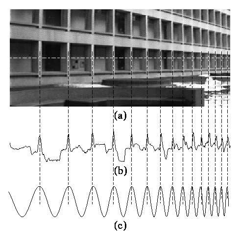
 (a) In image processing, direct periodicity seldom occurs, but, rather, periodicity-in-perspective is encountered. (b) Repeating structures like the alternating dark space inside the windows, and light space of the white concrete, "chirp" (increase in frequency) to towards the right. (c) Thus the best fit chirp for image processing is often a projective chirp.
Chirplet transform
Main article: Chirplet transformAnother kind of chirp is the projective chirp, of the form
![\scriptstyle g = f\left[\frac{a \cdot x + b}{c \cdot x + 1}\right]](5/295161c1a0dfa8b6af96200ccaed90d5.png) , having the three parameters a (scale), b (translation), and c (chirpiness). The projective chirp is ideally suited to image processing, and forms the basis for the projective chirplet transform.
, having the three parameters a (scale), b (translation), and c (chirpiness). The projective chirp is ideally suited to image processing, and forms the basis for the projective chirplet transform.Key chirp
A change in frequency of Morse code from the desired frequency, due to poor stability in the RF Oscillator is known as chirp,[3] and in the RST code is given an appended letter 'C'.
See also
- Chirplet transform - A signal representation based on a family of localized chirp functions, each member of which can usually be expressed as parameterized transformations of each other.
- Pulse compression - A signal processing technique designed to maximize the sensitivity and resolution of radar systems by modifying transmitted pulses to improve their auto-correlation properties. One way of accomplishing this is to chirp the RADAR signal (also known as Chirp Radar).
- Chirp Spread Spectrum - A part of the wireless telecommunications standard IEEE 802.15.4a CSS (see Chirp Spread Spectrum (CSS) PHY Presentation for IEEE P802.15.4a).
- Continuous-wave radar
- SHARAD
- Chirped pulse amplification
- Chirped mirror
- Dispersion (optics)
References
- ^ Weisstein, Eric W. "Sweep Signal." From MathWorld--A Wolfram Web Resource. http://mathworld.wolfram.com/SweepSignal.html
- ^ http://www.stanford.edu/~hengstle/References/Reference_5.pdf
- ^ The Beginner's Handbook of Amateur Radio By Clay Laster
Categories:
![x(t) = \sin\left[2 \pi \int_0^t f(t')\, dt'\right] = \sin\left[2 \pi \int_0^t (f_0 + k t')\, dt'\right] = \sin\left[2\pi (f_0 + \frac{k}{2} t) t \right]](6/47629a8b6caa7bc55959a3c999fed9dc.png)

![x(t) = \sin\left[2 \pi \int_0^t f(t')\, dt'\right] = \sin\left[2 \pi f_0 \int_0^t k^{t'} dt'\right] = \sin\left[2\pi f_0 \frac{k^t - 1}{\ln(k)}\right]](a/23ab8305afef87064a0a55fa649ad0cd.png)
Wikimedia Foundation. 2010.