- Chirplet transform
-
In signal processing, the chirplet transform is an inner product of an input signal with a family of analysis primitives called chirplets.
Contents
Similarity to other transforms
Much as in the wavelet transform, the chirplets are usually generated from (or can be expressed as being from) a single mother chirplet (analogous to the so-called mother wavelet of wavelet theory).
What is the chirplet and chirplet transform?
The term chirplet transform was coined by Steve Mann, as the title of the first published paper on chirplets. The term chirplet itself (apart from chirplet transform) was also used by Steve Mann, Domingo Mihovilovic, and Ronald Bracewell to describe a windowed portion of a chirp function. In Mann's words:
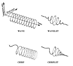
A wavelet is a piece of a wave, and a chirplet, similarly, is a piece of a chirp. More precisely, a chirplet is a windowed portion of a chirp function, where the window provides some time localization property. In terms of time–frequency space, chirplets exist as rotated, sheared, or other structures that move from the traditional parallelism with the time and frequency axes that are typical for waves (Fourier and short-time Fourier transforms) or wavelets.The chirplet transform thus represents a rotated, sheared, or otherwise transformed tiling of the time–frequency plane. Although chirp signals have been known for many years in radar, pulse compression, and the like, the first published reference to the chirplet transform described specific signal representations based on families of functions related to one another by time–varying frequency modulation or frequency varying time modulation, in addition to time and frequency shifting, and scale changes. In that paper, the Gaussian chirplet transform was presented as one such example, together with a successful application to ice fragment detection in radar (improving target detection results over previous approaches). The term chirplet (but not the term chirplet transform) was also proposed for a similar transform, apparently independently, by Mihovilovic and Bracewell later that same year.
Applications
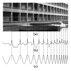
 (a) In image processing, periodicity is often subject to a linear scaling. (b) In this image, repeating structures like the alternating dark space inside the windows, and light space of the white concrete, chirp (increase in frequency) towards the right. (c) The chirplet transform is able to represent this modulated variation compactly.
The chirplet transform is a useful signal analysis and representation framework that is widely used[citation needed] in
- Radar;
- Biomedical, the most commonly and widely used chirplet applications in biomedical being:
- Heart sound processing;
- EEG processing.[1]
- Signal processing;
- Image processing;
- SETI@home uses chirp functions to compensate for Doppler drift;[citation needed]
- Chirplet Time Domain Reflectometry.[2]
Taxonomy of chirplet transforms
There are two broad categories of chirplet transform:
- Fixed
- Adaptive
These categories may be further subdivided by:
- choice of chirp
- choice of window
In either the fixed or adaptive case, the chirplets may be:
- q-chirplets (quadratic chirplets) of the form exp[i2π(at2 + bt + c)] or, in general, some kind of quadratically varying exponent, linear swept wave packet, or the like. These are sometimes called linear FM chirplets (linear frequency-modulated chirplets, since quadratic phase is linear frequency). Commonly used families of q-chirplets are metaplectomorphisms of one another (i.e., the energy distribution of any member of the family of q-chirplets can be generated from any other member by shear-in-time, shear-in-frequency, dilation, translation-in-time, and translation-in-frequency).
- w-chirplets, also known as warblets. A family of warblets are like the sound made by birds called warblers. Unwindowed warblets have a sinusoidally varying time–frequency distribution, or similar cyclostationary or periodically varying time–frequency plot. The sound of a police siren is an example, in which the pitch goes up and down periodically. Of course, the warblet is a "piece of" a warble (i.e., a windowed section of something that has a time–frequency periodicity).
- d-chirplets, also known as Doppler chirplets. These are analysis functions that mimic the Doppler shift of a passing tone (e.g., the sound you hear from a train whistle as it moves past).
- p-chirplets, in which the scale varies projectively. Whereas the wavelet transform is based on wavelets of the form g(ax + b), the p-type chirplet transform is based on chirplets of the form g((ax + b)/(cx + 1)), where a is the scale, b is the translation, and c is the chirpiness (chirp-rate, as defined by the degree of perspective, or projection).
The choice of window is also another matter of decision. A Gaussian window is one possible choice, leading to a four parameter chirplet transform (for which time–shear and frequency–shear only give one degree of freedom that may thus be encapsulated as rotation angle—Radon transform of the Wigner distribution may, for example, be used, as may the fractional Fourier transform).
Another possible choice is the rectangular window, and discrete prolate spheroidal sequences ( also called Multitaper#The_Slepian_sequences ) may be used, by way of the method of multiple mother chirplets. This method gives a total chirplet transform as the sum of energies in various contributory chirplet transforms made from multiple windows, akin to the way in which DPSSs are used to get a perfect rectangular tiling of the time–frequency plane. Thus it is now possible to get perfect parallelogram tiling of the time–frequency plane, using the method of multiple mother chirplets.
Related work
The chirplet transform is a generalized representation that includes as special cases:
- The Fourier transform
- The short-time Fourier transform (STFT), also known as the spectrogram
- The Wigner-Ville distribution
- The wavelet transform
- Canonical conjugate variables
- Segal–Shale–Weil distribution
Josef Segman proposed the idea of incorporating scale into the Heisenberg group (position, momentum, phase, or equivalently any canonical conjugate variables taken together with phase, such as, for example, time, frequency, and phase). This gave rise to a four parameter space of time, frequency, phase, and scale. Segman introduced this idea of phase scale. (Personal communication with Mann, from Josef Segman, at Harvard University and at Massachusetts Institute of Technology). Further personal communication between Irving Segal (the principal behind the Segal, Shale Weil representation, known also as the metaplectic representation—a double covering of the symplectic group) and Mann led to additional insight into the chirplet transform, in particular, to the variation of the chirplet transform that is based on q-chirplets.
See also
- Time–frequency representation
Other time–frequency transforms:
External links
References
- ^ Cui, J. (17 February), "Time–frequency analysis of visual evoked potentials using chirplet transform", Electronics Letters 41 (4): 217–218, doi:10.1049/el:20056712, http://www.eyetap.org/papers/docs/CuiTime_frequency_chirplet_vep.pdf, retrieved 2010-07-29
- ^ http://zone.ni.com/devzone/cda/epd/p/id/5684
- The Chirplet Transform (web tutorial and info).
- S. Mann and S. Haykin, "The Chirplet transform: A generalization of Gabor's logon transform", Proc. Vision Interface 1991, 205–212 (3–7 June 1991).
- D. Mihovilovic and R. N. Bracewell, "Adaptive chirplet representation of signals in the time–frequency plane," Electronics Letters 27 (13), 1159–1161 (20 June 1991).
- Mann, S.; Haykin, S. (21–26 July, 1991), The adaptive chirplet: An adaptive wavelet like transform, "36th Intl. Symp. Optical and Optoelectronic Appl. Sci. Eng.", Proc. SPIE 1565, doi:10.1117/12.49794, http://wearcam.org/chirplet/adaptive_chirplet1991/ LEM, Logon Expectation Maximization
- Mann, S.; Haykin, S. (1992). "Adaptive chirplet transform". Optical Engineering 31 (6): 1243–1256. Bibcode 1992OptEn..31.1243M. doi:10.1117/12.57676. http://wearcam.org/chirplet/adaptive_chirplet1992/. introduces Logon Expectation Maximization (LEM) and Radial Basis Functions (RBF) in Time–Frequency space.
- Osaka Kyoiku, Gabor, wavelet and chirplet transforms...(PDF)
- J. "Richard" Cui, etal, Time–frequency analysis of visual evoked potentials using chirplet transform, IEE Electronics Letters, vol. 41, no. 4, pp. 217–218, 2005.
Categories:- Transforms
- Fourier analysis
- Time–frequency analysis
- Image processing
- Radar signal processing
Wikimedia Foundation. 2010.

