- Orifice plate
-
 Flat-plate, sharp-edge orifice
 ISO 5167 Orifice Plate
An orifice plate is a device used for measuring the volumetric flow rate. It uses the same principle as a Venturi nozzle, namely Bernoulli's principle which states that there is a relationship between the pressure of the fluid and the velocity of the fluid. When the velocity increases, the pressure decreases and vice versa.
Contents
Description
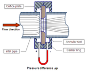
An orifice plate is a thin plate with a hole in the middle. It is usually placed in a pipe in which fluid flows. When the fluid reaches the orifice plate, with the hole in the middle, the fluid is forced to converge to go through the small hole; the point of maximum convergence actually occurs shortly downstream of the physical orifice, at the so-called vena contracta point (see drawing to the right). As it does so, the velocity and the pressure changes. Beyond the vena contracta, the fluid expands and the velocity and pressure change once again. By measuring the difference in fluid pressure between the normal pipe section and at the vena contracta, the volumetric and mass flow rates can be obtained from Bernoulli's equation.
Uses
Orifice plates are most commonly used for continuous measurement of fluid flow in pipes. They are also used in some small river systems to measure flow rates at locations where the river passes through a culvert or drain. Only a small number of rivers are appropriate for the use of the technology since the plate must remain completely immersed i.e the approach pipe must be full, and the river must be substantially free of debris.
A restrictive flow orifice, a type of orifice plate, is a safety device to control maximum flow from a compressed gas cylinder. [1]
In the natural environment large orifice plates are used to control onward flow in flood relief dams. In these structures a low dam is placed across a river and in normal operation the water flows through the orifice plate unimpeded as the orifice is substantially larger than the normal flow cross section. However, in floods, the flow rate rises and floods out the orifice plate which can then only pass a flow determined by the physical dimensions of the orifice. Flow is then held back behind the low dam in a temporary reservoir which is slowly discharged through the orifice when the flood subsides.
Incompressible flow through an orifice
By assuming steady-state, incompressible (constant fluid density), inviscid, laminar flow in a horizontal pipe (no change in elevation) with negligible frictional losses, Bernoulli's equation reduces to an equation relating the conservation of energy between two points on the same streamline:

or:

By continuity equation:
 or V1 = Q / A1 and V2 = Q / A2 :
Solving for Q:

and:

The above expression for Q gives the theoretical volume flow rate. Introducing the beta factor β = d2 / d1 as well as the coefficient of discharge Cd:

And finally introducing the meter coefficient C which is defined as
 to obtain the final equation for the volumetric flow of the fluid through the orifice:
Multiplying by the density of the fluid to obtain the equation for the mass flow rate at any section in the pipe:[2][3][4][5]

where: Q = volumetric flow rate (at any cross-section), m³/s 
= mass flow rate (at any cross-section), kg/s Cd = coefficient of discharge, dimensionless C = orifice flow coefficient, dimensionless A1 = cross-sectional area of the pipe, m² A2 = cross-sectional area of the orifice hole, m² d1 = diameter of the pipe, m d2 = diameter of the orifice hole, m β = ratio of orifice hole diameter to pipe diameter, dimensionless V1 = upstream fluid velocity, m/s V2 = fluid velocity through the orifice hole, m/s P1 = fluid upstream pressure, Pa with dimensions of kg/(m·s² ) P2 = fluid downstream pressure, Pa with dimensions of kg/(m·s² ) ρ = fluid density, kg/m³ Deriving the above equations used the cross-section of the orifice opening and is not as realistic as using the minimum cross-section at the vena contracta. In addition, frictional losses may not be negligible and viscosity and turbulence effects may be present. For that reason, the coefficient of discharge Cd is introduced. Methods exist for determining the coefficient of discharge as a function of the Reynolds number.[3]
The parameter
 is often referred to as the velocity of approach factor[2] and dividing the coefficient of discharge by that parameter (as was done above) produces the flow coefficient C. Methods also exist for determining the flow coefficient as a function of the beta function β and the location of the downstream pressure sensing tap. For rough approximations, the flow coefficient may be assumed to be between 0.60 and 0.75. For a first approximation, a flow coefficient of 0.62 can be used as this approximates to fully developed flow.
An orifice only works well when supplied with a fully developed flow profile. This is achieved by a long upstream length (20 to 40 pipe diameters, depending on Reynolds number) or the use of a flow conditioner. Orifice plates are small and inexpensive but do not recover the pressure drop as well as a venturi nozzle does. If space permits, a venturi meter is more efficient than an orifice plate.
Flow of gases through an orifice
In general, equation (2) is applicable only for incompressible flows. It can be modified by introducing the expansion factor Y to account for the compressibility of gases.

Y is 1.0 for incompressible fluids and it can be calculated for compressible gases.[3]
Calculation of expansion factor
The expansion factor Y, which allows for the change in the density of an ideal gas as it expands isentropically, is given by:[3]

For values of β less than 0.25, β4 approaches 0 and the last bracketed term in the above equation approaches 1. Thus, for the large majority of orifice plate installations:

where: Y = Expansion factor, dimensionless r = P2 / P1 k = specific heat ratio (cp / cv), dimensionless Substituting equation (4) into the mass flow rate equation (3):
}](8/458e68c20ebb3315d855d706e489f389.png)
and:
}](6/6867ad48c6268bd8442e3577bce09484.png)
and thus, the final equation for the non-choked (i.e., sub-sonic) flow of ideal gases through an orifice for values of β less than 0.25:
![(5)\qquad \dot{m} = C\;A_2\;\sqrt{2\;\rho_1\;P_1\;\bigg (\frac{k}{k-1}\bigg)\bigg[(P_2/P_1)^{2/k}-(P_2/P_1)^{(k+1)/k}\bigg]}](1/0315ea6c5d21a3785690c6d521f0e82b.png)
Using the ideal gas law and the compressibility factor (which corrects for non-ideal gases), a practical equation is obtained for the non-choked flow of real gases through an orifice for values of β less than 0.25:[4][5][6]
![(6)\qquad \dot{m} = C\;A_2\;P_1\;\sqrt{\frac{2\;M}{Z\;R\;T_1}\bigg(\frac{k}{k-1}\bigg)\bigg[(P_2/P_1)^{2/k}-(P_2/P_1)^{(k+1)/k}\bigg]}](1/bd14a9365979e9ab9b289af1b9afecd0.png)
Remembering that
 and
and  (ideal gas law and the compressibility factor)
![(8)\qquad Q_1 = C\;A_2\;\sqrt{2\;\frac{Z\;R\;T_1}{M}\bigg(\frac{k}{k-1}\bigg)\bigg[(P_2/P_1)^{2/k}-(P_2/P_1)^{(k+1)/k}\bigg]}](d/f3dbfcd54920079f849eb08511e17d11.png)
where: k = specific heat ratio (cp / cv), dimensionless = mass flow rate at any section, kg/s Q1 = upstream real gas flow rate, m³/s C = orifice flow coefficient, dimensionless A2 = cross-sectional area of the orifice hole, m² ρ1 = upstream real gas density, kg/m³ P1 = upstream gas pressure, Pa with dimensions of kg/(m·s²) P2 = downstream pressure, Pa with dimensions of kg/(m·s²) M = the gas molecular mass, kg/mol (also known as the molecular weight) R = the Universal Gas Law Constant = 8.3145 J/(mol·K) T1 = absolute upstream gas temperature, K Z = the gas compressibility factor at P1 and T1, dimensionless A detailed explanation of choked and non-choked flow of gases, as well as the equation for the choked flow of gases through restriction orifices, is available at Choked flow.
The flow of real gases through thin-plate orifices never becomes fully choked. "Cunningham (1951) first drew attention to the fact that choked flow will not occur across a standard, thin, square-edged orifice."[7] The mass flow rate through the orifice continues to increase as the downstream pressure is lowered to a perfect vacuum, though the mass flow rate increases slowly as the downstream pressure is reduced below the critical pressure.[8]
Permanent pressure drop for incompressible fluids
For a square-edge orifice plate with flange taps[9]:
where:
- ΔPp = permanent pressure drop
- ΔPi = indicated pressure drop at the flange taps
- β = d2 / d1
And rearranging the formula near the top of this article:
See also
- Accidental release source terms
- Choked flow
- Flowmeter
- De Laval nozzle
- Pitot tube
- Rocket engine nozzle
- Venturi effect
References
- ^ restrictive flow orifice
- ^ a b Lecture, University of Sydney
- ^ a b c d Perry, Robert H. and Green, Don W. (1984). Perry's Chemical Engineers' Handbook (Sixth Edition ed.). McGraw Hill. ISBN 0-07-049479-7.
- ^ a b Handbook of Chemical Hazard Analysis Procedures, Appendix B, Federal Emergency Management Agency, U.S. Dept. of Transportation, and U.S. Environmental Protection Agency, 1989. Handbook of Chemical Hazard Analysis, Appendix B Click on PDF icon, wait and then scroll down to page 391 of 520 PDF pages.
- ^ a b Risk Management Program Guidance For Offsite Consequence Analysis, U.S. EPA publication EPA-550-B-99-009, April 1999. Guidance for Offsite Consequence Analysis
- ^ Methods For The Calculation Of Physical Effects Due To Releases Of Hazardous Substances (Liquids and Gases), PGS2 CPR 14E, Chapter 2, The Netherlands Organization Of Applied Scientific Research, The Hague, 2005. PGS2 CPR 14E
- ^ Cunningham, R.G., "Orifice Meters with Supercritical Compressible Flow", Trans. ASME, Vol. 73, pp. 625-638, 1951
- ^ Section 3 -- Choked Flow
- ^ Catalog section by AVCO
External Links
Categories:


Wikimedia Foundation. 2010.