- Computer case screws
-
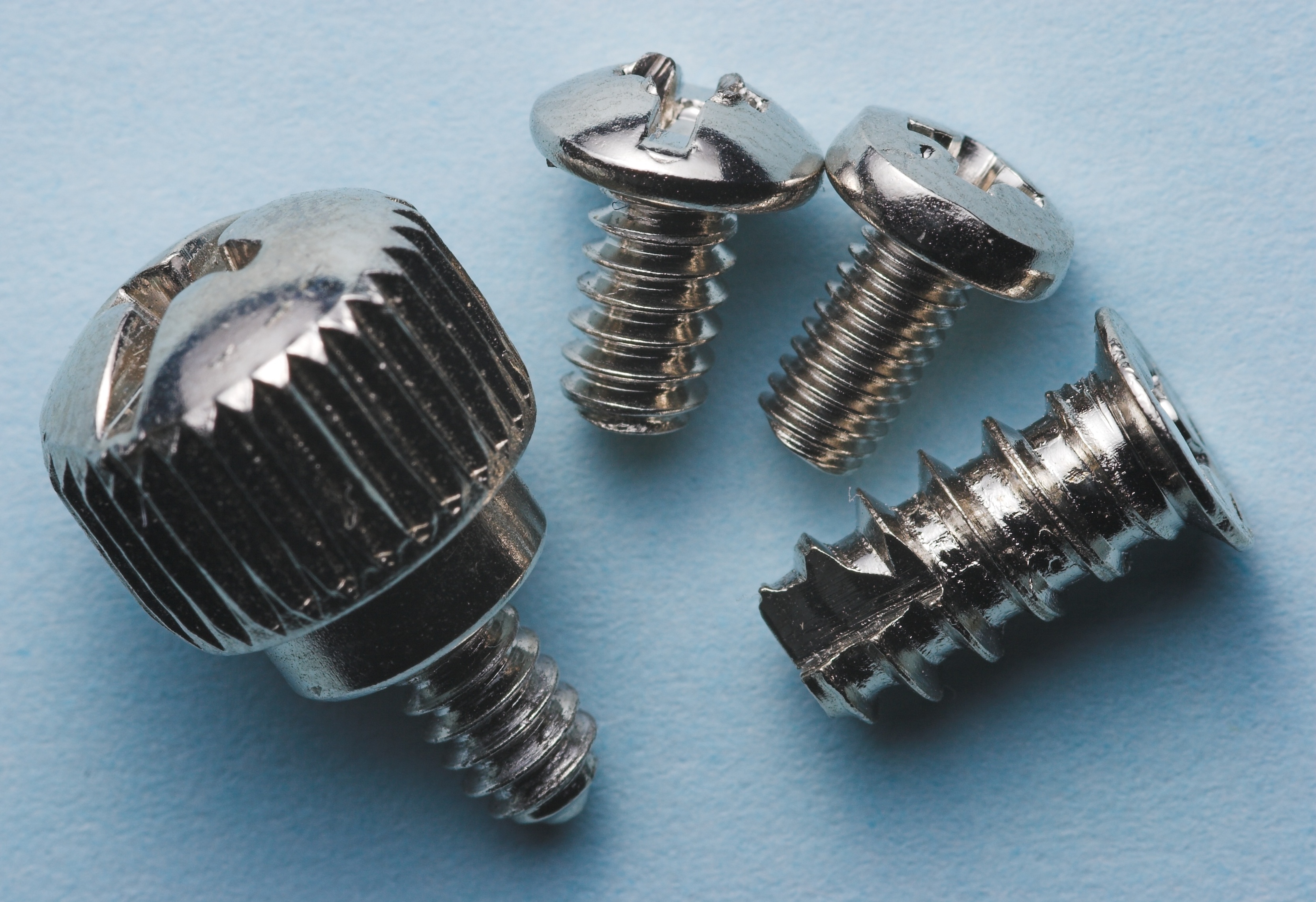
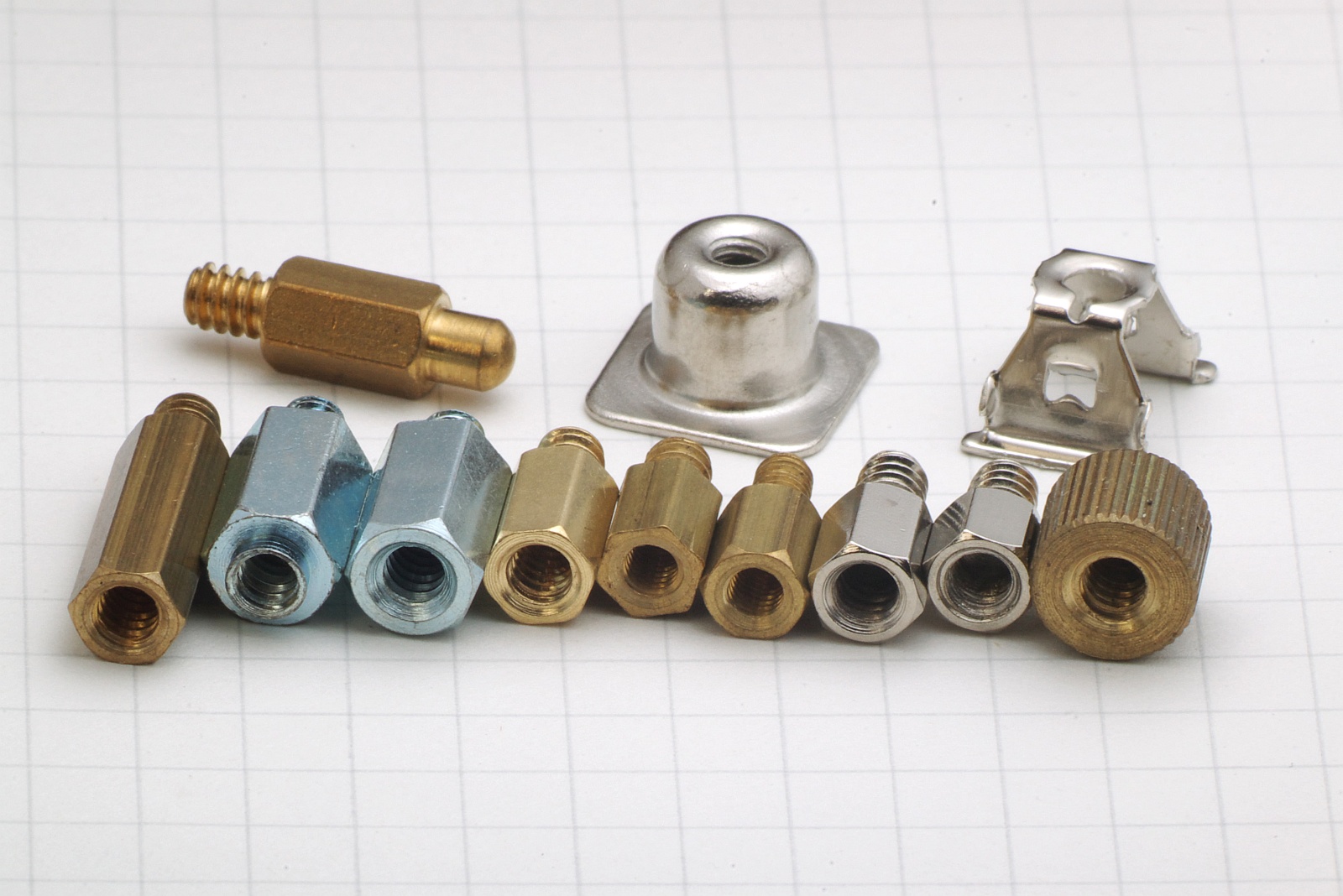
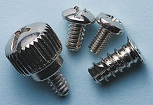 From left to right: a 6-32 thumbscrew, a 6-32 screw, an M3 screw, and a self-tapping screw for case fans
Computer case screws are the hardware used to fasten together parts of a computer case and to fasten the system components (such as motherboards, hard drives, and power supplies) to the case. Although there are numerous manufacturers of computer cases throughout the world, the computer industry has generally standardized on some specific screw thread measurements.[citation needed] The Unified Thread Standard (UTS) originates from the United States while the ISO metric screw thread is standardized worldwide. In turn, these thread standards define preferred size combinations that are based on generic units—some on the inch and others on the millimeter.
6-32 screw holes are often found on expansion cards (such as PCI cards) and hard disk drives. M3 screw holes are often found on optical disc drives and floppy drives. 4-40 jackscrews are often found on connectors at the ends of certain types of cables.
Contents
6-32 screw
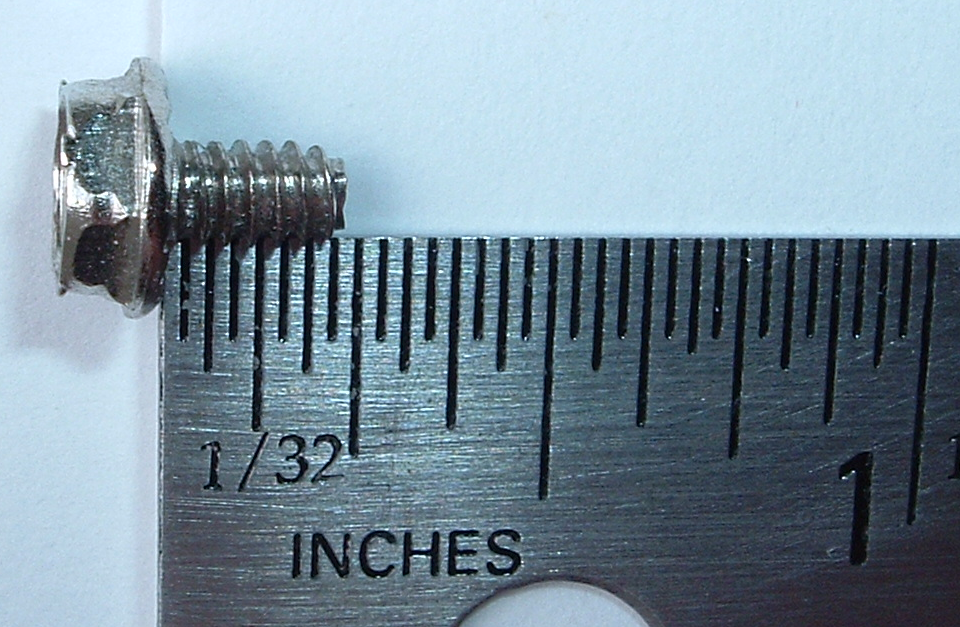
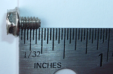 The 6-32 UTS screw has a thread pitch of 1/32 in
The 6-32 is a UTS screw with a major thread diameter of 0.1380 inches and a pitch (distance between adjacent threads) of 1/32 in. It is by far the most common screw found inside computer cases[1] and commonly appears in lengths of 0.15 and 0.25 in. Nearly every brand new computer case comes with a bag of these. They are used:
- To fasten a power supply to the case
- To fasten a hard disk drive to the case
- To hold an expansion card in place by its metal slot cover
- To fasten case components to one another
- Usually, a 6-32 screw holds the main cover on the case. When it's not a 6-32, a larger 8-32 is the most likely alternative.
Of all the screws provided by computer case manufacturers, the 6-32 screw typically has the coarsest threading. They are almost always provided with a Phillips drive, accepting a #2 size tip (the larger of the two most common Phillips screwdriver tips). While a #1 size tip will drive the screw, it will be awkward to use and increases the risk of cam-out and damage to the screw head. They are less frequently provided with a hex head, even less with a pan head - a low disk with a chamfered outer edge. Because they are used in places where easy removal and replacement may be desirable (such as on the side panels of the PC case), they are frequently available as thumbscrews with oversized friction-gripped heads that can be removed with one's fingers rather than with tools.
6-32 screws will fit into holes threaded for M3 screws (the second most common type of screw in PCs), but this will damage the finer M3 threading. Also, when 6-32 screws are screwed into brass M3-threaded motherboard standoffs, the threads tend to become "locked", and the entire motherboard must be removed to separate them.
M3 screw
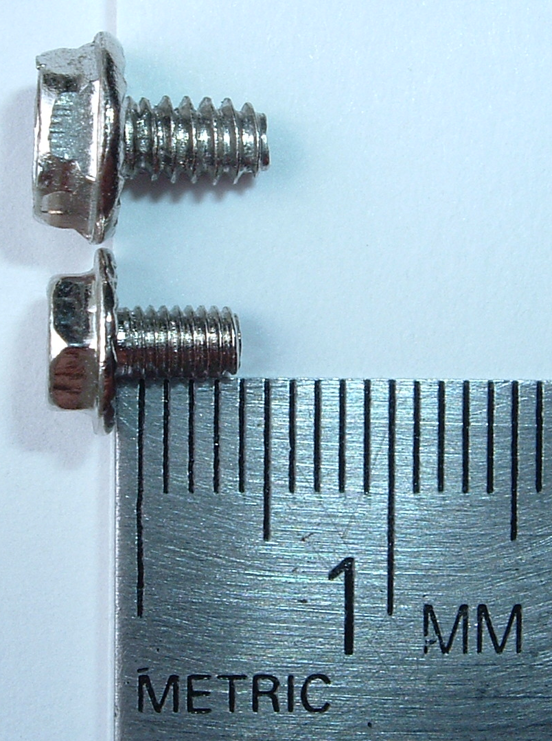
 The M3 screw (center) has a pitch of 0.5 mm, which is finer than the pitch of a 6-32 UTS screw (top).
This screw is the second most common screw found in PCs.[1] This is a metric screw, and just about every case manufacturer provides a package of M3 screws as well as 6-32's. Specifically, the screw type is M3-0.50, meaning the threads of the screws are 0.50 millimetres apart. These screws, like the 6-32 screws, also typically accept a #2 size Phillips screwdriver tip.
M3 screws are used for fastening optical disc drives and floppy drives. They will fit in 6-32-threaded holes, but their narrower diameter and finer thread pitch causes them to seat only loosely in the hole.
M3 screws are also the most common screw used to secure a motherboard to motherboard standoffs.
Of all the screws provided with PCs, M3s are usually identified by them having the finest thread pitch of all the screws provided.[citation needed]
6-32 screws will strip the threads of M3-threaded holes. When the M3 hole is drilled into sheet metal (as on floppy and optical disc drives), a 6-32 screw that damages the threading will typically stay in the hole and can be removed fairly easily. When the M3 threading is into solid metal (such as a motherboard standoff), a 6-32 screw will get stuck before it can be screwed in all the way.
Motherboard standoff
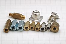 Various types of motherboard standoffs
Most cases use threaded brass male-female standoffs for attaching the motherboard to the case chassis. Sometimes threaded or snap-lock plastic standoffs are used, which are less secure mechanically. Metal standoffs provide an electrical ground connection between the motherboard and case, while plastic standoffs do not. The standoff provides a margin of space between the motherboard and the case. Without the space, the motherboard would be in physical contact with the case, which would cause it to not function because its various solder points would be in contact with the case's metal, which forms a short circuit with the computer's electrical ground.
There is no rigid standard for what measurements a case's standoffs use. However, use of M3 and 6-32 threads is nearly universal.[citation needed] There is also no single standard for the height of the standoff; one quarter inch is common but not universal.
Each standoff has a "male" portion that screws into the case, and a "female" portion that receives a screw that has passed through a specially grounded pre-drilled hole in the motherboard. Standoffs that use strictly M3, strictly 6-32, or a combination (male portion 6-32, female portion M3) are all fairly common.
It is good practice to tighten the standoff to the chassis with a nut driver or pliers, or use a thread locking compound between the male portion of the standoff and the chassis sheet metal. This ensures that if when detaching the motherboard, the screw that holds the motherboard onto the standoff will unfasten instead of the standoff becoming unfastened from the chassis. If tightening the standoff with a nut driver or pliers, be careful not to over-tighten, as the soft metal threads of the standoff and chassis are easily stripped or broken. Using a thread locking compound between the motherboard fastening screw and the female portion of the motherboard standoff is neither needed nor desired. Thread locking compound will not adversely affect the electrical ground path between the motherboard and chassis.
It is a frequent mistake when building PCs to accidentally use 6-32 threaded screws into motherboard standoffs expecting an M3 screw.[citation needed] The result is that the screw will not go all the way, and the threads become stripped and "lock". Once locked, attempts to remove the top screw typically result in the entire standoff unscrewing from the case and potentially flexing the motherboard. In that situation, the screw and the standoff cannot be separated without removing the entire motherboard and subjecting it to potential damage while it is flexed in place.
4-40 jackscrews
Pairs of 4-40 UTS jackscrews are used to fasten certain connectors to hardware ports. The screws are typically located on either side of D-subminiature connectors such as on VGA, serial, parallel, and legacy game controller ports. They are also more recently used on DVI connectors. The female 4-40 is usually just a removable standoff that has been screwed into the port with a relatively tight torque. The standoff can be unscrewed or tightened using a 3/16 inch hex driver. This standoff also often serves as a mechanical mounting either attaching a connector on a flylead to the case or attaching the backplate to an expansion card (connectors on the ATX IO plate are not normally attached to the plate). The screw has 40 threads per inch, and despite its threads appearing similar to M3, they are not interchangeable. Comparing them in SI units, the 4-40 has a pitch of 0.635 mm while the M3 has a finer pitch of 0.5 mm.
A typical length for a 4-40 screw used in PCs is 0.18 in.
Gallery
-

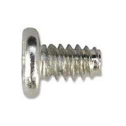
6-32 screw with a pan head, commonly provided in PC cases.
-
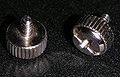
Thumbscrews from an ATX personal computer case
-
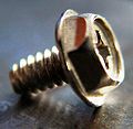
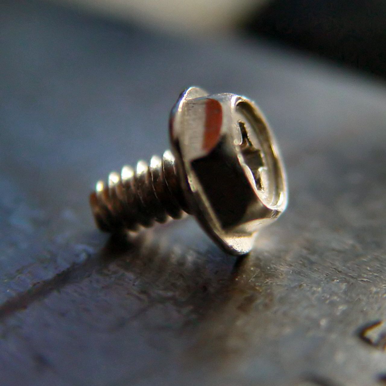
Close-up of a 6-32 screw with a hex cap/Phillips head
References
- McDonough, Andy The 11 Tools Every System Builder Should Own retrieved Nov 21, 2010 from crn.com
- ^ a b Rutter, Daniel Dan's Data - Letters 53, "Screwed", 2006-02-26
Categories:- Computer enclosure
- Screws

Wikimedia Foundation. 2010.