- Mark XIV bomb sight
-
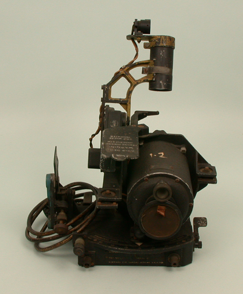
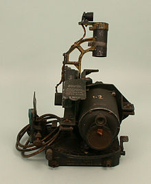 The Mk. XIVA sighting head, which would be mounted in the front of the aircraft and connected to the computor by the cables coiled up on the left. The main features are the gyrostabilizer in the large cylinder, and the collimator on the moving arm that indicated the sighting angle. This example is found in the RAF Museum's reserve collection.
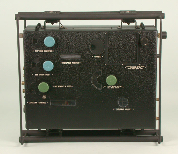
 The Mk. XIVA computor, normally mounted on the left side of the forward fuselage. The wind speed and direction are set on the blue dials, the bomb's terminal velocity and the target altitude on the green dials. Everything else is measured automatically via control inputs seen on the right, and output to the sighting head via the connections on the lower right.
The Mark XIV Computing Bomb Sight is a vector bombsight developed and used by the Royal Air Force's Bomber Command during World War II. The bombsight was also known as the Blackett sight after its primary inventor, P.M.S. Blackett. Production of a slightly modified version was also undertaken in the United States as the Sperry T-1, which was interchangeable with UK-built version.
Developed in 1939, the Mk. XIV started replacing the WWI-era Course Setting Bomb Sight in 1942. The Mk. XIV was essentially an automated version of the Course Setting sight, using a mechanical computer to update the sights in real-time as the aircraft manoeuvred. The Mk. XIV required only 10 seconds of straight flight before the drop, and could account for shallow climbs and dives as well. More importantly, the Mk. XIV sighting unit was much smaller than the Course Setting sight, which allowed it to be mounted on a gyro stabilization platform, dramatically increasing its accuracy and ease of sighting.
The Mk. XIV was theoretically less accurate than the contemporary Norden bombsight, but was smaller, easier to use, much more quick-acting, and better suited for night bombing. It equipped the majority of the RAF's bomber fleet, with a small number of Stabilized Automatic Bomb Sights and Nordens being used in specialist roles.
Contents
History
Course Setting sights
Early bombsights had the problem that they could only correct for the effects of wind in a simple way, and required the bomber to fly directly up or down-wind from the target to minimise the complexity of the required calculations. This made it difficult to attack moving targets, and allowed the anti-aircraft artillery to pre-sight their weapons along the wind line.[1]
In 1917 Harry Wimperis introduced the Course Setting Bomb Sight (CSBS), which replaced the tables and timings with a simple mechanical calculator capable of solving the sideways drift due to wind. As the bomb aimer turned a wind direction knob, the main portion of the sight was pushed to the left or right, indicating the required angle to fly. The CSBS was the first bombsight that allowed the bomber to approach the target from any direction, which offered greatly increased tactical freedom.[2]
The downside to the CSBS was that the settings, made through four main input dials, were useful for only a single given operational setup – a given altitude, heading, etc. If the aircraft manoeuvred, the entire system had to be re-set. Additionally, the system for flying the bomber along the proper line to the target required a time consuming process of trial and error. As the sight was not stabilized, any manoeuvres interfered with this process, any changes further extended the required bomb run. Generally speaking, the CSBS required the bomber to fly straight and level for a lengthy time.[3]
Although the need for an improved CSBS was known in the 1930s, little work on developing such a sight was carried out. That was because an entirely new class of bombsights were being developed, the "tachometric" designs, which offered dramatically improved accuracy while at the same time automating much of the setup. The RAF was working on the Automatic Bomb Sight along these lines, but development was slow and it had not been accepted for use when the war started. Additionally, the Air Ministry had been in extensive negotiations with the US Navy in an effort to gain a licence for the similar Norden bombsight. The Navy constantly refused these requests, based on a number of arguments about secrecy and various political issues.[4]
So as the war started, updated versions of the CSBS, the Mk. VII and Mk. IX, remained universal. A more major upgrade, the Mk. X, was in widespread production and readying for service entry.[5]
A pressing need
On 18 December 1939, Vickers Wellington bombers carried out a raid on German shipping in what would become known as the Air Battle of the Heligoland Bight. Detected on radar and attacked en-route to their targets, the CSBS' demand that they fly straight and level made the bombers easy targets for both fighters and anti-aircraft gunners. Over half the attacking force was destroyed or damaged beyond repair.[3]
On 22 December 1939, at a pre-arranged meeting on bombsight policy, Air Chief Marshal Sir Edgar Ludlow-Hewitt of Bomber Command stated flatly that the CSBS did not meet RAF requirements and asked for a bombsight that would allow the bomber to take any sort of evasive action throughout the bomb run. This, in effect, demanded the use of stabilization in order to allow the bomb aimer to continue making adjustments while the bomber manoeuvred.[3] In other respects the basic operation of the CSBS was considered fine as it was, there was no demand for greatly increased accuracy for instance.
The existing CSBS was clearly not sufficient, nor was the upgraded version, the Mk. X. Both would be difficult to stabilize due to their large size. The Automatic Bomb Sight also lacked stabilization, and it was estimated that it would be some time before it could be added and brought into production. The Norden did offer this feature, but it also required relatively long setup times and was still not available for purchase.[3]
Another solution to the vulnerability of the RAF bombers was to fly at night, which was taken up as the primary goal of Bomber Command from this point on. In this case, the existing sights displayed a number of other problems as well. The Mk. X proved to be very difficult to read at night, and bombers that had received it were quickly re-fit with the earlier Mk. VII or Mk. IX's.[5] The Norden was unable to work at night at all; for setup the bomb aimer had to locate the target long in advance of the drop point using the built-in telescope, at ranges that could not be seen in low-light situations.
What was needed was a new bombsight, one that could be very quickly set up, had useful illumination of the sight so it could be used at night, and was stabilized so the bomb aimer could watch the approach even as the bomber was manoeuvring.[3] An early attempt was the Mk. XI, which mounted a basic drift bar on the front of a gyro unit taken from a Sperry Gyroscope artificial horizon to provide stabilization in the horizontal plane, useful for aiding drift measurements and corrections. However, this also required the range angle to be hand-calculated on the manual Course and Speed Calculator, by no means an easy task. Although introduced in 1941, only a small number were produced.[6][7]
Blackett's solution
The request for a new bombsight was quickly passed onto the Royal Aircraft Establishment where Patrick Blackett of the Aeronautical Research Committee volunteered to lead efforts to produce a replacement.[Notes 1] His solution to the problem was a dramatically updated version of the CSBS concept.
The key advance to the Blackett design was the way the sighting head was aimed. Instead of dialling the parameters into the sight directly, as in the CSBS, these inputs were dialled into a separate console. The console was equipped with repeaters for each of the aircraft instruments needed to operate the sight. The operator then moved the dials on the console so their indicator arrows matched the readings on the instruments. This required so much work that a new crew member, the "bomb-aimers mate", was introduced simply to operate the console.[8]
The inputs drove a mechanical calculator, on the "computor" as it was then spelled.[8] The output of the computor drove flexible shafts that rotated the sight head to the proper angles in azimuth and altitude,[9] representing the wind drift and "range angle". As the sight was physically separated from the console, it was much smaller than the CSBS, and thus was easy to stabilize. The remote console and second operator eliminated the need for the bomb aimer to look away from the sights while on the bomb run.[8]
The sight head itself replaced the older wire crosshairs with a modern reflector sight.[Notes 2] This was stable, fast, easy to operate, and easy to see at night. The resulting Mk. XII bombsight was first tested in September and October 1940, and by the end of October 20 examples had been constructed.[10] A slightly improved version, the Mk. XIII, was also designed, but not put into production.[8]
Mk. XIV
The need for the second crewman was an obvious problem with the Mk. XII, especially as bombers of the era lacked room for the operator.[10] Working with H.J.J. Braddick, Blackett developed a new version of the calculator that included the necessary instruments internally, and took all the measurements and calculations automatically.[8][11] After the initial design was complete, Blackett moved onto other issues with Coastal Command, where he developed his theories of operational research.
The new design reduced the bomb aimer's setup workload to dialling in four settings, settings that did not generally change during the mission. These included the wind direction, wind speed, the height of the target over sea level, and the bomb's terminal velocity, which determined the trail. The altitude, airspeed and course were all measured internally, and presented to the user in windows on the side of the computer case. Once set, the computer could be left alone and automatically updated the aim point, and even displayed this as the "bombing angle" through another window. The computer could even account for steady changes in altitude, allowing the bomb run to take place in a shallow climb of up to 5 degrees, or dive of up to 20 degrees.[12]
The resulting Mk. XIV was first tested in June 1941.[13] It was the first modern bombsight that allowed for accurate bombing immediately after radical manoeuvring, with a settling time as little as 10 seconds. The fast settling time was invaluable during night bombing missions, as it allowed the bomber to fly a helical path, both climbing and turning, and then level out immediately before the drop. Even slow turns made it difficult for night fighters to track the bombers within the limited view of their radar systems, and continually changing altitude is an effective way to avoid anti-aircraft fire.[12]
Although the Mk. XIV was not as accurate as the Norden at altitudes over 20,000 feet, for typical night bombing altitudes between 12 and 16,000 feet, any differences in accuracy were minor. When the need for more accuracy for use with the Tallboy bombs arose in 1943, the Stabilized Automatic Bomb Sight (SABS), a development of the ABS, was introduced in limited numbers.[14] SABS was known as the "precision sight", while the Mk. XIV became the "area sight".
Production and use
Although existing sources do not record when the Mk. XIV went into production in the UK, they do record that operational testing started in January 1942 and production examples started reaching squadrons in March. Its manufacture was done by small machine shops and instrument makers, and production was simply too slow to meet the demand. Between July and October, less than one hundred a month were being delivered. As the design was finalized, automated production was undertaken, and by mid-1943 900 a month were available.[12]
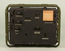 The T-1A computer, a US-built version of the Mk. XIVA computor. This example retains the scales in the reading windows and a blank levelling card, which are missing from the Mk. XIV.
This was enough to equip the heavy bombers as they arrived from the production lines, and by late 1942 the Handley Page Halifax was being delivered with the sight head already installed.[12] To fill demand for other aircraft, and especially smaller ones like the de Havilland Mosquito, the Air Ministry started looking at US manufacturers to supply the bombsight. Frederic Blin Vose of Sperry Gyroscope expressed an interest in the design, and felt he could adapt the Mk. XIV to US production methods and have it in mass production rapidly.[3]
Sperry arranged for A.C Spark Plug to take over manufacture, initially on a sub-contract basis, and later for direct sales to the UK. The two companies then worked in a number of basic changes to the design in order to make it easier to produce, and a final design was ready in May 1942. The Sperry T-1 was fully compatible with UK-built versions, and a T-1 computer could be used with a Mk. XIV sight head, or vice versa. As these started arriving in March 1943, they were sent to light bombers like the Wellington, while UK-built versions were sent to the heavy bombers.[3]
Full production of the T-1 commenced at A.C.'s Flint, MI plant in November 1942. In August 1943, George Mann of A.C. Spark Plug visited the UK for a period of about a year, liaising with RAE Farnborough, Boscombe Down, and the Ministry of Aircraft Production.[3] This led to the T-1A model, which included a cam that adjusted for the difference between indicated and true air speed, eliminating the need for different models for each aircraft.
Later versions
In May 1943, Arthur Travers Harris requested that the maximum bombing altitude be increased from 20 to 30,000 feet, as the Avro Lancaster units were now carrying out missions as high as 22,000 feet. The Air Ministry responded with the Mk. XIVA with a compromise improvement of 25,000 feet and a more accurate angle mechanism,[8] which arrived in December 1944.[15] The A model also introduced the ability for instrument reading differences between aircraft to be set simply by replacing a cam.[8]
The Mk. XIVB and T-1B replaced the suction-powered gyros in the stabilizer with electrical ones, reducing wiring.[8] This was introduced with the 18,000th T-1 on the A.C. production line.[16] By the time production ended in the summer of 1945, 23,450 T-1's of all types had been delivered,[16] along with an unknown number of UK produced Mk. XIV's.
The Mk. XV was a version designed for the Royal Navy and Coastal Command for attacking submarines. As these operations took place at low altitudes, even small changes of altitude air pressure could lead to large errors in the calculation . The Mk. XV allowed the altitude input to be taken directly from a radar altimeter, eliminating these inaccuracies and any instrument lag.[8] The Mk. XVII was a Mk. XV modified for the very high speeds of the Naval Mosquito, allowing attack speeds of more than 400 mph. As the Naval Mosquito did not have a bomb aimer's position, the sight head was unstabilized and mounted in front of the pilot.[8]
In the post-war era, the UK produced derivatives of the design based on the T-1, as opposed to the original Mk. XIV. These T-2 and T-4 designs had much higher altitudes, airspeed and wind speed settings, suitable for high altitude bombing in the jet stream.[3] These could also be used with the Green Satin radar. However, most wartime optical sights like the Mk. XIV proved almost useless for operations in jet aircraft, as the limited distances visible through the sight from high altitudes made it almost impossible to aim before the aircraft had already passed the drop point. Optical bombing quickly gave way to radar bombing, although the Mk. XIV remained in RAF service until 1965.[17]
Description
Basic mechanism
The Mk. XIV consisted of two independent parts, the "sighting head" and the "computor".[18] The sighting head was located in the bomb aimer's window at the front of the aircraft. The separate computer cabinet was assembled with the operating knobs positioned on the right side of the case, so it had to be placed on the left side of the fuselage. The two were connected via two flexible cable drives.
The computor cabinet included only four main controls. On the left side of the chassis, from top to bottom, were dials that set the wind direction, wind speed, and the bomb's terminal velocity. All of these inputs were set by reading their value in a small window on the left side of the dials. Additional windows provided output values for the indicated airspeed, course, and the bombing angle (or range angle).[19] Clips in the upper right held a card with levelling data, as well as notes about the sight or the bombs being dropped. The computor was also connected to several external sources. Compressed air was supplied from the engines to drive the mechanism, and an exhaust allowed the less dense air to escape. Tubes were also connected to the pitot tube and static air source, which allowed the accurate measurement of airspeed. A separate electrical connections input the direction measured on the "distant reading" compass, using a selsyn.[20]
The sight head was mounted from the bottom on a square platform, with screw adjustments that could be used to level the platform. Above the mounting platform was stabilization gyro, which moved the entire upper section of the system in relation to the mounting platform below. As the sights worked by reflecting light off a mirror in the center, motion of the mirror would result in twice the motion of the aim point. To address this, the gyro was attached through levers with a 2-to-1 reduction.[9][21] The reflector sight mechanism was mounted on the left front of the gyro. A metal flap protected the half-mirror from damage, and was rotated rearward for use, then covering the spirit level instead. The collimator was mounted on a prominent arm that projected in front of the sight when in use, and folded forward when stored. Electrical power was provided to light the collimator as well as the "drift scale", which indicated the angle to fly to correct for the wind drift.[22]
Operation
The main design feature of the Mk. XIV was that it gave the bomb aimer more time to work on the problem of bringing the aircraft to the proper location to drop the bombs. As the calculations of this location were being carried out automatically, he could concentrate solely on the sight throughout the bomb run. The sight projected a crosshairs into space so it appeared to be projected on the ground, allowing the user to focus on the target throughout.[23]
The vertical line on the sight was relatively short, and could not be used directly to measure drift – unlike the long drift wires of the CSBS it replaced. To address this, the "collimator handle" could be used to manually rotate the sighting assembly forward, allowing the bomb aimer to point the sight further in front of the aircraft's location in order to ensure the vertical line passed through the target. When the handle is returned to the resting position and released, the shaft to the computor automatically re-engaged.[24] The handle was also used to rotate the collimator forward for storage.
Many of the figures used in the calculation of the bomb's trajectory were based on fixed values, and were entered before the mission started. In particular, the terminal velocity is based on the type of bomb being dropped and will not change during the mission. This is used to calculate how steep the path of the bomb will be when dropped from high altitudes; at lower altitudes and airspeeds, the bomb did not reach terminal velocity and followed a more parabolic path. Other measures were entered only once as the aircraft approached the target.[25]
Measuring wind
The only major measurement that could not be made automatically or before the mission was the determination of the windspeed and direction. These change over time, and especially due to changes in location or altitude (see thermal wind), which required an accurate determination of the wind in the general area of the target, and would generally be inaccurate if dialled at at the mission start. Taking this measurement while nearing the target was an important procedure on the CSBS, which included a number of methods of determining the wind.[26] In the case of the Mk. XIV, the manual describes only one method of determining the wind, the most complex of the procedures from the CSBS model.
Prior to the bomb run the pilot is directed to fly the aircraft in several different directions in sequence, preferably set at 120 degrees apart. On each leg, the bomb aimer uses the reticle to measure the drift angle, either by rotating the wind direction dial to turn the sight head, or by unlocking the azimuth control from the computer and turning the sight manually.[27] In either case the angle of the aircraft and the angle of the drift (measured either from the dial on the computer or the scale on the sight) is recorded. Using the Mk. III Navigation Computor, the RAF's version of the modern E6B, the three sets of angles are entered onto the wind calculator face. This normally results in a small triangular area forming where the three lines meet, and the center of this triangle reveals the wind speed and direction. This value is then entered onto the computer.[28]
Other details
As the Mk. XIV included the ability to calculate the effects of a shallow climb or dive (or "glide" as it is referred to in bombing), the computer included its own levelling mechanism. This was added to the range angle calculated by the computer in order to move the sight head. Levelling the system required adjustment of both the computer and the sight head. Since these were in a fixed relationship to each other, levelling could be carried out on the ground and then left alone. Any adjustments required were recorded on a card fixed to the front of the computer.[29] In contrast, the CSBS was held at a fixed angle to the aircraft fuselage, and required constant adjustment whenever the aircraft angle of attack changed, which it did with every increase or decrease of airspeed.
As the computer held the level line and was sending angle commands to the sight, this eliminated the need for a two-axis gyro in the sighting head itself. The gyro on the sight head only adjusted for rotation of the aircraft around its roll axis.[30] Separate levelling of the sight head was so rare that the spirit level was normally covered by a metal plate to protect it from damage. The normally periodic and minor changes to level that the sighting head required could be accomplished by removing the cover over the level and then turning a small adjusting screw on the mount. Pressing the release lever unlocked the sighting head from the mounting shaft, allowing the sight to be removed and then re-attached simply by sliding it back onto the shaft, maintaining the level setting between missions.[22]
The bomb sight was also supplied with the Emergency Computor, a simple circular slide rule for use when the main computer stopped working.[12] In this case the bomb aimer would dial in the same basic parameters on the various disks, and read out the proper sighting angle at the bottom.[31] Wind had to be estimated and calculated by hand. The angles were then entered manually into the sight; the drive cables were clutched out, the aiming angle entered using the operating handle, and the drift angle set by a small locking screw.
A separate "switchbox" was used to control the brightness of the lamps driving the drift scale and reticle.[32]
See also
- Norden Bombsight a similar vintage USAAF bomb sight
- Stabilizing Automatic Bomb Sight a contemporary bomb sight used for precision bombing by the RAF
References
Notes
Citations
- ^ Goulter 1995, p. 28.
- ^ Goulter 1995, p. 27.
- ^ a b c d e f g h i Black 2001b.
- ^ David Zimmerman, "Top Secret Exchange: the Tizard Mission and the Scientific War", McGill-Queen's Press, 1996, pp. 34–60
- ^ a b Black 2001a.
- ^ SD719 1952, p. 283.
- ^ An image of the Mk. XI is available at this page.
- ^ a b c d e f g h i j SD719 1952, p. 284.
- ^ a b Hore 2003, p. 89.
- ^ a b Hore 2003, p. 90.
- ^ Hore 2003, pp. 90–91.
- ^ a b c d e Harris 1995, p. 100.
- ^ Hore 2003, p. 91.
- ^ "Royal Air Force Bomber Command 60th Anniversary Campaign Diary November 1943: 11/12"
- ^ Harris 1995, p. 101.
- ^ a b "Bombsights, Types T-1A and T-1B", (US) Army Air Forces, p. 1
- ^ Maurice Kirby, "Operational Research in War and Peace", Imperial College Press, 2003, pg. 91
- ^ AP1730 1943, Chapter 9 §6.
- ^ AP1730 1943, Chapter 9 Figure 4.
- ^ AP1730 1943, Chapter 9 Figure 5.
- ^ AP1730 1943, Chapter 9 §11.
- ^ a b AP1730 1943, Chapter 9 Figure 6.
- ^ AP1730 1943, Chapter 9 §7.
- ^ AP1730 1943, Chapter 9 §9.
- ^ AP1730 1943, §8.
- ^ AP1730 1943, Chapter 4 §65–94.
- ^ AP1730 1943, Chapter 9 §43.
- ^ AP1730 1943, Chapter 9 §44.
- ^ AP1730 1943, Chapter 9 §iii.
- ^ AP1730 1943, Chapter 9 Figure 9.
- ^ See image here.
- ^ AP1730 1943, Chapter 4 §13.
Bibliography
- Christina Goulter, "A forgotten offensive: Royal Air Force Coastal Command's anti-shipping campaign, 1940–1945", Routledge, 1995
- Peter Hore, "Patrick Blackett: Sailor, Scientist, and Socialist", Psychology Press, 2003
- Henry Black, "Major Bomb Sights Used in WW2 by RAF Bomber Command", 2001(a)
- Henry Black, "The T1- Bomb Sight Story", 26 July 2001(b)
- Sir Arthur Travers Harris, "Despatch on war operations, 23rd February, 1942, to 8th May, 1945", Routledge, 1995
- SD719, "Armament, Volume I; Bombs and Bombing Equipment", Air Ministry, 1952
- AP1730, "Air Publication A.P.1730A, Volume 1: Bomb Sights", Air Ministry, 1943
- Volta Torrey, "How the Norden Bombsight Does Its Job", Popular Science, June 1945, pp. 70–73, 220, 224, 228, 232
Categories:- Optical bombsights

Wikimedia Foundation. 2010.