- Microwave cavity
-
A microwave cavity is a closed metal structure that confines electromagnetic fields in the microwave region of the spectrum. Such cavities act as resonant circuits with extremely low loss at their frequency of operation. Their Q factor may reach several million compared to a few hundred for resonant circuits made with inductors and capacitors at the same frequency.
Contents
Theory of Operation
Resonant cavities are usually made from closed (or short-circuited) sections of waveguide or high-permittivity dielectric material (see dielectric resonator). Electric and magnetic energy is stored in the cavity and the only losses are due to finite conductivity of cavity walls and dielectric losses of material filling the cavity. Every cavity has numerous resonant frequencies that correspond to electromagnetic field modes satisfying necessary boundary conditions on the walls of the cavity. Because of these boundary conditions that must be satisfied at resonance (tangential electric fields must be zero at cavity walls), it follows that cavity length must be an integer multiple of half-wavelength at resonance.[1] Hence, a resonant cavity can be thought of as a waveguide equivalent of short circuited half-wavelength transmission line resonator.[2] Q factor of a resonant cavity can be calculated using cavity perturbation theory and expressions for stored electric and magnetic energy.
The electromagnetic fields in the cavity are excited via external coupling. An external power source is usually coupled to the cavity by a small aperture, a small wire probe or a loop.[3] External coupling structure has an effect on cavity performance and needs to be considered in the overall analysis.[4]
Rectangular Microwave Cavity
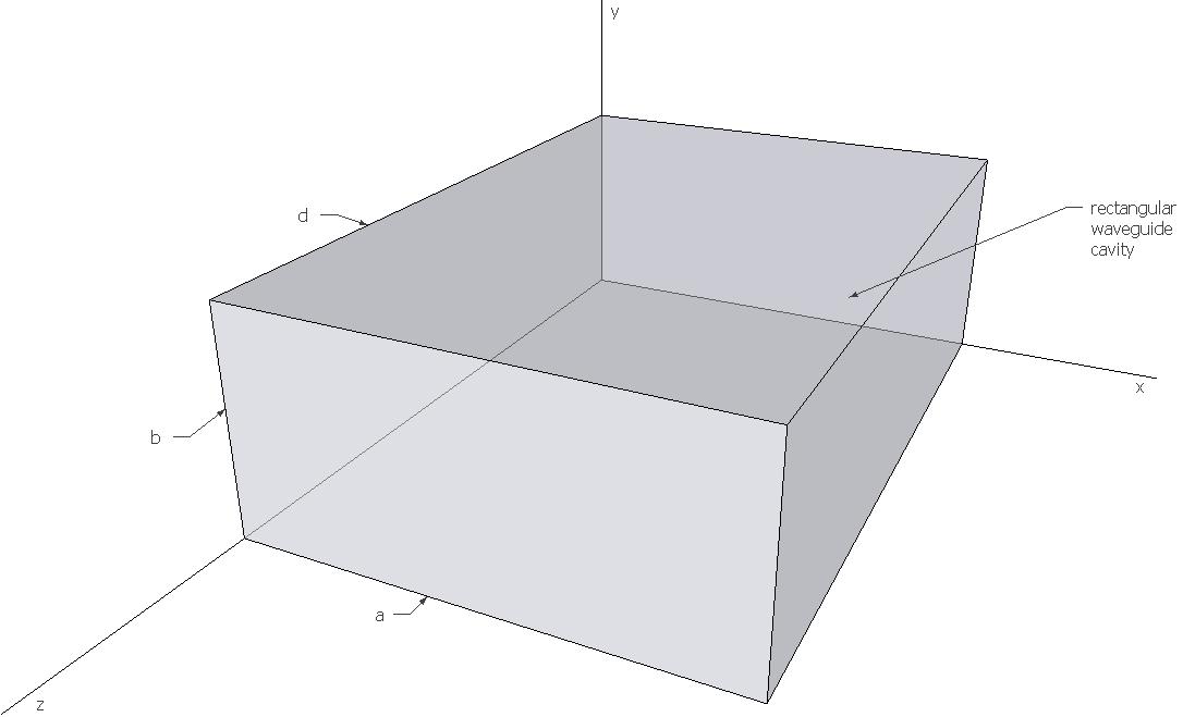
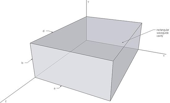 Rectangular cavity
Resonant frequency of a rectangular microwave cavity for any TEmnl or TMmnl resonant mode can be found by imposing boundary conditions on electromagnetic field expressions. This frequency is given by[5]:
-

(
where kmnl is the wavenumber, c is the speed of light in vacuum, and μr and
 are relative permeability and permittivity respectively.
Q factor of rectangular microwave cavity can be decomposed in two parts. First part is Qc, the Q factor of the cavity with lossy walls filled with lossless dielectric, and the second part is Qd, the Q factor of the cavity with perfectly conducting wall filled with lossy dielectric. Total Q factor of the cavity can be found as[6]:
-

(
Qc and Qd are calculated as follows:
-

(
-

(
where k is the wavenumber, η is the intrinsic impedance of the dielectric, Rs is the surface resistivity of the cavity walls, μr and
are relative permeability and permittivity respectively and tanδ is the loss tangent of the dielectric.Comparison to LC Circuits
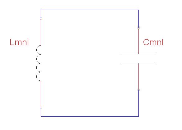
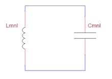 LC circuit equivalent for microwave resonant cavity
Microwave resonant cavities can be represented and thought of as simple LC circuits.[7] For a microwave cavity, the stored electric energy is equal to the stored magnetic energy at resonance as is the case for a resonant LC circuit. In terms of inductance and capacitance, the resonant frequency for a given mnl mode can be written as[8]:
-

(
-

(
-

(
where V is the cavity volume, kmnl is the mode wavenumber and
 and μ are permittivity and permeability respectively.
To better understand the utility of resonant cavities at microwave frequencies, it is useful to note that the losses of conventional inductors and capacitors start to increase with frequency in the VHF range. Similarly, for frequencies above one gigahertz, Q factor values for transmission-line resonators start to decrease with frequency.[9] Because of their low losses and high Q factors, cavity resonators are preferred over conventional LC and transmission-line resonators at high frequencies.
Losses in LC Resonant Circuits
Conventional inductors are usually wound from wire in the shape of a helix with no core. Skin effect causes the high frequency resistance of inductors to be many times their direct current resistance. In addition, capacitance between turns causes dielectric losses in the insulation which coats the wires. These effects make the high frequency resistance greater and decrease the Q factor.
Conventional capacitors use air, mica, ceramic or perhaps teflon for a dielectric. Even with a low loss dielectric, capacitors are also subject to skin effect losses in their leads and plates. Both effects increase their equivalent series resistance and reduce their Q.
Even if the Q factor of VHF inductors and capacitors is high enough to be useful, their parasitic properties can significantly affect their performance in this frequency range. The shunt capacitance of an inductor may be more significant than its desirable series inductance. The series inductance of a capacitor may be more significant than its desirable shunt capacitance. As a result, in the VHF or microwave regions, a capacititor may appear to be an inductor and an inductor may appear to be a capacitor. These phenomena are better known as parasitic inductance and parasitic capacitance.
Losses in Cavity Resonators
Dielectric loss of air is extremely low for high frequency electric or magnetic fields. Air-filled microwave cavities confine electric and magnetic fields to the air spaces between their walls. Electric losses in such cavities are almost exclusively due to currents flowing in cavity walls. While losses from wall currents are small, cavities are frequently plated with silver to increase their electrical conductivity and reduce these losses even further. Copper cavities frequently oxidize, which increases their loss. Silver or gold plating prevents oxidation and reduces electrical losses in cavity walls. Even though gold is not quite as good a conductor as copper, it still prevents oxidation and the resulting deterioration of Q factor over time. However, because of its high cost, it is used only in the most demanding applications.
Some satellite resonators are silver plated and covered with a gold flash layer. The current then mostly flows in the high-conductivity silver layer, while the gold flash layer protects the silver layer from oxidizing.
Notes
- ^ David Pozar, Microwave Engineering, 2nd edition, Wiley, New York, NY, 1998.
- ^ David Pozar, Microwave Engineering, 2nd edition, Wiley, New York, NY, 1998.
- ^ R. E. Collin, Foundations for Microwave Engineering, 2nd edition, IEEE Press, New York, NY, 2001.
- ^ Montgomery, C. G. & Dicke, Robert H. & Edward M. Purcell, Principles of microwave circuits / edited by C.G. Montgomery, R.H. Dicke, E.M. Purcell, Peter Peregrinus on behalf of the Institution of Electrical Engineers, London, U.K., 1987.
- ^ David Pozar, Microwave Engineering, 2nd edition, Wiley, New York, NY, 1998.
- ^ David Pozar, Microwave Engineering, 2nd edition, Wiley, New York, NY, 1998.
- ^ Montgomery, C. G. & Dicke, Robert H. & Edward M. Purcell, Principles of microwave circuits / edited by C.G. Montgomery, R.H. Dicke, E.M. Purcell, Peter Peregrinus on behalf of the Institution of Electrical Engineers, London, U.K., 1987.
- ^ Montgomery, C. G. & Dicke, Robert H. & Edward M. Purcell, Principles of microwave circuits / edited by C.G. Montgomery, R.H. Dicke, E.M. Purcell, Peter Peregrinus on behalf of the Institution of Electrical Engineers, London, U.K., 1987.
- ^ R. E. Collin, Foundations for Microwave Engineering, 2nd edition, IEEE Press, New York, NY, 2001.
References
- David Pozar, Microwave Engineering, 2nd edition, Wiley, New York, NY, 1998.
- Montgomery, C. G. & Dicke, Robert H. & Edward M. Purcell, Principles of microwave circuits / edited by C.G. Montgomery, R.H. Dicke, E.M. Purcell, Peter Peregrinus on behalf of the Institution of Electrical Engineers, London, U.K., 1987.
- R. E. Collin, Foundations for Microwave Engineering, 2nd edition, IEEE Press, New York, NY, 2001.
Categories:- Microwave technology
-
Wikimedia Foundation. 2010.