- Strain gauge
-
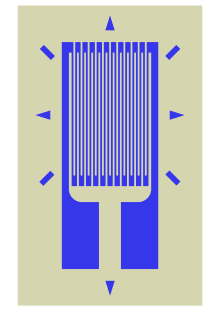 Typical foil strain gauge. The gauge is far more sensitive to strain in the vertical direction than in the horizontal direction. The markings outside the active area help to align the gauge during installation.
A strain gauge (also strain gage) is a device used to measure the strain of an object. Invented by Edward E. Simmons and Arthur C. Ruge in 1938, the most common type of strain gauge consists of an insulating flexible backing which supports a metallic foil pattern. The gauge is attached to the object by a suitable adhesive, such as cyanoacrylate.[1] As the object is deformed, the foil is deformed, causing its electrical resistance to change. This resistance change, usually measured using a Wheatstone bridge, is related to the strain by the quantity known as the gauge factor.
Contents
Physical operation
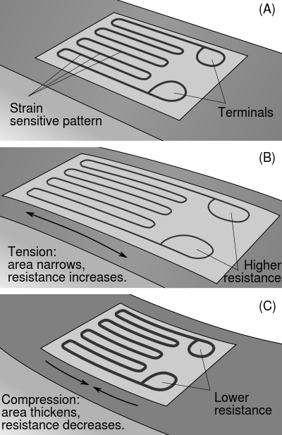
A strain gauge takes advantage of the physical property of electrical conductance and its dependence on not merely the electrical conductivity of a conductor, which is not only the property of its material, but also the conductor's geometry. When an electrical conductor is stretched within the limits of its elasticity such that it does not break or permanently deform, it will become narrower and longer, changes that increase its electrical resistance end-to-end. Conversely, when a conductor is compressed such that it does not buckle, it will broaden and shorten, changes that decrease its electrical resistance end-to-end. From the measured electrical resistance of the strain gauge, the amount of applied stress may be inferred. A typical strain gauge arranges a long, thin conductive strip in a zig-zag pattern of parallel lines such that a small amount of stress in the direction of the orientation of the parallel lines results in a multiplicatively larger strain over the effective length of the conductor—and hence a multiplicatively larger change in resistance—than would be observed with a single straight-line conductive wire. Strain gauges measure only local deformations and can be manufactured small enough to allow a "finite element" like analysis of the stresses to which the specimen is subject. This can be positively used in fatigue studies of materials.
Gauge factor
The gauge factor GF is defined as:
where
- ΔR is the change in resistance caused by strain,
- RG is the resistance of the undeformed gauge, and
 is strain.
For metallic foil gauges, the gauge factor is usually a little over 2.[2] For a single active gauge and three dummy resistors, the output v from the bridge is:
where
- BV is the bridge excitation voltage.
Foil gauges typically have active areas of about 2–10 mm2 in size. With careful installation, the correct gauge, and the correct adhesive, strains up to at least 10% can be measured.
Gauges in practice
 Visualization of the working concept behind the strain gauge on a beam under exaggerated bending.File:Beam.jpgbeam under exaggerated bending.
An excitation voltage is applied to input leads of the gauge network, and a voltage reading is taken from the output leads. Typical input voltages are 5 V or 12 V and typical output readings are in millivolts.Foil strain gauges are used in many situations. Different applications place different requirements on the gauge. In most cases the orientation of the strain gauge is significant.
Gauges attached to a load cell would normally be expected to remain stable over a period of years, if not decades; while those used to measure response in a dynamic experiment may only need to remain attached to the object for a few days, be energized for less than an hour, and operate for less than a second.
Strain gauges are attached to the substrate with a special glue. The type of glue depends on the required lifetime of the measurement system. For short term measurements (up to some weeks) cyanoacrylic glue is appropriate, for long lasting installation epoxy glue is required. Usually epoxy glue requires high temperature curing (at about 80-100°C). The preparation of the surface where the strain gauge is to be glued is of the utmost importance. The surface must be smoothed (e.g. with very thin sand paper), deoiled with solvents, the solvent traces must then be removed and the strain gauge must be glued immediately after this to avoid oxidation or pollution of the prepared area. If these steps are not followed the strain gauge binding to the surface may be unreliable and unpredictable measurement errors may be generated.
Strain gauge based technology is utilized commonly in the manufacture of pressure sensors. The gauges used in pressure sensors themselves are commonly made from silicon, polysilicon, metal film, thick film, and bonded foil.
Variations in temperature
Variations in temperature will cause a multitude of effects. The object will change in size by thermal expansion, which will be detected as a strain by the gauge. Resistance of the gauge will change, and resistance of the connecting wires will change.
Most strain gauges are made from a constantan alloy.[3] Various constantan alloys and Karma alloys have been designed so that the temperature effects on the resistance of the strain gauge itself cancel out the resistance change of the gauge due to the thermal expansion of the object under test. Because different materials have different amounts of thermal expansion, self-temperature compensation (STC) requires selecting a particular alloy matched to the material of the object under test.
Strain gauges that are not self-temperature-compensated (such as isoelastic alloy) can be temperature compensated by use of the dummy gauge technique. A dummy gauge (identical to the active strain gauge) is installed on an unstrained sample of the same material as the test specimen. The sample with the dummy gauge is placed in thermal contact with the test specimen, adjacent to the active gauge. The dummy gauge is wired into a Wheatstone bridge on an adjacent arm to the active gauge so that the temperature effects on the active and dummy gauges cancel each other.[4] (Murphy's Law was originally coined in response to a set of gauges being incorrectly wired into a Wheatstone bridge.[5])
Temperature effects on the lead wires can be cancelled by using a "3-wire bridge" or a "4-wire ohm circuit"[6] (also called a "4-wire Kelvin connection").
In any case it is a good engineering practice to keep the Wheatstone bridge voltage drive low enough to avoid the self heating of the strain gauge. The self heating of the strain gauge depends on its mechanical characteristic (large strain gauges are less prone to self heating). Low voltage drive levels of the bridge anyway reduce the sensitivity of the overall system.
Errors and compensation
Zero Offset - If the impedance of the four gauge arms are not exactly the same after bonding the gauge to the force collector, there will be a zero offset which can be compensated by introducing a parallel resistor to one or more of the gauge arms.
Temperature coefficient of Gauge Factor (TCGF) - This is the change of sensitivity of the device to strain with change in temperature. This is generally compensated for by the introduction of a fixed resistance in the input leg, whereby the effective supplied voltage will increase with temperature, compensating for the decrease in sensitivity with temperature.
Zero Shift with temperature - If the TCGF of each gage is not the same, there will be a zero shift with temperature. This is also caused by anomalies in the force collector. This is usually compensated for with one or more resistors strategically placed in the compensation network.
Linearity - This is an error whereby the sensitivity changes across the pressure range. This is commonly a function of the force collection thickness selection for the intended pressure and/or the quality of the bonding.
Hysteresis - This is an error of return to zero after pressure excursion.
Repeatability - This error is sometimes tied-in with hysteresis but is across the pressure range.
EMI induced errors - As strain gauges output voltage is in the mV range, even uV if the Wheatstone bridge voltage drive is kept low to avoid self heating of the element, special care must be taken in output signal amplification to avoid amplifing also the superimposed noise. A solution which is frequently adopted is to use "carrier frequency" amplifiers which convert the voltage variation into a frequency variation (as in VCOs) and have a narrow bandwidth thus reducing out of band EMI.
Overloading - If a strain gauge is loaded beyond its design limit (measured in microstrains) its performance degrades and can not be recovered. Normally good engineering practice suggests not to stress strain gauges beyond +/-3000 microstrains.
Humidity - If the wires connecting the strain gauge to the signal conditioner are not protected against humidity (bare wire) a parasitic resistance creates between the wires and the substrate to which the strain gauge is glued, or between the two wires themselves. This resistance introduces an error which is proportional to the resistance of the strain gauge. For this reason low resistance strain gauges (120 ohm) are less prone to this type of error. To avoid this error it is sufficient to protect the strain gauges wires with insulating enamel (e.g., epoxy or polyurethanic type). Strain gauges with unprotected wires may be used only in a dry laboratory environment but not in an industrial one.
Other gauge types
For measurements of small strain, semiconductor strain gauges, so called piezoresistors, are often preferred over foil gauges. A semiconductor gauge usually has a larger gauge factor than a foil gauge. Semiconductor gauges tend to be more expensive, more sensitive to temperature changes, and are more fragile than foil gauges.
In biological measurements, especially blood flow / tissue swelling, a variant called mercury-in-rubber strain gauge is used. This kind of strain gauge consists of a small amount of liquid mercury enclosed in a small rubber tube, which is applied around e.g., a toe or leg. Swelling of the body part results in stretching of the tube, making it both longer and thinner, which increases electrical resistance.
Fiber optic sensing can be employed to measure strain along an optical fiber. Measurements can be distributed along the fiber, or taken at predetermined points on the fiber. The 2010 America's Cup boats Alinghi 5 and USA-17 both employ embedded sensors of this type [1].
Capacitive strain gauges use a variable capacitor to indicate the level of mechanical deformation.
Vibrating wire strain gauges are used in Geotechnical and Civil Engineering applications. The gauge consists of a vibrating, tensioned wire. The strain is calculated by measuring the resonant frequency of the wire (an increase in tension increases the resonant frequency).
Mechanical types
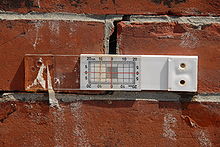 Mechanical strain gauge used to measure the growth of a crack in a masonry foundation. This one is installed on the Hudson-Athens Lighthouse
Simple mechanical types (such as illustrated to the left) are used in civil engineering to measure movement of buildings, foundations, and other structures. In the illustrated example, the two halves of the device are rigidly attached to the foundation wall on opposite sides of the crack. The red reference lines are on the transparent half and the grid is on the opaque white half. Both vertical and horizontal movement can be monitored over time. In this picture, the crack can be seen to have widened by approximately 0.3 mm (with no vertical movement) since the gauge was installed.
More sophisticated mechanical types incorporate dial indicators and mechanisms to compensate for temperature changes. These types can measure movements as small as 0.002 mm.[7]
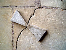 Two marble triangles marked 19-1-07 and a crack in Sagrada Familia inner wall. That is probably the most basic device to monitor wall movement
See also
References
- ^ Strain Gage: Materials
- ^ Strain Gage: Sensitivity
- ^ Constantan Alloy: Strain Gauge Selection
- ^ Shull, Larry C., "Basic Circuits", Hannah, R.L. and Reed, S.E. (Eds.) (1992).Strain Gage Users' Manual, p. 122. Society for Experimental Mechanics. ISBN 0-912053-36-4.
- ^ Spark, N. (2006). A History of Murphy's Law. Periscope Film. ISBN 978-0-9786388-9-4
- ^ The Strain Gage
- ^ Mastrad Quality and Test Systems web site
External links
Categories:- Sensors
- Elasticity (physics)


Wikimedia Foundation. 2010.