- Frequency comb
-
A frequency comb is the graphic representation of the spectrum of a mode locked laser. An octave spanning comb can be used for mapping radio frequencies into the optical frequency range or it can be used to steer a piezoelectric mirror within a carrier envelope phase correcting feedback loop. (It should not be confused with mono-mode laser frequency stabilization as mode-locking requires multi-mode lasers.)
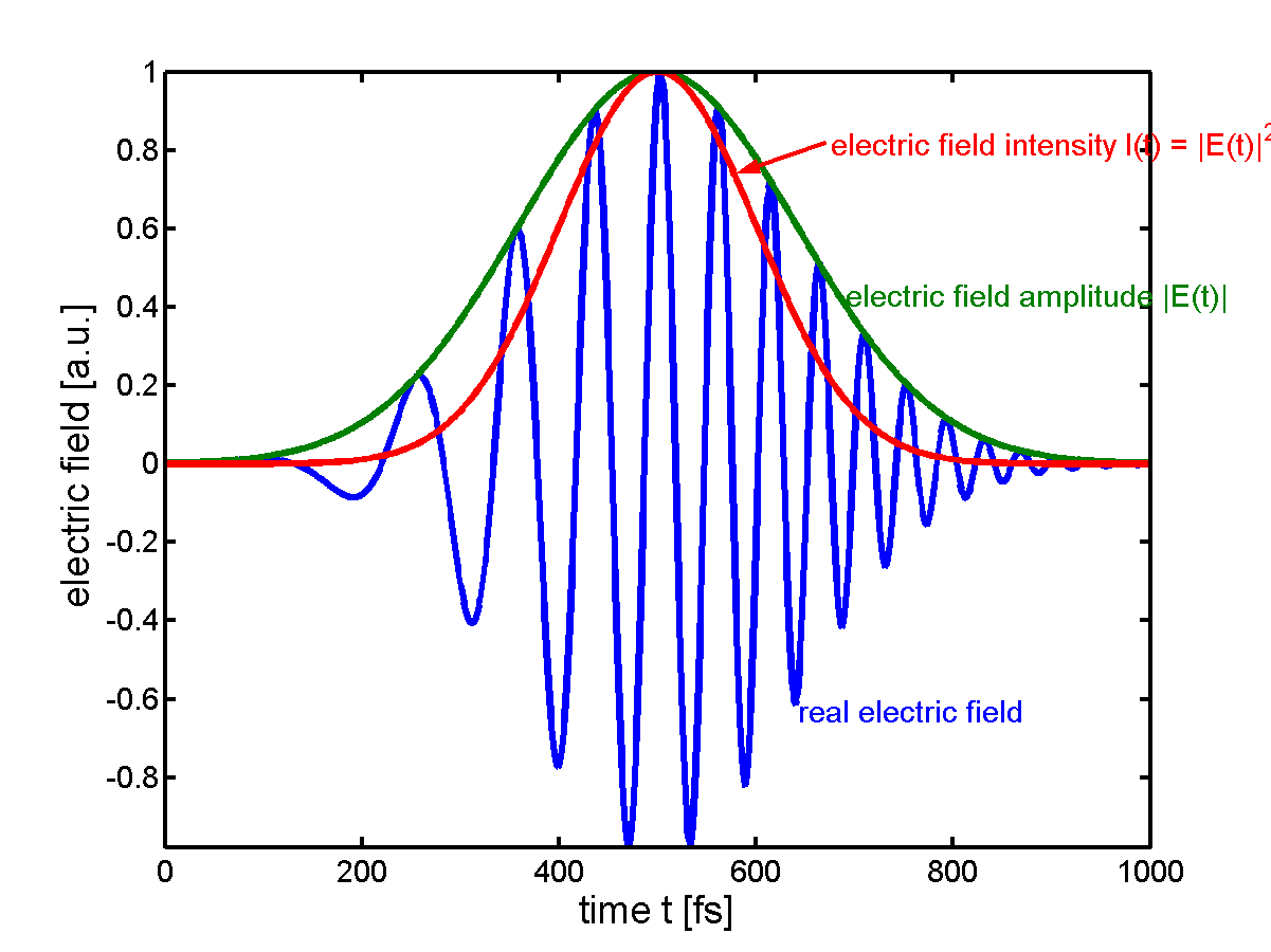
 An ultrashort pulse of light in the time domain. In this figure, the amplitude and intensity are Gaussian functions. Note how the author chooses to set the maximum of the function into the maximum of the envelope.
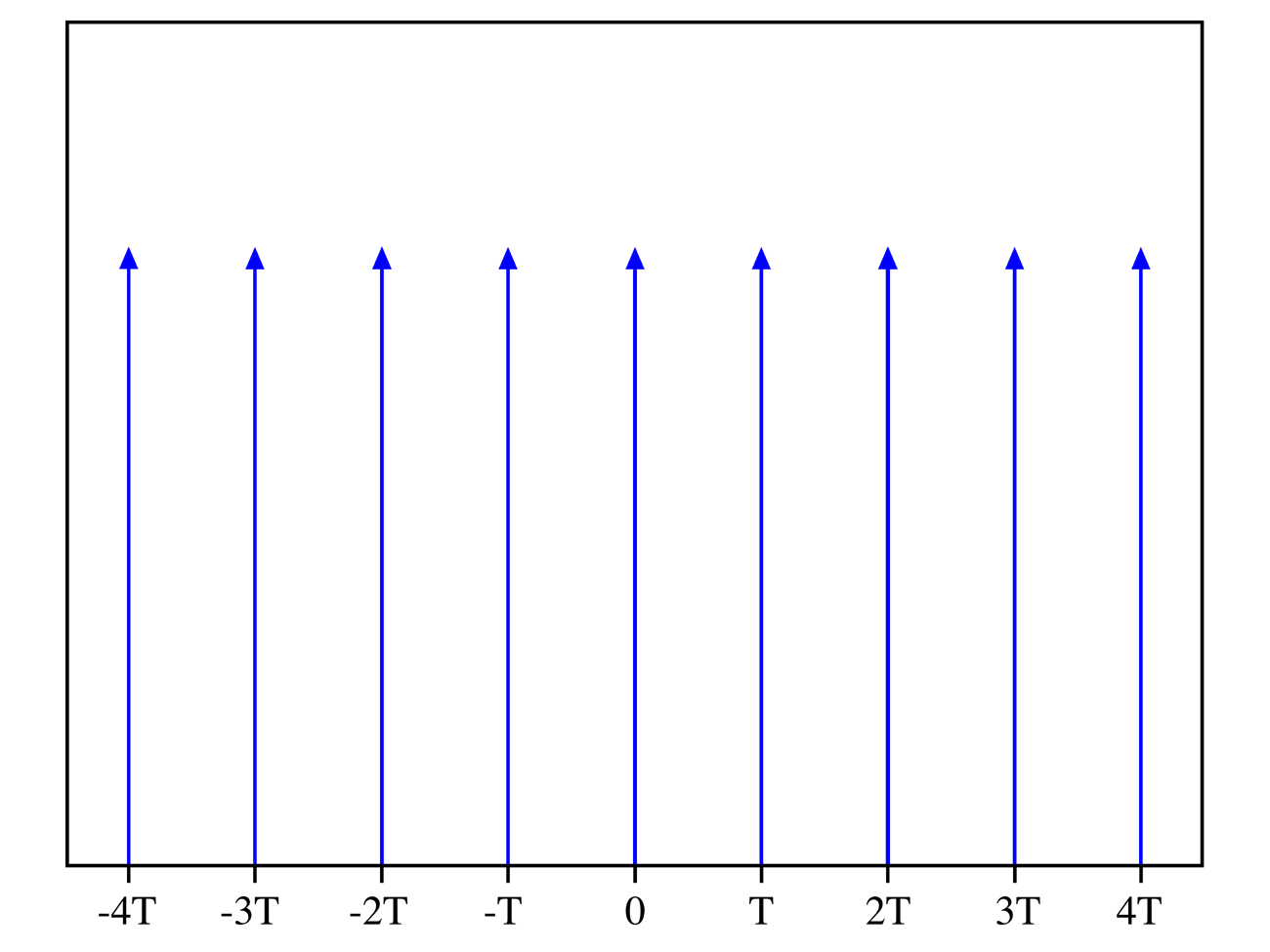
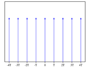 A Dirac comb is an infinite series of Dirac delta functions spaced at intervals of T.
Contents
Frequency comb generation
Modelocked lasers produce a series of optical pulses separated in time by the round-trip time of the laser cavity. The spectrum of such a pulse train is a series of Dirac delta functions separated by the repetition rate (the inverse of the round trip time) of the laser. This series of sharp spectral lines is called a frequency comb or a frequency Dirac comb.
A purely electronic device, which generates a series of pulses, also generates a frequency comb. These are produced for electronic sampling oscilloscopes, but also used for frequency comparison of microwaves, because they reach up to 1 THz. Since they include 0 Hz they do not need the tricks which make up the rest of this article.
Frequency comb widening to one octave
To be usable, the comb must be widened to at least an octave: that is, the highest-frequency must be at least double the lowest frequency. One of three techniques may be used:
- supercontinuum generation by strong self-phase modulation in nonlinear photonic crystal fiber
- a Ti:sapphire laser using intracavity self-phase modulation
- the second harmonic can be generated in a long crystal so that by consecutive sum frequency generation and difference frequency generation the spectrum of first and second harmonic widens until they overlap.
Carrier-envelope offset measurement
Each line is displaced from a harmonic of the repetition rate by the carrier-envelope offset frequency. The carrier-envelope offset frequency is the rate at which the peak of the carrier frequency slips from the peak of the pulse envelope on a pulse-to-pulse basis.
Measurement of the carrier-envelope offset frequency is usually done with a self-referencing technique, in which the phase of one part of the spectrum is compared to its harmonic.
In the 'frequency − 2 × frequency' technique, light at the lower energy side of the broadened spectrum is doubled using second harmonic generation in a nonlinear crystal and a heterodyne beat is generated between that and light at the same wavelength on the upper energy side of the spectrum. This beat frequency, detectable with a photodiode, is the carrier-envelope offset frequency.
Alternatively, from light at the higher energy side of the broadened spectrum the frequency at the peak of the spectrum is subtracted in a nonlinear crystal and a heterodyne beat is generated between that and light at the same wavelength on the lower energy side of the spectrum. This beat frequency, detectable with a photodiode, is the carrier-envelope offset frequency.
Because the phase is measured directly and not the frequency, it is possible to set the frequency to zero and additionally lock the phase, but because the intensity of the laser and this detector is not very stable, and because the whole spectrum beats in phase source, one has to lock the phase on a fraction of the repetition rate.
Carrier-envelope offset control
In the absence of active stabilization, the repetition rate and carrier-envelope offset frequency would be free to drift. They vary with changes in the cavity length, refractive index of laser optics, and nonlinear effects such as the Kerr effect. The repetition rate can be stabilized using a piezoelectric transducer, which moves a mirror to change the cavity length.
In Ti:sapphire lasers using prisms for dispersion control, the carrier-envelope offset frequency can be controlled by tilting the high reflector mirror at the end of the prism pair. This can be done using piezoelectric transducers.
In high repetition rate Ti:sapphire ring lasers, which often use double-chirped mirrors to control dispersion, modulation of the pump power using an acousto-optic modulator is often used to control the offset frequency. The phase slip depends strongly on the Kerr effect, and by changing the pump power one changes the peak intensity of the laser pulse and thus the size of the Kerr phase shift. This shift is far smaller than 6 rad, so an additional device for coarse adjustment is needed. See also: phase-locked loop
The breakthrough which led to a practical frequency comb was the development of technology for stabilizing the carrier-envelope offset frequency.
Applications
A frequency comb allows a direct link from radio frequency standards to optical frequencies. Current frequency standards such as atomic clocks operate in the microwave region of the spectrum, and the frequency comb brings the accuracy of such clocks into the optical part of the electromagnetic spectrum. A simple electronic feedback loop can lock the repetition rate to a frequency standard.
There are two distinct applications of this technique. One is the optical clock where an optical frequency is overlapped with a single tooth of the comb on a photodiode and a radio frequency is compared to the beat signal, the repetition rate, and the CEO-frequency. Applications for the frequency comb technique include optical metrology, frequency chain generation, optical atomic clocks, high precision spectroscopy, and more precise GPS technology.[1].
The other is doing experiments with few cycle pulses, like above threshold ionization, attosecond pulses, highly efficient nonlinear optics or high harmonics generation. This can be single pulses so that no comb exists and therefore it is not possible to define a carrier envelope offset frequency, rather the carrier envelope offset phase is important. A second photodiode can be added to the setup to gather phase and amplitude in a single shot, or difference frequency generation can be used to even lock the offset on a single shot basis albeit with low power efficiency.
Without an actual comb one can look at the phase vs frequency. Without a carrier envelope offset all frequencies are cosines. That means all frequencies have the phase zero. The time origin is arbitrary. If a pulse comes at later times, the phase increases linearly with frequency, but still the zero frequency phase is zero. This phase at zero frequency is the carrier envelope offset. The second harmonic not only has twice the frequency but also twice the phase. That means for a pulse with zero offset the second harmonic of the low frequency tail is in phase with the fundamental of the high frequency tail and otherwise it is not. Spectral phase interferometry for direct electric-field reconstruction (SPIDER) measures how the phase increases with frequency, but it cannot determine the offset, so the name “electric field reconstruction” is a bit misleading.
History
Theodor W. Hänsch and John L. Hall shared half of the 2005 Nobel Prize in Physics for contributions to the development of laser-based precision spectroscopy, including the optical frequency comb technique. The other half of the prize was awarded to Roy Glauber.
In 2006 the femtosecond comb technique was extended to the extreme ultraviolet range, enabling frequency metrology in that region of the spectrum.[2]
References
See also
Further reading
- John L Hall & Theodor W Hänsch (2004). "History of optical comb development". In Jun Ye, Steven T. Cundiff. Femtosecond optical frequency comb. Springer. ISBN 0387237909. http://books.google.com/books?id=zoV4oaqqENcC&pg=PA1.
- Andrew M. Weiner (2009). Ultrafast Optics. Wiley. ISBN 978-0-471-41539-8. http://www.wiley.com/WileyCDA/WileyTitle/productCd-0471415391.html.
External links
Categories:
Wikimedia Foundation. 2010.