- Toroidal inductors and transformers
-
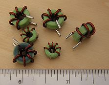
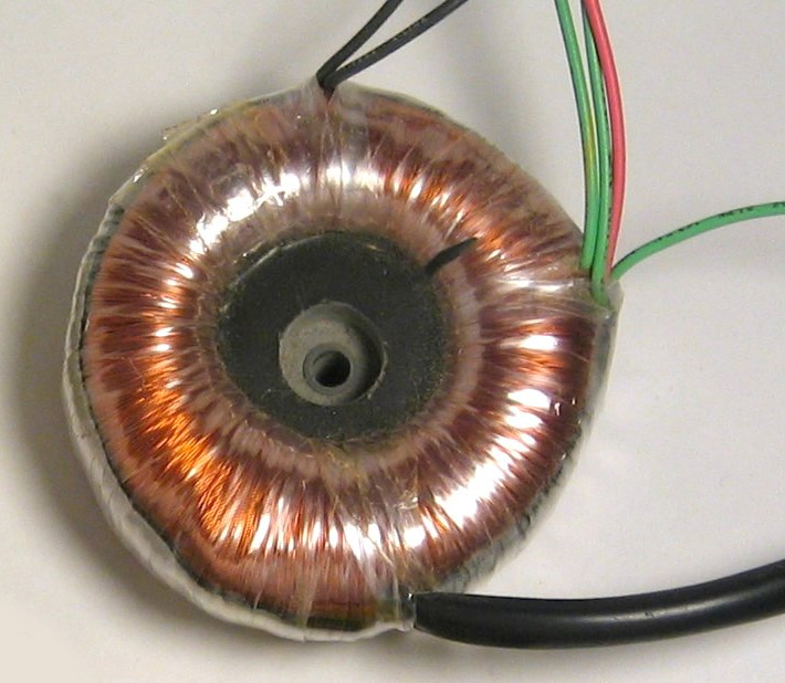
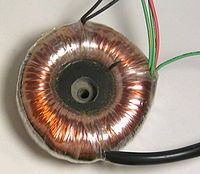 Several small toroidal inductors. The major scale is in inches.A small toroidal transformer.
Toroidal inductors and transformers are electronic components, typically consisting of a circular ring-shaped magnetic core of iron powder, ferrite, or other material around which wire is coiled to make an inductor. Toroidal coils are used in a broad range of applications, such as high-frequency coils and transformers. Toroidal inductors can have higher Q factors and higher inductance than similarly constructed solenoid coils. This is due largely to the smaller number of turns required when the core provides a closed magnetic path. The magnetic flux in a high permeability toroid is largely confined to the core; the confinement reduces the energy that can be absorbed by nearby objects, so toroidal cores offer some self-shielding.
In the geometry of torus-shaped magnetic fields, the poloidal flux direction threads the "donut hole" in the center of the torus, while the toroidal flux direction is parallel the core of the torus.
Total B Field Confinement by Toroidal Inductors
In some circumstance, the current in the winding of a toroidal inductor contributes only to the B field inside the windings and makes no contribution to the magnetic B field outside of the windings.
Sufficient conditions for total internal confinement of the B field
 Fig. 1. Coordinate system. The Z axis is the nominal axis of symmetry. The X axis chosen arbitrarily to line up with the starting point of the winding. ρ is called the radial direction. θ is called the circumferential direction.
 Fig. 2. An axially symmetric toroidal inductor with no circumferential current.
The absence of circumferential current [1] (please refer to figure 1 of this section for definition of directions) and the axially symmetric layout of the conductors and magnetic materials [1][2][3] are sufficient conditions for total internal confinement of the B field. (Some authors prefer to use the H field). Because of the symmetry, the lines of B flux must form circles of constant intensity centered on the axis of symmetry. The only lines of B flux that encircle any current are those that are inside the toroidal winding. Therefore, from Ampere's circuital law, the intensity of the B field must be zero outside the windings.[3]
 Fig. 3. Toroidal inductor with circumferential current
Figure 3 of this section shows the most common toroidal winding. It fails both requirements for total B field confinement. Looking out from the axis, sometimes the winding is on the inside of the core and sometimes it is on the outside of the core. It is not axially symmetric in the near region. However, at points a distance of several times the winding spacing, the toroid does look symmetric[4]. There is still the problem of the circumferential current. No matter how many times the winding encircles the core and no matter how thin the wire, this toroidal inductor will function as a one coil loop in the plane of the toroid. This winding will also produce and be susceptible to an E field in the plane of the inductor.
Figures 4-6 show different ways to neutralize the circumferential current. Figure 4 is the simplest and has the advantage that the return wire can be added after the inductor is bought or built.
 Fig. 4. Circumferential current countered with a return wire. The wire is white and runs between the outer rim of the inductor and the outer portion of the winding.
 Fig. 5. Circumferential current countered with a return winding.
 Fig. 6. Circumferential current countered with a split return winding.
E Field in the Plane of the Toroid
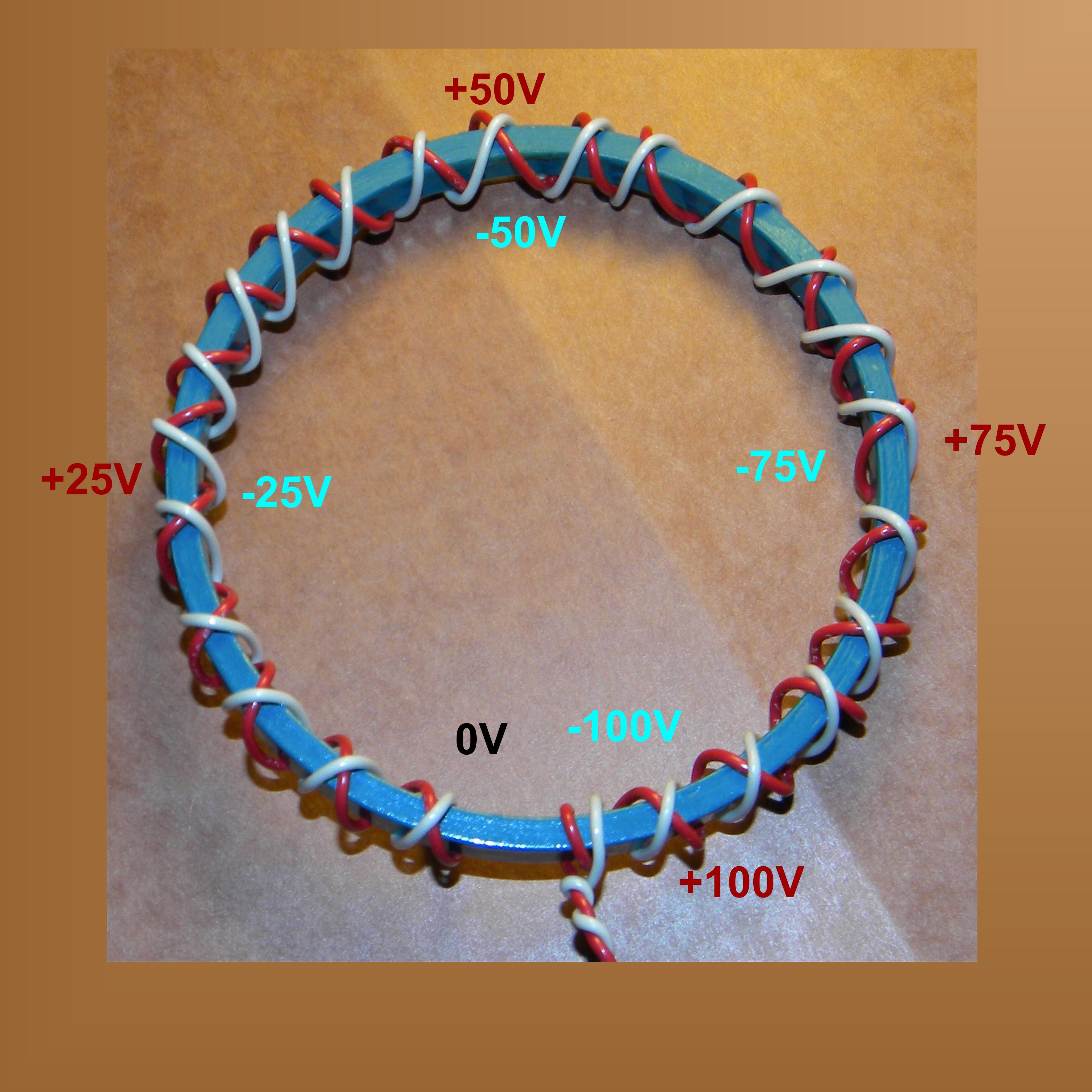
 Fig. 7. Simple toroid and the E-field produced. +/- 100 Volt excitation assumed.
 Fig. 8. Voltage distribution with return winding. +/- 100 Volt excitation assumed.
There will be a distribution of potential along the winding. This can lead to an E-Field in the plane of the toroid and also a susceptibility to an E field in the plane of the toroid as shown in figure 7. This can be mitigated by using a return winding as shown on figure 8. With this winding, each place the winding crosses itself, the two parts will be at equal and opposite polarity which substantially reduces the E field generated in the plane.
Torroidal Inductor/Transformer and Magnetic Vector Potential
Main article: Magnetic potential Showing the development of the magnetic vector potential around a symmetric torroidal inductor.
See Feynman chapter 14[5] and 15[6] for a general discussion of magnetic vector potential. See Feynman page 15-11 [7] for a diagram of the magnetic vector potential around a long thin solenoid which also exhibits total internal confinement of the B field, at least in the infinite limit.
The A field is accurate when using the assumption bfA = 0. This would be true under the following assumptions:
- 1. the Coulomb gauge is used
- 2. the Lorenz gauge is used and there is no distribution of charge,

- 3. the Lorenz gauge is used and zero frequency is assumed
- 4. the Lorenz gauge is used and a non-zero frequency that is low enough to neglect
 is assumed.
Number 4 will be presumed for the rest of this section and may be referred to the "quasi-static condition".
Although the axially symmetric toroidal inductor with no circumferential current totally confines the B field within the windings, the A field (magnetic vector potential) is not confined. Arrow #1 in the picture depicts the vector potential on the axis of symmetry. Radial current sections a and b are equal distances from the axis but pointed in opposite directions, so they will cancel. Likewise segments c and d cancel. In fact all the radial current segments cancel. The situation for axial currents is different. The axial current on the outside of the toroid is pointed down and the axial current on the inside of the toroid is pointed up. Each axial current segment on the outside of the toroid can be matched with an equal but oppositely directed segment on the inside of the toroid. The segments on the inside are closer than the segments on the outside to the axis, therefore there is a net upward component of the A field along the axis of symmetry.
 Representing the magnetic vector potential (A), magnetic flux (B), and current density (j) fields around a toroidal inductor of circular cross section. Thicker lines indicate field lines of higher average intensity. Circles in cross section of the core represent B flux coming out of the picture. Plus signs on the other cross section of the core represent B flux going into the picture. Div A = 0 has been assumed.
Since the equations
 , and
, and  (assuming quasi-static conditions, i.e.
  ) have the same form, then the lines and contours of A relate to B like the lines and contours of B relate to j. Thus, a depiction of the A field around a loop of B flux (as would be produced in a toroidal inductor) is qualitatively the same as the B field around a loop of current. The figure to the left is an artist's depiction of the A field around a totoidal inductor. The thicker lines indicate paths of higher average intensity (shorter paths have higher intensity so that the path integral is the same). The lines are just drawn to look good and impart general look of the A field.
Toroidal Transformer Action in the Presence of Total B field Confinement
The E and B fields can be computed from the A and
 (scalar electric potential) fields
 [8] and :
 [8] and so even if the region outside the windings is devoid of B field, it is filled with non-zero E field.
- The quantity
 is responsible for the desirable magnetic field coupling between primary and secondary while the quantity
  is responsible for the undesirable electric field coupling between primary and secondary. Transformer designers attempt to minimize the electric field coupling. For the rest of this section, will assumed to be zero unless otherwise specified.
Stokes theorem applies[9], so that the path integral of A is equal to the enclosed B flux, just as the path integral B is equal to a constant times the enclosed current
The path integral of E along the secondary winding gives the secondary's induced EMF (Electro-Motive Force).
which says the EMF is equal to the time rate of change of the B flux enclosed by the winding, which is the usual result.
Toroidal Transformer Poynting Vector Coupling from Primary to Secondary in the Presence of Total B field Confinement
 In this figure, blue dots indicate where B flux from the primary current comes out of the picture and plus signs indicate where it goes into the picture.
Explanation of the Figure
This figure shows the half section of a toroidal transformer. Quasi-static conditions are assumed, so the phase of each field is everywhere the same. The transformer, its windings and all things are distributed symmetrically about the axis of symmetry. The windings are such that there is no circumferential current. The requirements are met for full internal confinement of the B field due to the primary current. The core and primary winding are represented by the gray-brown torus. The primary winding is not shown, but the current in the winding at the cross section surface is shown as gold (or orange) ellipses. The B field caused by the primary current is entirely confined to the region enclosed by the primary winding (i.e. the core). Blue dots on the left hand cross section indicate that lines of B flux in the core come out of the left hand cross section. On the other cross section, blue plus signs indicate that the B flux enters there. The E field sourced from the primary currents is shown as green ellipses. The secondary winding is shown as a brown line coming directly down the axis of symmetry. In normal practice, the two ends of the secondary are connected together with a long wire that stays well away from the torus, but to maintain the absolute axial symmetry, the entire apparatus is envisioned as being inside a perfectly conductive sphere with the secondary wire "grounded" to the inside of the sphere at each end. The secondary is made of resistance wire, so there is no separate load. The E field along the secondary causes current in the secondary (yellow arrows) which causes a B field around the secondary (shown as blue ellipses). This B field fills space, including inside the transformer core, so in the end, there is continuous non-zero B field from the primary to the secondary, if the secondary is not open circuited. The cross product of the E field (sourced from primary currents) and the B field (sourced from the secondary currents) forms the Poynting vector which points from the primary toward the secondary.
Patents
- US 4127238, Potthoff, Clifford M., "Toroidal Core Winder", issued November 28, 1978
External links
- Approximate inductance of a toroid includes formula, but assumes circular windings
- toroid inductance calculator more practical, allows rectangular winding
Notes
- ^ a b Griffiths (1989, p. 222)
- ^ Reitz, Milford & Christy (1993, p. 244)
- ^ a b Halliday & Resnick (1962, p. 859)
- ^ Hayt (1989, p. 231)
- ^ Feynman (1964, p. 14_1-14_10)
- ^ Feynman (1964, p. 15_1-15_16)
- ^ Feynman (1964, p. 15_11)
- ^ a b Feynman (1964, p. 15_15)
- ^ Purcell (1963, p. 249)
References
- Griffiths, David (1989), Introduction to Electrodynamics, Prentice-Hall, ISBN 0134813677
- Halliday; Resnick (1962), Physics, part two, John Wiley & Sons
- Hayt, William (1989), Engineering Electromagnetics (5th ed.), McGraw-Hill, ISBN 0070274061
- Purcell, Edward M. (1965), Electricity and Magnetism, Berkeley Physics Course, II, McGraw-Hill, ISBN 978-0070048591
- Reitz, John R.; Milford, Frederick J.; Christy, Robert W. (1993), Foundations of Electromagnetic Theory, Addison-Wesley, ISBN 0201526247
Categories:- Transformers (electrical)


Wikimedia Foundation. 2010.